
Related Manuals for Yamaha YDX-MORO 07


Summary of Contents for Yamaha YDX-MORO 07
- Page 1 2022 ASSEMBLY MANUAL YDX-MORO 07 YDX-MORO 05 PE65M7L PE65M7M PE65M7S PE65M5L PE65M5M PE65M5S LIT-15666-00-15 X2U-28107-12...
- Page 2 This Assembly Manual contains the information required for the correct assembly of this Yamaha bicycle prior to delivery to the customer. Since some external parts of the bicycle have been removed at the Yamaha fac- tory for the convenience of packing, assembly by the Yamaha dealer is required. No adjustment of the power unit mechanism, which plays the most important part in riding, is necessary because it has been adjusted at the factory before shipping.
-
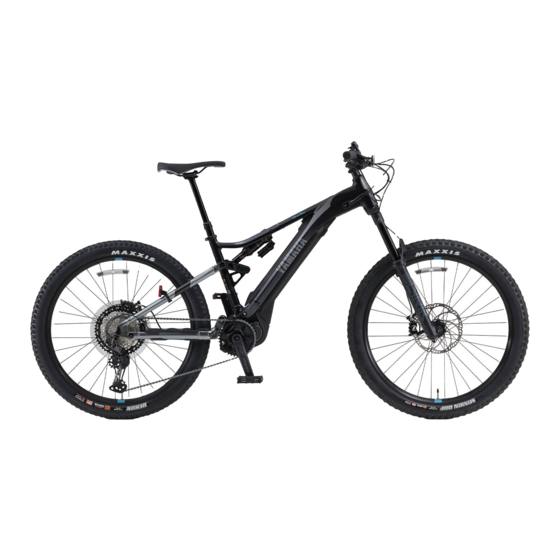
Page 3: Parts Location
PARTS LOCATION PARTS LOCATION Body assembly NOTICE 8 Do not use a cutter, scissors, or other sharp object to open the part boxes; otherwise, the included parts could be damaged. 8 Wear suitable protective gear such as gloves when handling and opening the part boxes. 1. -
Page 4: Included Parts
Part box 2 2 in part box 1 Part box 3 Part box 1 details Saddle Part box 2 details Front axle YDX-MORO 07 only Front axle YDX-MORO 05 only Pedals 1 each for left and right Bell Front reflector Rear reflector Owner’s manual... - Page 5 INCLUDED PARTS – 3 –...
- Page 6 Give the removed spacers b to the customer, explaining how it is used. (For YDX-MORO 07) Align the holes in the front wheel 1 with the holes in the fork end and install the front wheel Install it in such a way that the disc rotor c does not touch the disc pad.
- Page 7 INSTALLING THE INCLUDED PARTS Tighten the front axle 2 to the specified torque. Tightening torque 11 N·m (1.1 kgf·m, 8.1 lb·ft) WARNING Tighten the front axle 2 to the specified torque and install it securely. Otherwise, the front wheel could come off. (For YDX-MORO 05) Align the holes in the front wheel 1 with the holes in the fork end and install the front wheel...
- Page 8 INSTALLING THE INCLUDED PARTS Free the lever d. Determine the position to secure the lever d and fasten it at “CLOSE”. WARNING 8 Position the lever when it cannot touch obstacles while the bicycle is moving. If not, the lever could be unlocked unexpectedly, causing the front wheel to come off, result- ing in an accident with severe injury or death.
- Page 9 INSTALLING THE INCLUDED PARTS 3. Installing the handlebar Tightening torque 6 N·m (0.6 kgf·m, 4.4 lb·ft) Install the handlebar a so that the 3rd horizon- tal line from the top of the alignment mark b shown is positioned at the lower end of the hole in the upper handlebar holder c, and then tighten the 4 bolts d of the handlebar holder c to the specified torque.
- Page 10 INSTALLING THE INCLUDED PARTS 5. Installing the front reflector Tightening torque 1.5 N·m (0.15 kgf·m, 1.1 lb·ft) Install the front reflector 1, stay 2, and screw 3 as shown, and then tighten them together to the specified torque. Front reflector Stay Screw Install the front reflector 1 while adjusting it so that...
- Page 11 INSTALLING THE INCLUDED PARTS Secure the front brake hose 1 with the wire clamp q at the position shown in the illustra- tion. Clamp the dropper seat wire 3 and display unit lead 5 with the plastic locking ties w at the position shown in the illustration.
- Page 12 INSTALLING THE INCLUDED PARTS Check that the rear brake hose 2, shift wire 4, and speed sensor lead e are routed as shown in the illustration. 8. Installing the saddle Pinch the rail of the saddle 1 with the saddle clamps a and b, and then tighten the seat post c, bolts d, and nuts e to the specified torque.
- Page 13 INSTALLING THE INCLUDED PARTS 9. Installing the rear reflector Tightening torque 1.5 N·m (0.15 kgf·m, 1.1 lb·ft) Install the rear reflector 1, band 2, screw 3, and nut 4 as shown, and then tighten them together to the specified torque. Secure them to the frame with the band 2.
- Page 14 INSTALLING THE INCLUDED PARTS 11. Checking the operation of the speed sensor A. Press the power button a to turn on the power. B. After turning on the power, hold the power but- ton a down for approximately 10 seconds within 30 seconds.
- Page 15 INSTALLING THE INCLUDED PARTS 12. Adjusting the opening of the front and rear brake levers Before adjusting the opening of the brake levers, grip the brake levers approximately 10 times to pump them. Turn the adjusting screw 1 to adjust the open- ing of the tip of the brake lever a from the tip of the grip.
-
Page 16: Pre-Delivery Inspection
8 Check of battery pack and battery charger operation 8 Operation of the meter, switches, and drive unit 8 Installation state of the reflectors 8 Maximum tire air pressure YDX-MORO 07 (PE65M7) Front tire: 280 kPa (2.8 kgf/cm , 40.6 psi) Rear tire: 280 kPa (2.8 kgf/cm , 40.6 psi)
Need help?
Do you have a question about the YDX-MORO 07 and is the answer not in the manual?
Questions and answers