Stahl YA6S Series Operating Instructions Manual
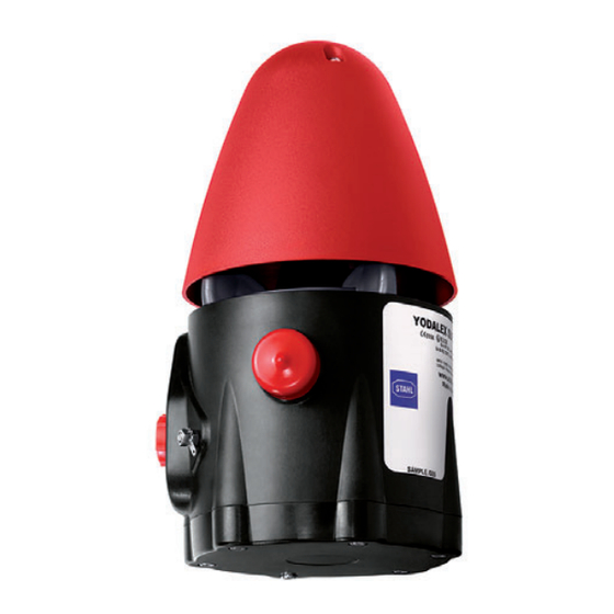
Grp audible signal – 110 db(a), flameproof
Hide thumbs
Also See for YA6S Series:
- Operating instructions manual (20 pages) ,
- Operating instructions manual (39 pages)

Subscribe to Our Youtube Channel
Related Manuals for Stahl YA6S Series


Summary of Contents for Stahl YA6S Series
- Page 1 Operating instructions Additional languages r-stahl.com GRP audible signal – 110 db(A), flameproof Series YA6S...
-
Page 2: Table Of Contents
Contents Contents General information .....................3 Manufacturer......................3 Information regarding the operating instructions..........3 Further documents....................3 Conformity with standards and regulations............3 Explanation of symbols ..................3 Symbols used in these operating instructions............3 Warning notes......................4 Symbols on the device..................5 Safety notes ......................6 Operating instructions storage ................6 Personnel qualification..................6 Safe use.......................6 Modifications and alterations ................7... -
Page 3: En Fr
They are legally binding in all legal affairs. Further documents • Data sheet For documents in other languages, see r-stahl.com. Conformity with standards and regulations IECEx, ATEX, EU Declaration of Conformity and further national certificates can be downloaded via the following link: https://r-stahl.com/en/global/support/downloads/. -
Page 4: Warning Notes
Explanation of symbols = Signal = Earth connection = Signal level 1 = Signal level 2 = Signal level 3 = Signal sound = Telephone connection = Volume controller Warning notes Warning notes must be observed under all circumstances, in order to minimise the risk resulting from design engineering and operation. -
Page 5: Se Fi
Explanation of symbols Symbols on the device Symbol Meaning CE marking according to the current applicable directive. 05594E00 Device certified for hazardous areas according to the marking. 02198E00 Input 15649E00 Output 15648E00 Safety notes that must always be observed: The corresponding data and/or safety-related instructions contained in the operating instructions must be followed for devices with this symbol! 11048E00... -
Page 6: Safety Notes
Additional knowledge is required for any activity in hazardous areas! R. STAHL recommends having a level of knowledge equal to that described in the following standards: • IEC/EN 60079-14 (Project engineering, selection and construction of electrical systems) •... -
Page 7: Modifications And Alterations
Function and device design Commissioning, maintenance, repair • Only have commissioning and repairs performed by qualified and authorised persons (see chapter "Personnel qualification"). • Before commissioning, make sure that the device is not damaged. • Perform only maintenance work described in these operating instructions. Modifications and alterations DANGER Explosion hazard due to modifications and alterations to the device! -
Page 8: 5 Technical Data
Technical data Technical data Explosion protection Global (IECEx) Gas and dust IECEx BAS 14.0064 IEC 60079-0: 2011 / IEC 60079-1: 2007 / IEC 60079-31: 2013 Ex d IIB T* Ta -** ... +** °C Gb Ex d IIC T* Ta -** ... +** °C Gb Ex tb IIIC T*** °C Ta -** ... -
Page 9: Transport And Storage
Mounting/installation Connection 2.5 mm Terminals For further technical data, see r-stahl.com. Transport and storage • Transport and store the device only in the original packaging. • Store the device in a dry place (no condensation) free of vibrations. • Do not drop the device. -
Page 10: Mounting And Installation
Mounting and installation Mounting and installation Dimensions/fastening dimensions Dimensional drawings (all dimensions in mm [inch]) – Subject to change Ø [ 0,35] Ø [1,26] [3,74] 178,50 [7,03] 189 [7,44] 16919E00 Ø [ 5,70] Ø 17150E00 GRP audible signal GRP audible signal series YA6S with L-bracket series YA6S without L-bracket ø9 [... -
Page 11: Mounting/Dismounting, Operating Position
Mounting and installation Mounting/dismounting, operating position DANGER Explosion hazard due to improper mounting! Non-compliance results in severe or fatal injuries. • Only operate the device if it is not damaged. If the thread is damaged, replace the device immediately. • Only install the device in a clean and dry operating environment. •... -
Page 12: Installation
Mounting and installation • Mount the device on a flat surface suitable for its weight. • Direct the tone output towards the area to be covered. • Insert the electrical lines using a certified and flameproof cable entry which is suitable for the gas group. - Page 13 Mounting and installation • Loosen the 6 cheese-head screws (4) and remove the end cap (3). • Prepare the cable entry. • Ensure that there is an earth connection. • Mount the cable gland. • Connect the electrical lines (see chapter 7.3.2). 17220E00 Horn End cap...
- Page 14 Mounting and installation 7.3.2 Electrical connections 17230E00 YA6S Connector for horn Terminal blocks PCB termination board Sound selection switch (see sound table) Cable connection • The connection terminal is suitable for electrical lines with a cross section of 2.5 mm or 14 to 18 AWG.
- Page 15 Mounting and installation TELEPHONE TELEPHONE INITIATE INITIATE NEUTRAL NEUTR LIVE (Vac) STROBE 24/48 Vdc STAGE AC/DC 17194E00 17193E00 Circuit diagram for direct voltages Circuit diagram for alternating voltages 224617 / YA6S60300010 GRP audible signal – 110 db(A), 2022-03-14·BA00·III·en·04 flameproof Series YA6S...
- Page 16 Mounting and installation 7.3.3 Configuration Recommendation • The signal tone selection should be set at the factory or at an approved factory. Do not use tone 12, 14 and 32 for AC variants. • For signal tone selection and its switch positions, refer to the table below. •...
- Page 17 Mounting and installation Sou- SW1/SW2 Frequency Repetition rate Sound description Special application 250 to 1200 Hz 0.085 s Fast siren 1400 Hz 0.25 s Interrupted, fast, rising volume 720 Hz 0.7/0.3 s Interrupted sound Industrial alarm, Germany 700 Hz 0.25 s Interrupted sound Local warning, Sweden 700 Hz...
- Page 18 Mounting and installation Sou- SW1/SW2 Frequency Repetition rate Sound description Special application 1000 Hz – Continuous tone 700 Hz – Continuous tone All clear, Sweden (SS 031711) 440 to 554 Hz Two alternating Turn out, tones Sweden (SS 031711) 2500 to 3200 Hz 0.07 s Two alternating tones...
- Page 19 Mounting and installation 7.3.4 Mounting the device • Lift the end cap towards the device. • Replace the M5 x 25 cheese-head screws and tighten them to a tightening torque of 4 Nm. Screws and seals The cheese-head screws are delivered with Nyltite seals. •...
-
Page 20: Commissioning
Commissioning 7.3.6 Adjusting the volume The maximum volume (depending on the selected sound) can be reduced by about 18 dB(A) using the potentiometer. 22494E00 Commissioning DANGER Explosion hazard due to incorrect installation! Non-compliance results in severe or fatal injuries. • Check the device for proper installation before commissioning. •... -
Page 21: Operation
If an error occurs please re-visit the earlier sections of this document. If the error cannot be eliminated using the specified procedures: • Contact R. STAHL Schaltgeräte GmbH. For rapid processing, have the following information ready: • Type and serial number of the device •... -
Page 22: 10.3 Returning The Device
• Only return or package the devices after consulting R. STAHL! Contact the responsible representative from R. STAHL. R. STAHL's customer service is available to handle returns if repair or service is required. • Contact customer service personally. • Go to the r-stahl.com website.
Need help?
Do you have a question about the YA6S Series and is the answer not in the manual?
Questions and answers