Extron electronics FOX3 Matrix Series Setup Manual
Hide thumbs
Also See for FOX3 Matrix Series:
- User manual (81 pages) ,
- Installation manual (4 pages) ,
- Setup manual (13 pages)
Table of Contents
Advertisement
Quick Links
FOX3 Matrix Series • Setup Guide
General Setup
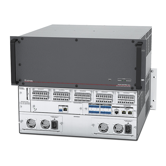
The FOX3 Matrix Switchers are configurable matrix switchers that distribute optical and audio signals. The FOX3 Matrix is
primarily designed to support switching of FOX3 endpoints, FOX3 transmitters to FOX3 receivers. The matrix switcher routes any
input signal to any combination of outputs. The FOX3 Matrix switcher can also route multiple input and output configurations
simultaneously (see figure 1 for a FOX3 Matrix 80x configuration).
WARNING:
The FOX3 Matrix switcher fiber optic I/O boards output continuous invisible light, which may be harmful to
the eyes; use with caution. Do not look into the fiber optic cable connectors or into the fiber optic cables themselves. Plug
the attached dust caps into the optical transceivers when the fiber cable is unplugged.
AVERTISSEMENT :
être dangereuse pour les yeux ; à utiliser avec précaution. Ne pas fixer directement les connecteurs optiques ou les câbles
fibre optique. Branchez les protections contre la poussière dans l'ensemble émetteur/récepteur lorsque le câble fibre
optique est débranché.
NOTE:
FOX3 Matrix is not compatible with FOX and FOX II signals unless a matrix partition is created and configured to
support 4G signals in PCS (see the FOX3 Matrix Series PCS Help File for details on partitioning). In the event of a factory
reset, the data rate resets to the factory default of 10G.
Computer
Computer
Computer
Computer
IPCP Pro 555
IP Link Pro Control
Processor
100-240V ~ 50-60Hz
1
2
1
2
Tx Rx G Tx R x G Tx Rx G Tx Rx G RTS
SWITCHED 12 VDC
40W MAX TOTAL
3
4
4
5
Tx R x G Tx Rx G Tx R x G Tx R x G RTSCTS
1.2A MAX
12 VDC
Figure 1.
Les cartes d'E/S fibre optique FOX3 Matrix switcher émettent une lumière invisible continue, qui peut
FOX3 T 301
Fiber Optic Transmitter
for HDMI
100-240V
0.7A MAX
INPUTS
FOX3 T 301
L
R
RS-232
IR
HDMI
Tx
Rx
G
Tx Rx
OUTPUTS
A
B
USB HID
USB 2.0
REMOTE
3D
LAN
AUDIO
SYNC
L
R
RS-232
LOOP OUT
R
HOST
HOST
Tx Rx G S 5V
OUT
IN
OUT IN
50-60 Hz
USB
4K HDMI
FOX3 T 301
Fiber Optic Transmitter
for HDMI
100-240V
0.7A MAX
L
R
INPUTS
RS-232
IR
FOX3 T 301
HDMI
Tx
Rx
G
Tx Rx
OUTPUTS
A
B
REMOTE
3D
USB HID
USB 2.0
LAN
AUDIO
SYNC
L
R
LOOP OUT
RS-232
R
HOST
HOST
Tx Rx G S 5V
OUT
IN
OUT IN
50-60 Hz
USB
4K HDMI
FOX3 T 301
Fiber Optic Transmitter
for HDMI
100-240V
0.7A MAX
L
R
INPUTS
RS-232
IR
FOX3 T 301
HDMI
Tx
Rx
G
Tx Rx
OUTPUTS
REMOTE
3D
A
B
USB HID
USB 2.0
LAN
AUDIO
SYNC
L
R
LOOP OUT
RS-232
R
HOST
HOST
Tx Rx G S 5V
OUT
IN
OUT IN
50-60 Hz
USB
4K HDMI
FOX3 T 301
Fiber Optic Transmitter
for HDMI
100-240V
0.7A MAX
INPUTS
FOX3 T 301
L
R
RS-232
IR
HDMI
Tx
Rx
G
Tx Rx
OUTPUTS
A
B
USB HID
USB 2.0
REMOTE
3D
LAN
AUDIO
SYNC
L
R
LOOP OUT
RS-232
R
HOST
HOST
Tx Rx G S 5V
OUT
IN
OUT IN
50-60 Hz
USB
4K HDMI
FOX3 MATRIX 8io
OUT
1
IN
OUT
2
IN
5
OUT
IN
6
OUT
FOX3 MATRIX 8io
1
2
OUT
IN
OUT
5
6
IN
OUT
IN
OUT
RESET
Ethernet
3
7
1
2
3
4
1
2
3
4
PWR OUT = 12W
LAN
S G S G
S G S G
+V +S -S G
eBUS
6
8
5
6
7
8
5
6
7
8
1
2
3
4 G
AV
LAN
S G S G
S G S G
Ethernet
COM
IR/SERIAL
RELAYS
FLEX I/O
Typical FOX3 Matrix Application
USB
USB
USB
4K HDMI
RS-232
100-240V
0.7A MAX
L
R
OUTPUTS
RS-232
IR
FOX3 R 301
DEVICES
INPUTS
Tx
Rx
G
Tx Rx
USB HID
HDMI
A
B
1
REMOTE
3D
LAN
AUDIO
SYNC
L
R
USB 2.0
RS-232
2
1
100mA
500mA
50-60 Hz
Tx Rx G S 5V
OUT
IN
OUT IN
FOX3 R 301
Fiber Optic Receiver
for HDMI
USB
USB
USB
4K HDMI
RS-232
100-240V
0.7A MAX
L
R
OUTPUTS
FOX3 R 301
RS-232
IR
DEVICES
Tx
Rx
G
Tx Rx
INPUTS
USB HID
HDMI
A
B
1
REMOTE
3D
LAN
AUDIO
SYNC
L
R
USB 2.0
RS-232
2
1
100mA
500mA
50-60 Hz
Tx Rx G S 5V
OUT
IN
OUT IN
FOX3 R 301
Fiber Optic Receiver
for HDMI
FOX3 Matrix 80x
FOX3 MATRIX 8io
FOX3 MATRIX 8io
FOX3 MATRIX 8io
FOX3 MATRIX 8io
IN
OUT
3
IN
OUT
4
IN
OUT
1
IN
OUT
2
IN
OUT
3
IN
OUT
4
IN
OUT
1
IN
OUT
2
IN
OUT
3
IN
OUT
4
IN
OUT
1
IN
OUT
2
IN
OUT
3
IN
OUT
4
IN
OUT
1
IN
OUT
2
IN
OUT
3
IN
OUT
4
IN
Modular Fiber Optic
IN
7
OUT
IN
8
OUT
IN
5
OUT
IN
6
OUT
IN
7
OUT
IN
8
OUT
IN
5
OUT
IN
6
OUT
IN
7
OUT
IN
8
OUT
IN
5
OUT
IN
6
OUT
IN
7
OUT
IN
8
OUT
IN
5
OUT
IN
6
OUT
IN
7
OUT
IN
8
OUT
FOX3 MATRIX 8io
FOX3 MATRIX 8io
FOX3 MATRIX 8io
FOX3 MATRIX 8io
3
4
1
2
3
4
1
2
3
4
1
2
3
4
1
2
3
4
Matrix Switcher
IN
OUT
IN
OUT
IN
OUT
IN
OUT
IN
OUT
IN
OUT
IN
OUT
IN
OUT
IN
OUT
IN
OUT
IN
OUT
IN
OUT
IN
OUT
IN
OUT
IN
OUT
IN
OUT
IN
OUT
IN
OUT
IN
7
8
5
6
7
8
5
6
7
8
5
6
7
8
5
6
7
8
IN
OUT
IN
OUT
IN
OUT
IN
OUT
IN
OUT
IN
OUT
IN
OUT
IN
OUT
IN
OUT
IN
OUT
IN
OUT
IN
OUT
IN
OUT
IN
OUT
IN
OUT
IN
OUT
IN
OUT
IN
OUT
FOX3 MATRIX
AUDIO OUTPUTS
FOX3 MATRIX AUDIO
CONTROL FL
AUDIO INPUTSS
DANTE EXPANSION
L
R
L
R
L
R
L
R
AUDIO EXPANSION
REMOTE
LAN
DMP
1
3
1
3
EXPANSION
AT
2
4
2
4
RS-232
L
R
L
R
L
R
L
R
Tx Rx G
FOX3 MATRIX 80x
DISCONNECT POWER
DISCONNECT POWER
CORD BEFORE
CORD BEFORE
SERVING
SERVING
PRIMARY
REDUNDANT
~
~
100-240V
x.xA MAX.
100-240V
x.xA MAX.
50/60Hz
50/60Hz
TLP Pro 725M
7" Wall Mount TouchLink
Pro Touchpanel
AV Control
Ethernet
Network
Keyboard
Mouse
USB Headset
MODEL 80
FLAT PANEL
4K Display
R
Keyboard
Mouse
USB Headset
MODEL 80
FLAT PANEL
4K Display
R
1
Advertisement
Table of Contents

Related Manuals for Extron electronics FOX3 Matrix Series


Summary of Contents for Extron electronics FOX3 Matrix Series
- Page 1 FOX3 Matrix is not compatible with FOX and FOX II signals unless a matrix partition is created and configured to support 4G signals in PCS (see the FOX3 Matrix Series PCS Help File for details on partitioning). In the event of a factory reset, the data rate resets to the factory default of 10G.
-
Page 2: Rear Panel
FOX3 Matrix Series • Setup Guide (Continued) The Extron proprietary fiber optic signal, generated by Extron fiber optic transmitters, can include video, stereo audio, USB 2.0, USB HID, return audio, IR, and 3D sync. The matrix switcher can be remotely controlled via the rear panel Ethernet LAN port, rear panel RS-232 port (SIS only), or front... -
Page 3: Rear Panel Overview
Reset button and LED — Initiate three levels of reset of the matrix switcher. For different reset levels, press and hold the recessed button while the switcher is running or while powering up the switcher (see the FOX3 Matrix Series User Guide, available at www.extron.com... - Page 4 FOX3 Matrix Series • Setup Guide (Continued) FOX3 Matrix 24x, 40x, 80x, 160x — • 100-240 VAC, 50-60 Hz power source. • Connect via standard IEC power cord. FOX3 Matrix 320x only — North America — • Nominal 120 VAC, 60 Hz, 20 A protected power source.
- Page 5 Reset button and LED — Initiate three levels of reset of the matrix switcher. For different reset levels, press and hold the recessed button while the switcher is running or while powering up the switcher (see the FOX3 Matrix Series User Guide, www.extron.com...
-
Page 6: Front Panel
USB group switching for cross display applications (see the FOX3 Matrix System Map Setup Guide available at www.extron.com and FOX3 Matrix Series PCS Help File in PCS for detailed instructions). Remote Control This section describes using the remote control features of the FOX3 Matrix switchers to control the devices. -
Page 7: Command And Response Table For Sis Commands
Command and Response Table for SIS Commands Command ASCII Command Response Additional Description (Host to Unit) (Unit to Host) 1*1!002*002!003*003! NOTE: Commands can be entered back-to-back in a string, with no spaces. For example: Output switching NOTES: • The quick multiple tie and tie input to all output commands activate all I/O switches simultaneously. 001*001 50001*50001 •... - Page 8 FOX3 Matrix Series • Setup Guide (Continued) Command ASCII Command Response Additional Description (Host to Unit) (Unit to Host) Quick tie NOTES: • The quick multiple tie and tie input to all outputs commands activate all I/O switches simultaneously. 001*001 50001*50001 •...
-
Page 9: Installing The Program
Command ASCII Command Response Additional Description (Host to Unit) (Unit to Host) Verbose Mode E X2) X2) ] Set verbose mode X2) ] View verbose mode NOTE: Verbose mode will revert back to default in the event of a power cycle, disconnect from dataviewer, or disconnect from the Ethernet. KEY: = Verbose mode = Clear/none (default for Ethernet),... - Page 10 FOX3 Matrix Series • Setup Guide (Continued) Figure 10. Device Discovery Panel If connecting through the front panel USB-C port or the rear panel AV LAN port, select the FOX3 Matrix device by ) and click Connect ( clicking on it to highlight it in the list ( If connecting through the rear panel IPCP LAN port: •...
-
Page 11: Disabling Compatibility Mode
If connecting through the rear panel IPCP LAN port, enter the FOX3 Matrix IP Address/Hostname and Password in the Target Device panel (see figure 11, on page 10). Select the Enable Indirect Connection checkbox ( ). The IP Link Pro Control Processor with AV LAN panel ( is enabled. -
Page 12: Accessing The Internal Web Page
FOX3 Matrix Series • Setup Guide (Continued) Accessing the Internal Web Page Access the FOX3 Matrix internal web page as follows: Connect the FOX3 Matrix to a LAN or WAN using the rear panel RJ-45 LAN port on the standard FOX3 Matrix (see figure 2, ) or the front panel USB config port (see figure 7,... -
Page 13: Maintenance And Modifications
Figure 15. Internal Web Main Page NOTE: For detailed information about the internal web page, see the FOX3 Matrix Series User Guide available at www.extron.com. Maintenance and Modifications This section describes repairing and reconfiguring the FOX3 Matrix switchers by replacing components. - Page 14 FOX3 Matrix Series • Setup Guide (Continued) ATTENTION: • Do not touch the electronic components or the connectors on the backplane or on the circuit boards without being electrically grounded. Handle circuit boards by their edges only. Electrostatic discharge (ESD) can damage circuits, even though you cannot feel, see, or hear it.
-
Page 15: Replacing A Power Supply Module
Replacing a Power Supply Module The two power supply modules (primary power supply and redundant power supply) are identical. Each power supply module has a 2-color LED, visible on the front panel, that indicates the status of the power supply outputs. If the LED is lit green, the power supply is operating normally. - Page 16 For information on safety guidelines, regulatory compliances, EMI/EMF compatibility, accessibility, and related topics, see the Extron Safety and Regulatory Compliance Guide on the Extron website. 68-2987-50 Rev. E © 2020-2022 Extron — All rights reserved. www.extron.com 09 22 All trademarks mentioned are the property of their respective owners. Worldwide Headquarters: Extron USA West, 1025 E.
Need help?
Do you have a question about the FOX3 Matrix Series and is the answer not in the manual?
Questions and answers