Table of Contents
Advertisement
Quick Links
Advertisement
Table of Contents

Related Manuals for Galletti IWCi


Summary of Contents for Galletti IWCi
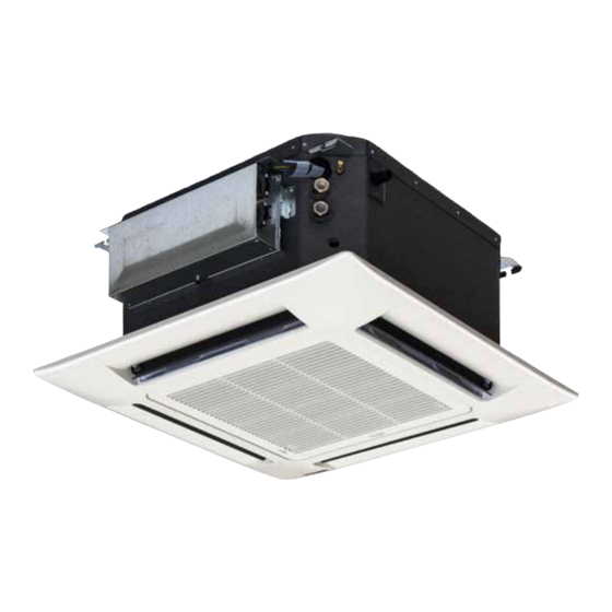
- Page 1 TECHNICAL MANUAL IWCi CASSETTE FAN COILS WITH INVERTER (2,6 kW - 9,9 kW)
-
Page 2: Table Of Contents
CONTENTS PRODUCT CHARACTERISTICS 1. PRODUCT CHARACTERISTICS ..............2 With a solid thirty-years of experience in fan coil production, Galletti presents the new IWCi brushless line. 2. CONSTRUCTION CHARACTERISTICS ............3 Galletti cassettes are equipped with a latest generation permanent magnet (brushless) 3. -
Page 3: Construction Characteristics
HUMIDITY SENSORS AND PERCEIVED TEMPERATURE MANAGEMENT One of a kind on the market, IWCi incorporates a relative humidity sensor inside its particularly evolved electronics. The humidity sensor signal is used by the logic by placing it in relation with the temperature measured by the room air and Humidex sensor, which measures the perception of the human body considering the combined effects 1°C... - Page 4 • Limit speed 0.2 m/s. This panel differs from the version equipped for wired controller, where fin MODEL IWCi 32-34 IWCi 42-44 IWCi 52 IWCi 62 IWCi 82 IWCi 102...
-
Page 5: Nominal Technical Characteristics
NOMINAL TECHNICAL CHARACTERISTICS NOMINAL TECHNICAL CHARACTERISTICS FOR IWCi FAN COILS, MODELS WITH 1 COIL MODEL Speed Total cooling output (1) 1,24 2,15 2,35 2,60 1,70 3,50 4,00 4,60 2,47 3,80 4,42 5,06 Sensitive cooling output (1) 0,91 1,78 2,00 2,23... - Page 6 IWCi NOMINAL TECHNICAL CHARACTERISTICS FOR IWCi FAN COILS, MODELS WITH 2 COILS MODEL Speed Total cooling output (1) 1,10 1,72 1,88 2,05 1,58 2,88 3,28 3,76 Sensitive cooling output (1) 0,83 1,51 1,66 1,82 1,10 2,27 2,60 3,00 Water flow rate (1)
-
Page 7: Performances
PERFORMANCES In order to define the performances of IWCi subject to conditions different from rated conditions, a computer program for the correct choice of the units is provided by Galletti SpA. With a few input data it will be possible to get information on the behaviour of an IWCi referring to the desired operating conditions. -
Page 8: Sound Levels
4, med 3, min 2, smin 1 Unweighted sound power level for octave band Global A-weighted sound pressure level, calculated at a distance of 1m with direction factor of 4 OVERALL FOOTPRINT IWCi 3-4-5-6-8-10, 2 PIPES IWCi 3-4, 4 PIPES NET WEIGHT NET WEIGHT Model... - Page 9 OVERALL FOOTPRINT IWCi 032 - 042 - 052 - 034 - 044 LEGEND Condensate hole: Ø 18 mm Main heat exchanger water inlet: ½” gas female Main heat exchanger water outlet: ½” gas female Additional heat exchanger water inlet: ½” gas female* Additional heat exchanger water outlet: ½”...
- Page 10 IWCi IWCi 062 LEGEND Condensate hole: Ø 32 mm Water inlet: 3/4” gas female Water outlet: 3/4” gas female Heat exchanger air vent Electrical cable passage Fresh air intake: 60x55 mm It is strictly forbidden to reproduce this manual, even partially...
- Page 11 IWCi 082 - 102 1050 1050 1150 1150 LEGEND Condensate hole: Ø 32 mm Water inlet: 3/4” gas female Water outlet: 3/4” gas female Heat exchanger air vent Electrical cable passage Fresh air intake: 60x55 mm WC66000122 - Rev 03...
-
Page 12: Connections
IWCi CONNECTIONS IWCi 3-4-5 WATER CONNECTIONS • 1/2” female (MODELS IWCi 3-4-5) 3/4" (MODELS IWCi 6-8-10) gas connection on the unit: - Water inlet: bottom connection. - Water outlet: top connection. • For use during cooling, is it essential to have a motorised valve installed,... - Page 13 FRESH AIR CONNECTION (IWCi 3-4-5) • avoid operating noise-related problems, air flow rate must be approximately 10% of the total air flow rate. • The unit can be connected to an external air duct (17). Open provided hole (18), secure Ø...
- Page 14 IWCi ELECTRICAL CONNECTIONS IWCi 3-4-5 General Information • Class 1 equipment. • The electrical installation must be set up in accordance with standards and regulations in force (specifically standards NF C 15-100 IEC 364). Connection specifications • A few cable clamps are set up to keep the cables at their inlet on the panel.
- Page 15 SACBUS CONNECTION MASTER UNIT / SLAVE UNIT SETTING Set micro-switch 1 of SW2 on OFF for the MASTER UNIT, and on ON for the SLAVE UNITS. NOTES • Max. length (total cable sum): 250m Min. length between units: 0.5m • Only one unit can be set as the MASTER.
- Page 16 IWCi MODBUS CONNECTION UNIT Make sure that micro-switch 1 of SW2 is on OFF (factory setting). SETTING ADDRESSES THROUGH REMOTE CONTROLLER 1 - 3 1. Hold the CLEAN key down for 7 seconds. 2. Press the + and - keys until you get the number you require for the address (01, 02, 03...99).
- Page 17 MIXED MODBUS / SACBUS CONNECTION NOTES • Units set as SLAVES cannot be connected to the MODBUS. • MODBUS control can only be set up on MASTER units. • If MODBUS control is running, the signals from the remote controls of the units will be ignored.
-
Page 18: Modbus Protocol
IWCi MODBUS PROTOCOL MODBUS _Holding_LimitMaxRiscaldamento_ ............5 The protocol implemented in the cassette is Modbus RTU (19200,N,8,1) _Holding_VelocitaVentilazione_ ............6 on RS485. _Holding_WorkMode_ ................7 _Holding_PosizioneFlap_ ..............8 IMPLEMENTED FUNCTIONS _Holding_DryTreshold_ ..............9 READ_COILS 0x1 _Holding_UsaModbus_ ..............20 READ_DISCRETE_INPUTS 0x2 _Holding_EconomyMode_ ...............21 READ_HOLDING_REGISTERS 0x3 _Holding_TurboMode_ ..............22 READ_INPUT_REGISTERS 0x4 _Holding_SdoppiamentoVelocita_ ............23... -
Page 19: Electrical Diagrams
WIRING DIAGRAMS IWCi 3-4-5 WIRE COLOURS SYMBOLS OF PARTS White Condensation Pump Black FLAP1,2 Deflector motor Grey Internal fan motor Electronic board Yellow TH1,2 Termistor Brown Power relay Violet Level sensor Orange Pink Blue GRN/YEL Yellow/Green WC66000122 - Rev 03... - Page 20 Win) Control regulating logics will keep water probes, air probes and condensate discharge pump under control. This function allows to manage the cassette through Galletti EVO and MyComfort Large controls. Please follow the diagram for a correct wiring. Data cables must not be close to electromagnetic interference sources.
- Page 21 1 - JUMPERS SETTING C = Closed O = Open 2 - FUNCTIONS: A = Available E = Not available (When it selected from the remote controller, all of the lights will flash) Any configuration other than the factory setting must be carried out by qualified staff.
- Page 22 IWCi REMOTE CONTROLLER: ADDRESS SELECTOR Before opening the unit, make sure that the unit is switched off and that the main current switch is on OFF. ELECTRONIC BOARD - PCB If several units are installed (up to 4) in the same room, it will be necessary to aim each remote controller towards its own inside unit.
-
Page 23: Units And Accessories
UNITS AND ACCESSORIES 3-WAY AND 4X2 MOTORISED VALVE KIT ON/OFF MOTORISED 2-WAY VALVE KIT The 3-way valve is used to direct the water flow into the coil inside the unit or into The ON/OFF motorised 2-way valve KVK kit is designed to stop the water flow the cooling unit return branch. - Page 24 IWCi 3-WAY VALVE KIT - 4 FITTINGS - 1-COIL UNIT 3-WAY VALVE KIT - 4 FITTINGS - 2-COIL UNIT It is strictly forbidden to reproduce this manual, even partially WC66000122 - Rev 03...
- Page 25 4X2 VALVE KIT SUMMER MODE 3-4-5 COLD CIRCUIT VALVE HOT CIRCUIT VALVE WATER OUTLET WATER INLET In order to avoid leakage, the maximum pressure difference between the hot side and the cold side of the plumbing circuit must be less than 1 bar. 4X2 VALVE KIT WINTER MODE 3-4-5 COLD CIRCUIT VALVE HOT CIRCUIT VALVE...
- Page 26 IWCi 4X2 VALVE KIT SUMMER MODE 6-8-10 COLD CIRCUIT VALVE WATER OUTLET WATER INLET HOT CIRCUIT VALVE In order to avoid leakage, the maximum pressure difference between the hot side and the cold side of the plumbing circuit must be less than 1 bar.
- Page 27 2-WAY VALVE - 1-COIL UNIT KIT 3-4-5 WATER OUTLET WATER INLET 2-WAY VALVE - 2-COIL UNIT KIT 3-4 ADDITIONAL COIL WATER OUTLET MAIN COIL WATER OUTLET MAIN COIL WATER INLET ADDITIONAL COIL WATER INLET WC66000122 - Rev 03 It is strictly forbidden to reproduce this manual, even partially...
- Page 28 IWCi 2-WAY VALVE - 1-COIL UNIT KIT 6-8-10 Water outlet Water inlet It is strictly forbidden to reproduce this manual, even partially WC66000122 - Rev 03...
- Page 29 CASSETTE FAN COILS, 1 COIL Code Description SAIWC032TI0 1-coil IWCi 032 unit SAGWC030TI0 IWCi grill 032 - 052 SAIWC042TI0 1-coil IWCi 042 unit SAGWC030TI0 IWCi grill 032 - 052 SAIWC052TI0 1-coil IWCi 052 unit SAGWC030TI0 IWCi grill 032 - 052...
- Page 30 IWCi ACCESSORIES Code Description SATWC000TI0 Infra-red remote control device for remote controller or wired connection IWCIF000FI0 Wire kit EYMCLE MYCOMFROT LARGE - LCD controller for BLDC indoor units EYEVOBOARD EVO I/O board 230V EYEVODISP Remote display EVO CLOCK COMPULSORY ACCESSORIES Valve kit that cuts off the fluid based on adjustment thermostat control, which can be either 2-way valve, 3-way valve/fittings and 4x2 kit, with ON/OFF or modulating motors.
- Page 31 WC66000122 - Rev 03 It is strictly forbidden to reproduce this manual, even partially...
- Page 32 40010 Bentivoglio (BO) Via Romagnoli 12/a Tel. 051/8908111 - Fax. 051/8908122 Certified UNI EN ISO 9001 and OHSAS 18001 company...
Need help?
Do you have a question about the IWCi and is the answer not in the manual?
Questions and answers