Table of Contents
Advertisement
Advertisement
Table of Contents

Related Manuals for Galletti IWC32


Summary of Contents for Galletti IWC32
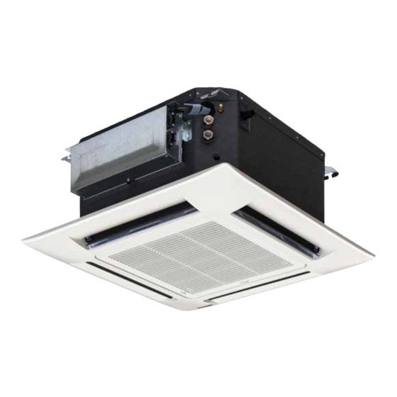
- Page 1 TECHNICAL MANUAL CASSETTE FAN COILS 2,6 kW - 9,1 kW...
-
Page 2: Table Of Contents
TABLE OF CONTENTS CONSTRUCTION VERSIONS: Constructive features .............2 • Cassette fan coils (2 pipe systems), cable control (optional). Construction versions ............2 • Cassette fan coils (4 pipe systems), cable control (optional). Air range ................3 OPERATING LIMITS Ratings and technical data .............4 •... -
Page 3: Air Range
AIR RANGE • Fin inclination 45° • Limit speed 0.2 m/s MODE • Heating in nominal conditions Model IWC32-34 IWC42-44 IWC52 IWC62 IWC82 Speed Air range Height Distance WC66000113 - Rev 04 All copying, even partial, of this manual is strictly forbidden. -
Page 4: Ratings And Technical Data
4 = sound power conforming to ISO 3741 and ISO 3742 5 = Sound pressure level measured at a distance of 1 m with a directivity factor of 4 Galletti SpA takes part in the EUROVENT Certification Programme. The products involved can be seen at www.eurovent-certification.com All copying, even partial, of this manual is strictly forbidden. - Page 5 4 = sound power conforming to ISO 3741 and ISO 3742 5 = Sound pressure level measured at a distance of 1 m with a directivity factor of 4 Galletti SpA takes part in the EUROVENT Certification Programme. The products involved can be seen at www.eurovent-certification.com WC66000113 - Rev 04 All copying, even partial, of this manual is strictly forbidden.
-
Page 6: Performance
In order to define the performances of IWC subject to conditions different from rated conditions, a computer program for the correct choice of the units is provided by Galletti SpA. With a few input data it will be possible to get information on the behaviour of an IWC referring to the desired operating conditions. -
Page 7: Sound Levels
SOUND LEVELS Fan speed smin Sound power level by octave band, not weighted Total sound power level, weighted A Total sound pressure level, weighted A, measured at a distance of 10 m, with a directivity factor of 2. 125 Hz 250 Hz 500 Hz 1000 Hz... -
Page 8: Overall Dimensions
OVERALL DIMENSIONS IWC 03-04-05, 2 PIPES Suspension brackets Suspension brackets Ceiling Suspension brackets Net weight Model IWC 3 IWC 4-5 Unit 18 kg 20 kg Fresh air intake side Panel/grille assembly 2.5 kg 2.5 kg Suspending rod Ceiling Electric control board Nuts and washers Water connection side Foro condensa: Ø... - Page 9 OVERALL DIMENSIONS IWC 06-08, 2 PIPES Net weight Model IWC 6 IWC 8 Unit 23 kg 29 kg Panel/grille assembly 5 kg 7 kg Condensate hole: 32 mm Ø OD Water inlet: ¾” gas female Model Water outlet: ¾” gas female Coil air vent IWC 6 Electrical cable passage...
- Page 10 ELECTRICAL CONNECTIONS GENERALITIES • Class 1 Unit. • The electrical installation must comply with current standards and regulations (paying particular attention to standards NF C 15-100, CEI 364). DETAILS OF CONNECTIONS • Several cable clamps are provided to secure the cables at the entry to the control panel. •...
-
Page 11: Wiring Diagrams
ELECTRICAL CONNECTIONS MODELS WITH CABLE CONTROL For the connection to the power supply, use the terminal X1 (terminals U, N and PE) of the printed circuit board situated on the electric control board (see drawing alongside). WIRING DIAGRAMS: MODELS WITH REMOTE CONTROL Component symbols Wire colours White... - Page 12 ELECTRICAL CONNECTIONS IWC 3-4 IWC 5 All copying, even partial, of this manual is strictly forbidden. WC66000113 - Rev 04...
- Page 13 ELECTRICAL CONNECTIONS IWC 6-8 WC66000113 - Rev 04 All copying, even partial, of this manual is strictly forbidden.
- Page 14 ELECTRICAL CONNECTIONS 1 - JUMPER setting C = Closed O = Open 2 - Functions: A = Available E = Not available (When selected from the remote control, all signals are flashing) Note: Configurations other than factory configurations must be carried out by qualified personnel.
- Page 15 ELECTRICAL CONNECTIONS IWC 3-4 WITH CABLE CONTROL IWC 3-4 WITH CABLE CONTROL (2 PIPES) WC66000113 - Rev 04 All copying, even partial, of this manual is strictly forbidden.
- Page 16 ELECTRICAL CONNECTIONS IWC 5 WITH CABLE CONTROL IWC 6-8 WITH CABLE CONTROL All copying, even partial, of this manual is strictly forbidden. WC66000113 - Rev 04...
- Page 17 ELECTRICAL CONNECTIONS IWC + MYCOMFORT BASE + KP WC66000113 - Rev 04 All copying, even partial, of this manual is strictly forbidden.
- Page 18 ELECTRICAL CONNECTIONS IWC + MYCOMFORT MEDIUM + KP All copying, even partial, of this manual is strictly forbidden. WC66000113 - Rev 04...
- Page 19 ELECTRICAL CONNECTIONS IWC + MYCOMFORT LARGE + KP WC66000113 - Rev 04 All copying, even partial, of this manual is strictly forbidden.
- Page 20 ELECTRICAL CONNECTIONS IWC + LED503 + KP All copying, even partial, of this manual is strictly forbidden. WC66000113 - Rev 04...
-
Page 21: Accessories
CONTROLLER Using the installation kit available, MYCOMFORT can be mounted on the unit The control software developed by the Galletti Software Dept., features: MYCOMFORT LARGE - wall-mounted microprocessor control, GALLETTI model - manual selection of fan speed;... - Page 22 ACCESSORIES 3-way motor driven valve and 4x2 motor driven valve kit The kit includes: Brass 3-way valve / 4 connections with built-in by-pass, maximum operating pressure 16 bar; Electrothermal ON/OFF actuator featuring: power supply: 230 V ON/OFF function (or modulating) total opening time: 4 minutes Water out Water out...
-
Page 23: All Copying, Even Partial, Of This Manual Is Strictly Forbidden
IWC 03-04-05 4X2 VALVE WINTER MODE OPERATION COLD CIRCUIT VALVE HOT CIRCUIT VALVE WARNING: In order to avoid leakage WATER OUTLET problems, the maximum pressure difference between WATER INLET the hot side and the cold side of the water circuit should be lower than 1 bar. - Page 24 IWC 03-04 4 TUBI, IWC 03-04 4 PIPES Valvola a 2 vie - 2-Way valve Additional heat exchanger water outlet Main heat exchanger water outlet Additional heat Main heat exchanger exchanger water inlet water inlet IWC 03-04-05 2 TUBI, IWC 03-04-05 2 PIPES Valvola a 2 vie - 2-Way valve Water outlet Water inlet...
- Page 25 IWC 06-08 2 TUBI, IWC 06-08 2 PIPES Valvola a 2 vie - 2-Way valve Water outlet Water inlet WC66000113 - Rev 04 All copying, even partial, of this manual is strictly forbidden.
- Page 26 Valve Kit Code Unit Version Valve Type Actuator Water connections IWYVK2V04410 IWC03-04 4 pipes 2-way 230 V - ON/OFF 1/2" Gas-F IWYVK2V04420* IWC03-04 4 pipes 2-way Modulating 0-10V 1/2" Gas-F IWYVK2V04430 IWC03-04 4 pipes 2-way 24V - ON/OFF 1/2" Gas-F IWYVK2V05210 IWC03-04-05 2 pipes...
- Page 27 NOTES...
- Page 28 40010 Bentivoglio (BO) Via Romagnoli 12/a Tel. 051/8908111 - Fax. 051/8908122 Company UNI EN ISO 9001 and OHSAS 18001 certified...
Need help?
Do you have a question about the IWC32 and is the answer not in the manual?
Questions and answers