Table of Contents
Advertisement
Advertisement
Table of Contents

Related Manuals for Galletti UTN Series


Summary of Contents for Galletti UTN Series
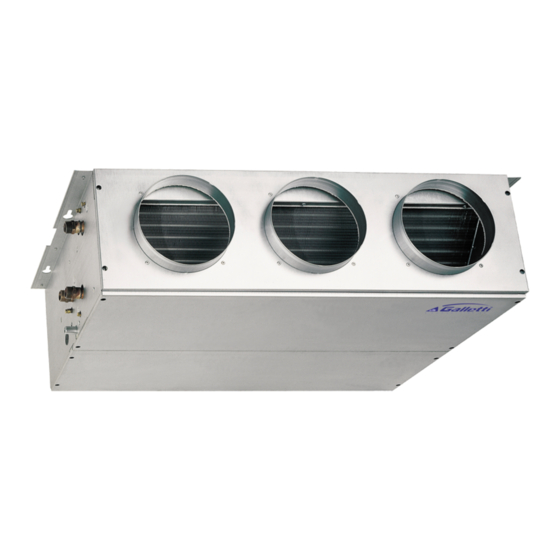
- Page 1 high pressure fan coils technical manual...
-
Page 2: Table Of Contents
INDEX DECLARATION OF CONFORMITY Main features ................pag. 2 Galletti S.p.A. with head offices in Via Romagnoli 12/A, 40100 Bentivoglio (Bologna) - Italy, declares under its own exclusive Versions and components ............. pag. 2 responsibility that the UTN range of air conditioning and hot-air POSSIBLE CONFIGURATIONS ............ -
Page 3: Possible Configurations
POSSIBLE CONFIGURATIONS AVAILABLE OPTIONS The wide and complete range of accessories completes the UTN air handling units as far as operation is concerned, adapting these units to any plant- VERTICAL INSTALLATION engineering requirements, from the solution with rectangular section channels to the one with round flexible ducts. -
Page 4: Rated Technical Data
RATED TECHNICAL DATA Fan speed Air flow High 1250 1250 1600 1600 2200 2200 3000 3000 Available static pressure High Total cooling capacity 2,80 3,20 3,90 4,80 6,20 7,00 7,80 8,82 11,90 13,70 16,40 18,30 Sensible cooling capacity 2,15 2,46 3,08 3,71 4,65... -
Page 5: Ventilation Features
VENTILATION FEATURES Legend: Fan speed: Available static pressure 3= high Air flow 2= medium 1= low UT66000806 - 02 All copying, even partial, of this manual is strictly forbidden... -
Page 6: All Copying, Even Partial, Of This Manual Is Strictly Forbidden
VENTILATION FEATURES Legend: Fan speed: Available static pressure 3= high Air flow 2= medium 1= low UT66000806 - 02 All copying, even partial, of this manual is strictly forbidden... -
Page 7: Accessories: Air Pressure Drop
VENTILATION FEATURES ACCESSORIES: AIR PRESSURE DROP Legend: Air flow Air pressure drop Qa [m 1000 1050 MAFO PCOF A* PCOF M** Qa [m 1000 1050 1100 1150 1200 MAFO PCOF A* PCOF M** Qa [m 1000 1100 1200 1300 1400 1500 1600 1700 1800 1900 2000 2100 2200 MAFO PCOF A* PCOF M**... -
Page 8: Sound Power Levels For Octave Band
VENTILATION FEATURES ACCESSORIES: AIR PRESSURE DROP The pressure drops shown below refer to accessories that are not Legend: affected by the various sizes of the thermal ventilating units. Air flow ∆Pa Pressure drops refer to the accessory itself and are not related to the Air pressure drop size of the thermal ventilating units. -
Page 9: Performances
PERFORMANCES COOLING CAPACITY Legend: Inlet air temperature D.B. Total cooling capacity Inlet air temperature W.B. Sensible cooling capacity Inlet water temperature Water flow rate Outlet water temperature Pressure drop on water side Air flow 25 /18 (51%) / Tbu ) °C / Tw °C 6/11... -
Page 10: 7 Performances
PERFORMANCES COOLING CAPACITY Legend: Inlet air temperature D.B. Total cooling capacity Inlet air temperature W.B. Sensible cooling capacity Inlet water temperature Water flow rate Outlet water temperature Pressure drop on water side Air flow 27 /19 (47%) / Tbu ) °C / Tw °C 6/11... -
Page 11: Heating Capacity
PERFORMANCES HEATING CAPACITY Legend: Inlet air temperature D.B. Heating capacity Inlet water temperature Water flow rate DPw Pressure drop on water side Outlet water temperature Air flow / Tbu ) °C / Tw °C 50 / 45 60 / 50 70 / 60 90 / 70 2410... -
Page 12: 7 Performances
PERFORMANCES HEATING CAPACITY Legend: Inlet air temperature D.B. Heating capacity Inlet water temperature Water flow rate DPw Pressure drop on water side Outlet water temperature Air flow / Tbu ) °C / Tw °C 50 / 45 60 / 50 70 / 60 90 / 70 2220... -
Page 13: Df Coil Heating Capacity
PERFORMANCES DF COIL HEATING CAPACITY Legend: Inlet air temperature D.B. Inlet water temperature Outlet water temperature Air flow Heating capacity Water flow rate DPw Pressure drop on water side °C 50 / 45 60 / 50 70 / 60 90 / 70 / Tw °C 1660... -
Page 14: Installation Suggestions
INSTALLATION SUGGESTIONS UTN units can be installed both vertically and horizzontally. Keep free space around the fan coil to allow proper operation of the unit and The UTN units are always supplied for the A-A placing. ordinary and extraordinary maintenance. If a different placing is needed the installer can modify it before mounting the Install the remote control panel, if any, in a position that can easily be reached unit (see chapter 3 "POSSIBLE CONFIGURATIONS"). -
Page 15: Dimensional Data
DIMENSIONAL DATA 6 fast-coupling slots AIR INTAKE condensate discharge - horizontal installation 6-A supply terms condensate discharge - vertical installation 6-B changeable during installation right-hand hydraulic attachments round pre-sheared element (φ 100 mm) for external air inlet AIR DELIVERY UTN 06 - UTN 08 - UTN 12 - UTN 16 UTN 06 UTN 08 UTN 12... -
Page 16: All Copying, Even Partial, Of This Manual Is Strictly Forbidden
DIMENSIONAL DATA 6 fast-coupling slots AIR INTAKE condensate discharge – horizontal installation 6-A supply terms condensate discharge – vertical installation 6-B changeable during installation right-hand hydraulic attachments round pre-sheared element (φ 100 mm) for external air inlet AIR DELIVERY UTN 22 - UTN 30 UTN 22 1174 1127... -
Page 17: Wiring Diagrams
WIRING DIAGRAMS Wiring diagram notes WARNING! Turn off the power supply before beginning any wiring Each fan-coil thermal-ventilating unit requires a switch (IL) on the feeder connections. line with a distance of at least 3 mm between the opening contacts, and a The dashed lines connections must be carried out by the installer. -
Page 18: All Copying, Even Partial, Of This Manual Is Strictly Forbidden
WIRING DIAGRAMS Wiring diagram notes WARNING! Turn off the power supply before beginning any wiring Each fan-coil thermal-ventilating unit requires a switch (IL) on the feeder connections. line with a distance of at least 3 mm between the opening contacts, and a The dashed lines connections must be carried out by the installer. -
Page 19: All Copying, Even Partial, Of This Manual Is Strictly Forbidden
WIRING DIAGRAMS Wiring diagram notes WARNING! Turn off the power supply before beginning any wiring Each fan-coil thermal-ventilating unit requires a switch (IL) on the feeder connections. line with a distance of at least 3 mm between the opening contacts, and a The dashed lines connections must be carried out by the installer. -
Page 20: All Copying, Even Partial, Of This Manual Is Strictly Forbidden
WIRING DIAGRAMS Wiring diagram notes WARNING! Turn off the power supply before beginning any wiring Each fan-coil thermal-ventilating unit requires a switch (IL) on the feeder connections. line with a distance of at least 3 mm between the opening contacts, and a The dashed lines connections must be carried out by the installer. -
Page 21: All Copying, Even Partial, Of This Manual Is Strictly Forbidden
WIRING DIAGRAMS Wiring diagram notes WARNING! Turn off the power supply before beginning any wiring Each fan-coil thermal-ventilating unit requires a switch (IL) on the feeder connections. line with a distance of at least 3 mm between the opening contacts, and a The dashed lines connections must be carried out by the installer. -
Page 22: All Copying, Even Partial, Of This Manual Is Strictly Forbidden
1 0W I R I N G D I A G R A M S W i r i n g d i a g r a m n o t e s W A R N I N G ! T u r n o f f t h e p o w e r s u p p l y b e f o r e b e g i n n i n g a n y w i r i n g c o n n e c t i o n s . - Page 23 1 0 W I R I N G D I A G R A M S W i r i n g d i a g r a m n o t e s W A R N I N G ! T u r n o f f t h e p o w e r s u p p l y b e f o r e b e g i n n i n g a n y w i r i n g c o n n e c t i o n s .
-
Page 24: Motors Electrical Data
a s s ( A ) a s s ( W ) hi g h 0, 820 UTN0 6- 0 6A m ed 0, 550 l ow 0, 400 hi g h 1, 210 UTN0 8- 0 8A m ed 0, 810 l ow 0, 700... -
Page 25: Accessories
ACCESSORIES MICRONET- Advanced microprocessor control MICROPRO e MICROPRO-D - Microprocessor control panels for ergo solution panels MICRONET is the control panel suitable for the Microprocessor control panels for in built (MICROPRO) connection to the ERGO SOLUTION. Microprocessor and wall (MICROPRO-D) installation complete with control panels for wall installation complete with fan fan speed selector, electronic thermostat and cooling speed selector, electronic thermostat and cooling /... -
Page 26: All Copying, Even Partial, Of This Manual Is Strictly Forbidden
ACCESSORIES TA - Wall mounted room thermostat PCOF - Connecting panel to Room thermostat for wall installation. flexible ducts Automatic regulation of the room temperature: Manufactured in galvanised sheet - only in the heating mode working on the fan motor steel, the PCOF connection panels assembly and on the regulating valve, if installed (ON/ are used to connect to air... -
Page 27: All Copying, Even Partial, Of This Manual Is Strictly Forbidden
ACCESSORIES KSC - Condensate removal kit GA / GAT - Vibration dampers This device allows to overcome displacements Manufactured in galvanized sheet in the condensate drain. steel, the GA/GAT connection The pump can drain water up to 8 l/h and it is panels are used to connect to completed by a non return valve on the rectangular ducts equipped with... -
Page 28: Maintenance
For safety reasons, before performing any maintenance or cleaning operations, turn off the equipment and cut voltage by turning the line switch. 40010 Bentivoglio (BO) Via Romagnoli, 12/a Tel. 051/8908111 Fax 051/8908122 www.galletti.it UT66000806 - 02 All copying, even partial, of this manual is strictly forbidden...
Need help?
Do you have a question about the UTN Series and is the answer not in the manual?
Questions and answers