Mark-10 F Series User Manual
Test frames
Hide thumbs
Also See for F Series:
- Quick start manual (2 pages) ,
- User manual (78 pages) ,
- Quick start manual (2 pages)

Related Manuals for Mark-10 F Series


Summary of Contents for Mark-10 F Series
- Page 1 Series TEST FRAMES Models: F105 | F305 | F505 | F505H F755 | F755S | F1505 | F1505S IntelliMESUR Software ® User’s Guide TABLE OF CONTENTS GlobalTestSupply www. .com Find Quality Products Online at: sales@GlobalTestSupply.com...
-
Page 2: Table Of Contents
Series F Test Frames + IntelliMESUR Software User’s Guide ® TABLE OF CONTENTS 1 OVERVIEW ..........................4 1.1 Intended purpose ......................4 1.2 Models F105 / F305 / F505 / F505H ................4 1.3 Models F755 / F755S / F1505 / F1505S ..............6 2 SAFETY .......................... - Page 3 Series F Test Frames + IntelliMESUR Software User’s Guide ® 8.2 Distance Limit ......................39 8.3 Break Limit ........................ 40 8.4 Load Hold ........................40 8.5 Cycle Test ......................... 40 9 CREATING A MULTI-STEP TEST ..................43 9.1 Multi-Step Overview ....................43 9.2 Step Types ........................
-
Page 4: Overview
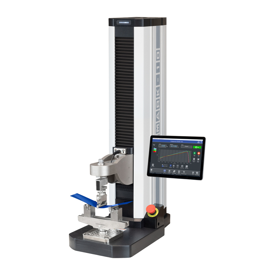
Series F Test Frames + IntelliMESUR Software User’s Guide ® 1 OVERVIEW 1.1 Intended purpose Series F test frames produce tension and compression forces. When combined with a force sensor and IntelliMESUR software, users can measure force and distance, set up a test, record, analyze, and output data. - Page 5 Series F Test Frames + IntelliMESUR Software User’s Guide ® 1.2.2 Physical features Note the following physical features. The user’s guide will reference this terminology. Model F305-IMT is shown below: Column Column Upper limit switch (lower limit switch not visible) Crosshead Tablet control Force...
-
Page 6: Models F755 / F755S / F1505 / F1505S
Series F Test Frames + IntelliMESUR Software User’s Guide ® 1.2.3 Installing the Column End Cap for F505H The end cap is shipped in a separate box within the main box for the F505H test frame. Line it up with the right end of the column, then install with the four included screws, as shown below: 1.3 Models F755 / F755S / F1505 / F1505S 1.3.1 Included items... - Page 7 Series F Test Frames + IntelliMESUR Software User’s Guide ® 1.3.2 Physical features Note the following physical features. The user’s guide will reference this terminology. Model F1505-IMT is shown below: Column cap Column Limit switches (not visible) Bellows Control panel bracket Control panel Force sensor...
-
Page 8: Safety
If using a grip or fixture from a supplier other than Mark-10, ensure that it is constructed of suitably rugged materials and components. -
Page 9: Emergency Stop
Series F Test Frames + IntelliMESUR Software User’s Guide ® 2. Ensure that the test frame is kept away from water or any electrically conductive liquids at all times. 3. Make sure the electrical outlet powering the test frame has local earth ground (3-prong connector). -
Page 10: Setup
Series F Test Frames + IntelliMESUR Software User’s Guide ® 3 SETUP 3.1 Intended Use Series F test frames with IntelliMESUR software are designed for tension and compression force measurement applications. The test frame applies force, while a force sensor measures the applied forces. -
Page 11: Connections And Outputs
Series F Test Frames + IntelliMESUR Software User’s Guide ® 3.5 Connections and outputs The following connections and outputs are supplied in the rear of the test frame, as shown in the illustration below: Auxiliary Limits For interfacing an external limit switch, such as an interlock for a shield door. -
Page 12: Installing Series Fs05 Force Sensors To Models F105 / F305 / F505 / F505H
Series F Test Frames + IntelliMESUR Software User’s Guide ® 3.6 Installing Series FS05 Force Sensors to Models F105 / F305 / F505 / F505H To avoid overload and damage, select a force sensor with sufficient capacity to accommodate the application. Series FS05 force sensors mount directly to the crosshead. -
Page 13: Installing Series R07 Force Sensors To Models F755 / F755S / F1505 / F1505S
Series F Test Frames + IntelliMESUR Software User’s Guide ® Grips and fixtures may be threaded onto the threaded shaft protruding from the bottom of the force sensor, for example: To avoid damage to the internal load cell or shaft, do not use tools to tighten grips or attachments onto the shaft. -
Page 14: Installing A Third-Party Force Sensor
Series F Test Frames + IntelliMESUR Software User’s Guide ® 3.9 Installing a Third-Party Force Sensor Before installing the sensor, refer to the Model PTA / PTAF user’s guide for complete instructions. 3.9.1 Models F105 / F305 / F505 / F505H Using the optional Model PTAF adapter, a third-party force sensor may be mounted to the test frame. -
Page 15: Installing The Intellimesur Control Panel
Series F Test Frames + IntelliMESUR Software User’s Guide ® 3.10 Installing the IntelliMESUR control panel For test frame part numbers ending in “-IMT”, for example Model F305-IMT, a Windows tablet with attached ball mount and mounting bracket are included, packaged separately. The mounting arm is pre-installed into the front right slot in the test frame column via two screws, as shown below: Loosen the knob sufficiently to slide the ball, mounted to the rear of the tablet, into the arm. -
Page 16: Installing Intellimesur
Series F Test Frames + IntelliMESUR Software User’s Guide ® 4 INSTALLING INTELLIMESUR 4.1 Hardware Requirements 4.1.1 Pre-configured tablet IntelliMESUR is pre-installed onto the tablet provided with “-IMT” model numbers, ex. F305-IMT. To ensure optimal performance for IntelliMESUR, do not install any additional applications onto the tablet. -
Page 17: Installation
1. Insert the installation flash drive into the device’s USB port, or download the zipped installation folder. Locate and double-click the file “setup.exe”. The screen appears as follows: 2. Accept the terms, then click Install. All required files will be installed, including the Mark-10 USB driver. When installation is complete, the screen appears as follows: 3. -
Page 18: Intellimesur Basics
5.1 Opening IntelliMESUR Ensure that the device is connected to the test frame with a USB cable. Then open IntelliMESUR. 5.1.1 Mark-10-supplied tablet Press the Power button. The tablet will boot directly into IntelliMESUR. If the tablet was asleep or hibernating, double-tap the IntelliMESUR icon. -
Page 19: Home Screen
Series F Test Frames + IntelliMESUR Software User’s Guide ® 5.2 Home Screen IntelliMESUR launches into the Home Screen, with the following selections: Open Test Recall a previously saved test. New Test Create a new test. Edit Test Edit the parameters of a previously saved test. Recall Test Data Recall data from previously saved test runs. - Page 20 If the test frame has been disconnected, then reconnected, select this button to restore communication. Exit Select to exit the software. If running IntelliMESUR on a Mark-10-supplied tablet, a prompt will offer the user two choices: Exit into Windows Exit and shut down the tablet...
-
Page 21: Settings
Series F Test Frames + IntelliMESUR Software User’s Guide ® 6 SETTINGS 6.1 Information Contains serial numbers, software and firmware versions, and other information about the equipment. The screen appears as follows: 6.2 User Management 6.2.1 Enabling User Login IntelliMESUR can be run with or without a user login. By default, User Login is not enabled. Make the appropriate selection in the following screen: When User Login is enabled, the User Login button is always present in the upper corner of the screen, as follows:... - Page 22 Series F Test Frames + IntelliMESUR Software User’s Guide ® Select this button to log out and log in as a new user. 6.2.2 User Permission Levels IntelliMESUR provides three user permission levels, summarized as follows: Operator Supervisor Administrator Manual Control Recall and run a test Create a test Create a report...
-
Page 23: Calibration
Enter the requested passwords. If the password has been forgotten, select Forgot Password. The screen appears as follows: IntelliMESUR automatically generates a request code. Supply this code to Mark-10 or a distributor, who will then provide a corresponding authorization code, which allow the user to reset the password. - Page 24 Series F Test Frames + IntelliMESUR Software User’s Guide ® Default Settings Load and Distance Units Select the desired units of measure. Note that not all units are supported by all force sensors. Refer to the force sensor’s specifications for list of supported units. Digital Filter The digital filter smooths out load readings in situations where there is mechanical interference in the work area or test sample.
-
Page 25: Overloads
Series F Test Frames + IntelliMESUR Software User’s Guide ® Date and Time Format Select the desired date and time format. The current date and time are linked to the Windows clock. To change the time on a touch-enabled device, press and hold the clock in the lower-right corner of the screen. If using a mouse, right-click, then select Adjust date/time. -
Page 26: Deflection Compensation
Series F Test Frames + IntelliMESUR Software User’s Guide ® Note: Overloads which may occur while the force sensor is disconnected from a Series F test frame, or while the test frame is powered off, are not recorded in Overload History. 6.6 Deflection Compensation Refer to the Calibration section for further information. -
Page 27: Load And Distance Measurement
Series F Test Frames + IntelliMESUR Software User’s Guide ® 7.1 Load and Distance Measurement Load and distance measurement are displayed as below: Load Load is displayed in the unit of measurement selected in Default Settings. Use the Mode button to toggle between three display modes: Load The real-time load. -
Page 28: Height / Length Offset
Series F Test Frames + IntelliMESUR Software User’s Guide ® Momentary Mode The crosshead will move only while selecting and holding down the Up or Down button. To set the speed, type the value into the box or drag the slider to the desired value, as shown below: Maintained Mode The crosshead will move continuously after selecting the Up or Down button. -
Page 29: Set Home
Series F Test Frames + IntelliMESUR Software User’s Guide ® 7.4 Set Home When Manual Control is accessed from an active test screen, instead of from the Home Screen, the Set Home button appears as follows: Selecting this button establishes the current crosshead position as Home. Refer to subsequent sections for more details on how this position relates to test configurations. - Page 30 Series F Test Frames + IntelliMESUR Software User’s Guide ® The Basic Test Wizard consists of four steps. Each stepped is grouped into panels containing settings. The four steps are as follows: 1. Pre-Test Setup 2. Test Setup 3. Results Setup 4.
- Page 31 Series F Test Frames + IntelliMESUR Software User’s Guide ® Set Home Establish the starting position of the crosshead as the Home position. You can auto-return to this position; this may be set in subsequent sections of the wizard. Height Mode To measure distance relative to a reference point established via the Height / Length Offset function in Manual Control, enable Height Mode.
- Page 32 Make the desired selection. Example prompts, as they appear during a test: Tell Prompt Ask Prompt For convenience in high-volume testing applications, a USB barcode scanner can be used to input a response (not available from Mark-10). TOC GlobalTestSupply www. .com Find Quality Products Online at: sales@GlobalTestSupply.com...
- Page 33 Series F Test Frames + IntelliMESUR Software User’s Guide ® Deflection Compensation Force sensors and test frames deflect under load, affecting the accuracy of distance measurements. Series F test frames and force sensors are compensated at the factory. To account for deflection within grips or fixtures associated with the test, IntelliMESUR provides a utility for additional compensation.
- Page 34 Series F Test Frames + IntelliMESUR Software User’s Guide ® 8.1.2 Load Limit Setup Basic Setup Panel The screen appears as follows: Specify the target load and direction, then specify the test speed. To collect continuous data points for each run, enable Display Results. Results may still be saved even if Display Results is disabled.
- Page 35 Series F Test Frames + IntelliMESUR Software User’s Guide ® from a grip. Specify a drop in load from the maximum value (Break % Drop). IntelliMESUR starts monitoring for a break after the Break Threshold has been reached. 8.1.3 Results Setup IntelliMESUR can calculate a number of results and calculate statistics for results over multiple runs.
- Page 36 Series F Test Frames + IntelliMESUR Software User’s Guide ® Distance Results Load Averaging Load Averaging dynamically captures data points and averages the result over a distance or period of time. This requirement is common in peel testing and coefficient of friction testing applications.
- Page 37 Series F Test Frames + IntelliMESUR Software User’s Guide ® Other Optionally include the date and time of the test, along with corresponding crosshead speed. 8.1.4 Post-Test Setup In this step, a number of post-test preferences and settings can be configured. Basic Setup Return Home Crosshead returns to the prevously set Home position at the end of the test.
- Page 38 Series F Test Frames + IntelliMESUR Software User’s Guide ® Invert IntelliMESUR processes force, distance, and time data as follows: Tension forces are plotted as negative values. Compression forces are plotted as positive values. Upward or rightward motion is displayed as increasing distance values, while downward ...
-
Page 39: Distance Limit
Series F Test Frames + IntelliMESUR Software User’s Guide ® Folders Browse to the desired folder locations for test configuration files, data, results, and reports. Select Next to complete the test setup. When prompted, select Save & Run, Save & Go Home, or Cancel. -
Page 40: Break Limit
Series F Test Frames + IntelliMESUR Software User’s Guide ® Test Direction Select upward or downward motion for vertical test frames, or rightward and leftward for model F505H. Target Distance Crosshead will stop at the specified distance. 8.3 Break Limit Break Limit tests are useful for a wide variety of destructive applications, including peel testing, wire crimp pull-off testing, tensile testing, and many others. - Page 41 Series F Test Frames + IntelliMESUR Software User’s Guide ® Basic Settings Cycle Type Select number of cycles, or specify a period of time, in hours, minutes, and seconds. Up Stroke / Down Stroke Settings Up Stroke (crosshead moving up or right) and Down Stroke (crosshead moving down or left) settings may be set independently of each other.
- Page 42 Series F Test Frames + IntelliMESUR Software User’s Guide ® Distance Specify as desired. Limit Switch Crosshead stops when it reaches the upper physical limit switch. Speed Specify the crosshead speed. Dwell Time Specify how much time the crosshead waits at the target before reversing. Exception Limits Specify exception limits for each stroke independently.
-
Page 43: Creating A Multi-Step Test
Series F Test Frames + IntelliMESUR Software User’s Guide ® 9 CREATING A MULTI-STEP TEST A Multi-Step test can string together any number of basic test functions, data collection steps, data zero steps, cycling, and promps. Steps may be placed in the desired order, then re-ordered as desired. 9.1 Multi-Step Overview The initial screen appears as follows: Available steps are listed in the left side of the screen, and may be inserted into the step sequence to the... - Page 44 Series F Test Frames + IntelliMESUR Software User’s Guide ® To insert a step, highlight an existing step. It will become blue. Then click the desired step. It will be inserted after the currently selected step. An example test is below: The step sequence must contain the three steps listed above: Pre-Test, Results, and Post-Test.
-
Page 45: Step Types
Series F Test Frames + IntelliMESUR Software User’s Guide ® Distance Results: 9.2 Step Types Multi-step tests build upon the same functions as in Basic Tests, while separating out datum, prompting, zero, and go-home functions. Preload is not integrated into steps as in Basic Tests. Instead, a preload must be manually configured as a separate Load Limit step, followed by a Zero step. - Page 46 Series F Test Frames + IntelliMESUR Software User’s Guide ® 9.2.3 Loop The Loop function repeats a range of steps. Insert this step after the last step to be repeated. Select either a number of loops or a time duration for constant looping. Then, enter the Starting Step number.
- Page 47 Series F Test Frames + IntelliMESUR Software User’s Guide ® 9.2.6 Data A Data step saves the current load and/or distance value in the Results table. Make the desired selections. 9.2.7 Zero A Zero step zeroes the load and/or distance. Make the desired selections. 9.2.8 Home A Home step returns the crosshead to the Home position at the specified speed.
-
Page 48: Running A Test
Series F Test Frames + IntelliMESUR Software User’s Guide ® 10 RUNNING A TEST 10.1 Favorite Tests Saved tests may be designated as favorites, for quick access when selecting Open Test from the Home screen. The screen appears as follows: 10.1.1 Creating a Favorite Select Assign Favorite, then select the desired box location. - Page 49 Series F Test Frames + IntelliMESUR Software User’s Guide ® Browse to the desired file, then select Open. Optionally associate an image with the favorite box by making the appropriate selection to the next screen: If selecting Yes, browse to the desired image, then select Open. The screen appears as follows: TOC ...
- Page 50 Series F Test Frames + IntelliMESUR Software User’s Guide ® 10.1.2 Unassigning a Favorite Select Unassign Favorite, then select the desired test. 10.1.3 Edit a Test Select Edit Test, then select the desired test. 10.1.4 Opening a Test Select a previously assigned favorite, or select Other Test to browse for other tests not assigned as favorites.
-
Page 51: Graph View
Series F Test Frames + IntelliMESUR Software User’s Guide ® 10.2 Graph View The screen appears as follows: Multiple runs may be viewed on the graph at the same time. If Overlay Runs on Graph is selected in the test setup, the screen appears as follows: Select the desired runs to view. - Page 52 Series F Test Frames + IntelliMESUR Software User’s Guide ® 10.2.1 Basic Information Along the top of the screen, the following information is always displayed: Batch counter – if Batch is enabled in the test setup, the current run number and batch size are displayed.
-
Page 53: Results View
Series F Test Frames + IntelliMESUR Software User’s Guide ® The cursor will snap to the closest plot when multiple runs are displayed simultaneously. Zoom To zoom by hand, pinch fingers to zoom in and out. To zoom in via mouse, click and drag to create a zoom window. - Page 54 Series F Test Frames + IntelliMESUR Software User’s Guide ® Below is an example of a one-loop, two-cycle multi-step test: The following additional information is displayed in a multi-step test versus a basic test: Run No. Run number. Step No. Indicates the step number within the multi-step sequence.
- Page 55 Series F Test Frames + IntelliMESUR Software User’s Guide ® Since any number of loops may be configured in a multi-step test, Loop No. identifies the loop within the test. Cycle Count refers to the cycle number within a specific Loop step. Overall Run Status When there is more than one pass/fail status per run, an additional row is added to the Results table, labeled Overall Run.
- Page 56 Series F Test Frames + IntelliMESUR Software User’s Guide ® The Status cell will be updated as follows, as an example: Note: once a run has been invalidated, it cannot be re-validated. 10.3.4 Results Processing Save Results Save results to a file, which can later be recalled. IntelliMESUR automatically assigns a file name containing the test name, followed by a time stamp.
-
Page 57: Data Details View
Series F Test Frames + IntelliMESUR Software User’s Guide ® 10.4 Data Details View Data Details view tabulates raw data for a run, including reading number, load, distance, and elapsed time. The screen appears as follows: If Overlay Runs on Graph is selected in the test setup, data for up to 10 runs may be viewed by making the appropriate selection along the left side of the screen. -
Page 58: Creating A Report
Series F Test Frames + IntelliMESUR Software User’s Guide ® 10.5 Creating a Report A report may be created, containing the results, graph, equipment used, and other pertinent information. The screen appears as follows: 10.5.1 Creating a Template Open a previously saved template by selecting Open Template, or create a new one. As shown in the above image, any of the following information may be specified in a report template, as desired: TOC ... - Page 59 Series F Test Frames + IntelliMESUR Software User’s Guide ® Company Logo Browse for a company logo, or other image, and select the desired alignment at the top of the report. Test Image If the test is saved in Favorites with an associated image, that same image is included in the report template by default.
- Page 60 Series F Test Frames + IntelliMESUR Software User’s Guide ® TOC GlobalTestSupply www. .com Find Quality Products Online at: sales@GlobalTestSupply.com...
-
Page 61: Recalling Previous Data
11 CALIBRATION 11.1 Force Sensor Calibration Mark-10 recommends calibrating force sensors at least once per year. Series FS05 and R07 force sensors may be calibrated while installed on a Series F test frame, or may be removed the frame and calibrated with a Mark-10 Model M5I or Model M7I indicator. - Page 62 Series F Test Frames + IntelliMESUR Software User’s Guide ® of whether calibration takes place. This accounts for situations in which the force sensor accuracy has been verified to within specification and re-calibration is not necessary. Note that the due date may be modified regardless of whether the calibration date was updated.
- Page 63 Series F Test Frames + IntelliMESUR Software User’s Guide ® 4. The force sensor can be calibrated at up to 10 points in each direction. Enter the number of calibration points for each direction (tension and compression). At least one point must be selected for each direction.
- Page 64 Series F Test Frames + IntelliMESUR Software User’s Guide ® Zero the indicator associated with the master load cell. Engage the calibration fixtures, and ensure that there is no load applied to the force sensor. Then select Next. Apply the indicated compression load using the crosshead motion controls. The load value defaults to even intervals.
- Page 65 Select Finish to complete the calibration, or Cancel to exit without saving the calibration. 11.1.2 Calibrating with a Mark-10 Indicator Series FS05 and R07 force sensors may be removed and calibrated in a different location with a Mark-10 model M5I or M7I indicator with minimum firmware version of 2.2.8.
-
Page 66: Speed And Distance Calibration
11.2 Speed and Distance Calibration Mark-10 recommends verification of speed and distance accuracy once per year. Note that no adjustments may be made. Calibration is offered by Mark-10, as well as certain distributors and third- party laboratories. 11.3 Test Frame Deflection Compensation Load cells within force sensors deflect under load. -
Page 67: Maintenance & Service - Models F105 / F305 / F505 / F505H
Series F Test Frames + IntelliMESUR Software User’s Guide ® 12 MAINTENANCE & SERVICE – MODELS F105 / F305 / F505 / F505H 12.1 Physical Maintenance Series F test frames should be operated in a dry and clean area. Under these circumstances the main consideration is lubrication of the ball screw and slider. - Page 68 Series F Test Frames + IntelliMESUR Software User’s Guide ® 12.1.2 Slider lubrication – once per year Slider lubrication frequency should increase when used in in adverse conditions. Follow these instructions: Two people are recommended for this procedure, due to the risk of tipping. 1.
- Page 69 ® 3. Remove the base, then remove the two screws on the right, as shown below: 4. Remove the Mark-10 logo strip, then remove all screws from the side of the test frame, as shown below: 5. Locate the grease receptacle on the slider, as identified below: TOC ...
- Page 70 2. Attempt to loosen subcomponents of the test frame (ex. fasteners, brackets, etc.). All components should be firmly attached. If any looseness is detected, stop using the test frame and contact Mark-10 or a distributor for instructions. TOC GlobalTestSupply www.
-
Page 71: Removing The Motor Drive Unit (Mdu)
The MDU is the self-contained location of most of the test frame’s electronics, and is designed for quick removal and replacement in the event of service or repair. If requested by Mark-10 or a distributor to remove and/or replace the MDU, follow these instructions: 1. -
Page 72: Maintenance & Service - Models F1505 / F1505S / F755 / F755S
Series F Test Frames + IntelliMESUR Software User’s Guide ® 13 MAINTENANCE & SERVICE – MODELS F1505 / F1505S / F755 / F755S 13.1 Physical Maintenance Series F test frames should be operated in a dry and clean area. Under these circumstances the main consideration is lubrication of the ball screw and slider. - Page 73 Series F Test Frames + IntelliMESUR Software User’s Guide ® 13.1.2 Slider lubrication As with the ball screw, periodic lubrication of the slider improves performance and increases the longevity of test frame components. Frequency depends on environmental conditions and usage. Follow these instructions for proper slider lubrication: 1.
-
Page 74: Removing The Motor Drive Unit (Mdu)
The MDU is the self-contained location of most of the test frame’s electronics, and is designed for quick removal and replacement in the event of service or repair. If requested by Mark-10 or a distributor to remove and/or replace the MDU, follow these instructions: 1. -
Page 75: Accessory Installation
When a safety shield is used, the standard emergency stop switch is located within the enclosure, preventing its use during a test. An external limit switch is, therefore, included with Mark-10 safety shields. A corresponding connector is pre-installed on Models F755, F755S, F1505, and F1505S test frames. For Models F105, F305, and F505, the connector must be installed in the rear of the MDU. - Page 76 Series F Test Frames + IntelliMESUR Software User’s Guide ® 3. Remove the back panel from the MDU housing with the four screws, highlighted below: 4. Route the two wires from the rear of the connector through the hole, as shown below: 5.
- Page 77 Series F Test Frames + IntelliMESUR Software User’s Guide ® 6. Install the connector to the housing by inserting the spacer over the body of the connector, then tightening the nut, as shown below: 7. Reassemble the MDU and reinstall, as instructed in earlier sections. 8.
-
Page 78: Column Extension Installation - F105 / F305 / F505 / F505H
Series F Test Frames + IntelliMESUR Software User’s Guide ® 3. Plug the interlock cable into the corresponding connector in the rear of the test frame column, labeled “Auxiliary Limits”, as shown in the Connections and Outputs section. 4. Route all cables, such as the test frame power cable and control panel cable, underneath the shield, as shown below. - Page 79 Carefully remove the base from the frame. Refer to the image below: 14.2.2 Retrofitting a Mark-10 AC1094-1 / -2 / -3 single column extension (optional) If a single column extension is ordered upfront, it is pre-installed at the factory and shipped assembled.
- Page 80 Series F Test Frames + IntelliMESUR Software User’s Guide ® 3. Attach the top flange to the bottom of the test frame column utilizing the 6 supplied screws, as shown in the image below: 4. Position the test frame vertically and reinstall the sheet metal covers, as shown below: Vertical column extensions present an increased tipping hazard.
-
Page 81: Installing A Double Column Extension - F105 / F305 / F505
Series F Test Frames + IntelliMESUR Software User’s Guide ® 14.3 Installing a double column extension – F105 / F305 / F505 Models AC1095-1 / -2 / -3 column extensions are shipped fully assembled. To mount the test frame to the assembly, locate the 6 thru holes, match them up to the corresponding threaded holes on the underside of the frame, and install the screws. -
Page 82: Updating Software And Firmware
To update, select Update Software or Update Firmware the Settings screen. The screen appears as follows: The file will be supplied by Mark-10 or a distributor. Save the file to the desired file location, browse to it, then select the Update button at the bottom of the screen. -
Page 83: Specifications & Dimensions
Series F Test Frames + IntelliMESUR Software User’s Guide ® 16 SPECIFICATIONS & DIMENSIONS 16.1 Specifications F105 F305 F505 F505H F755 F755S F1505 F1505S 100 lbF 300 lbF 500 lbF 750 lbF 1,500 lbF Load capacity*: [0.5 kN] [1.5 kN] [2.2 kN] [3.4 kN] [6.7 kN]... -
Page 84: Dimensions
Series F Test Frames + IntelliMESUR Software User’s Guide ® 16.2 Dimensions 16.2.1 Models F105 / F305 / F505 TOC GlobalTestSupply www. .com Find Quality Products Online at: sales@GlobalTestSupply.com... - Page 85 Series F Test Frames + IntelliMESUR Software User’s Guide ® 16.2.2 Model F505H TOC GlobalTestSupply www. .com Find Quality Products Online at: sales@GlobalTestSupply.com...
- Page 86 Series F Test Frames + IntelliMESUR Software User’s Guide ® 16.2.3 Models F755 / F755S / F1505 / F1505S F755 F755S F1505 F1505S 50.85 33.39 51.35 33.89 [1291.6] [848.1] [1304.3] [860.9] 8.13 – 40.13 8.13 – 22.33 8.13 – 40.13 8.13 –...
- Page 87 Series F Test Frames + IntelliMESUR Software User’s Guide ® 16.2.4 Models AC1095-1 / AC1095-2 / AC095-3 Double Column Extensions 8.79 6.00 AC1095 [223.3] [152.4] 14.79 12.00 AC1095-1 [375.7] [304.8] 26.79 24.00 AC1095-2 [680.5] [609.6] TOC GlobalTestSupply www. .com Find Quality Products Online at: sales@GlobalTestSupply.com...
- Page 88 Series F Test Frames + IntelliMESUR Software User’s Guide ® 16.2.5 Model AC1086 Safety Shield TOC GlobalTestSupply www. .com Find Quality Products Online at: sales@GlobalTestSupply.com...
- Page 89 User’s Guide ® Mark-10 Corporation has been an innovator in the force and torque measurement fields since 1979. We strive to achieve 100% customer satisfaction through excellence in product design, manufacturing and customer support. In addition to our standard line of products we can provide modifications and custom designs for OEM applications.
Need help?
Do you have a question about the F Series and is the answer not in the manual?
Questions and answers