Table of Contents
Advertisement
Quick Links
Advertisement
Table of Contents

Related Manuals for GeoSIG AC-23


Summary of Contents for GeoSIG AC-23
- Page 1 User Manual AC-23 Accelerometer Author: Serge Rudaz Checked: Markus Epp Approved: Johannes Grob Distribution: GeoSIG Ltd (1), Customer on request GeoSIG Ltd, Wiesenstrasse 39, 8952 Schlieren, Switzerland Phone: + 41 44 810 2150, Fax: + 41 44 810 2350 info@geosig.com, www.geosig.com...
- Page 2 Copyright Notice No part of this document may be reproduced without the prior written consent of GeoSIG Ltd. Software described in this document is furnished under a license and may only be used or copied in accordance with the terms of such a license.
-
Page 3: Table Of Contents
AC-23 Accelerometer User Manual 11.08.2022 / V17 3 / 15 TABLE OF CONTENTS WARNINGS AND SAFETY..........................3 BASIC SPECIFICATIONS ........................4 ELECTRICAL CONNECTOR ........................4 3.1 B 623........................... 4 INDER ERIE 3.2 B 423........................... 5 INDER ERIE 3.3 C ........................ 5... -
Page 4: Basic Specifications
AC-23 Accelerometer User Manual 11.08.2022 / V17 4 / 15 1 Basic Specifications Sensor Series AC-23 Input range Acceleration, ±0.2, ±0.5, ±1.0 g, ±2.0 g or ±4.0 g Output range 0 ± 10 Volt differential output OR 0 ± 5 Volt differential output OR 2.5 ±... -
Page 5: Binder Serie 423
AC-23 Accelerometer User Manual 11.08.2022 / V17 5 / 15 Binder Serie 423 GeoSIG P/N #J_CIR.012.010.M Binder Serie 423 P/N 99 5629 00 12 Figure 2, Binder Serie 423 connector Cable gland nut has to be determined as per cable external diameter and must be separately ordered. It has also to provide the cable shield connection to connector case. -
Page 6: Mounting
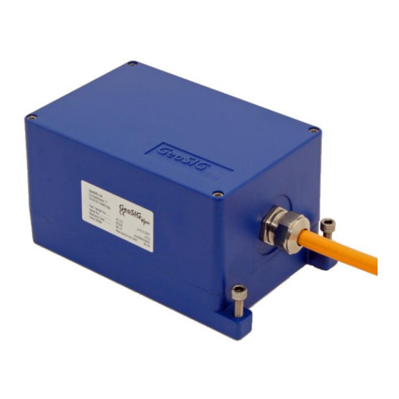
AC-23 Accelerometer User Manual 11.08.2022 / V17 6 / 15 3 Mounting Figure 2, AC-2X housing Small size and single bolt attachment allow the AC-2X to be easily installed saving installation time. Levelling is accomplished via three-point levelling screws. Do not overtighten the three-point levelling mechanism. This may damage the sensor. -
Page 7: Theory Of Operation
STRONG-MOTION earthquake survey, monitoring and research. This sensor is well suited for applications where a high sensitivity is required. The AC-23 sensor can be optionally installed into a rugged protective housing. This optional protective housing is in stainless steel for optimal environmental resistance. As option, the protective housing could be executed with an IP68 grade for free field location where the possibility exists of housing submersion. -
Page 8: Electrical Configuration
AC-23 Accelerometer User Manual 11.08.2022 / V17 8 / 15 The geophone is connected in a resistor bridge, driven by a feedback amplifier, which applies the amplified bridge differential signal in opposite polarity. The bridge is balanced during calibration. The test-line shifts the voltage at one side of the bridge, which produces a current flow in the geophone. -
Page 9: Offset Adjustment
AC-23 Accelerometer User Manual 11.08.2022 / V17 9 / 15 6 Offset Adjustment Offset Adjust Pin 12 Pin 1 Figure 7, Offset potentiometer location After the new full scale has been selected, the offset must be checked and eventually the potentiometer °... -
Page 10: Mounting (Downhole Sensor)
AC-23 Accelerometer User Manual 11.08.2022 / V17 10 / 15 8 Mounting (downhole sensor) The sensor must be installed in a 3-inch inclinometer tube. At least a 100 mm borehole must be drilled. Depending on the soil condition, it could be required to drill a higher dimension hole and to implement a 120 mm PVC casing to insure a free path when the inclinometer tube is inserted in the borehole. -
Page 11: Inclinometer Tube Installation
AC-23 Accelerometer User Manual 11.08.2022 / V17 11 / 15 8.2 Inclinometer tube installation Note: Do not scale the drawing. The number of sections is only an example. Inclinometer tube in 3 meters section. Sealing (concrete mix) of tube Coupling... -
Page 12: Sensor Installation
AC-23 Accelerometer User Manual 11.08.2022 / V17 12 / 15 8.3 Sensor installation Note: Do not scale the drawing. The number of sections is only an example. Cable The maximum water level above sensor must maximum 50 meters. Concrete sealing of sensor. -
Page 13: Inclinometer Casing Assembly
The water level in the inclinometer tube should be maximum 50 meters, including fast elevation due to heavy rain. It is recommended to use the optional assembly kit that GeoSIG can provide (optional) with the inclinometer tube. It will insure a perfect sealing of the tube elements and would avoid concrete mix to enter the tube. - Page 14 AC-23 Accelerometer User Manual 11.08.2022 / V17 14 / 15 The following elements will be inserted in the borehole: Torpedo Figure 12 (the sensor and its cable) Figure 13 Guiding system Figure 14 Inclinometer tube GS_AC-23_UserManual_V17...
-
Page 15: Axis Orientation
AC-23 Accelerometer User Manual 11.08.2022 / V17 15 / 15 8.5 Axis orientation Z axis Engraved X axis mark Y axis Figure 15, Down hole axis orientation Before the sensor is inserted in the inclinometer tube, the guiding system must be mounted bellow it. The guiding system must be orientated before the insertion.
Need help?
Do you have a question about the AC-23 and is the answer not in the manual?
Questions and answers