GeoSIG GMS plus User Manual
Hide thumbs
Also See for GMS plus:
- User manual (150 pages) ,
- Faq (8 pages) ,
- Quick user manual (2 pages)

Related Manuals for GeoSIG GMS plus


Summary of Contents for GeoSIG GMS plus
- Page 1 User Manual GeoSIG Ltd, Wiesenstrasse 39, 8952 Schlieren, Switzerland Phone: + 41 44 810 2150, Fax: + 41 44 810 2350 info@geosig.com, www.geosig.com...
- Page 2 Copyright Notice No part of this document may be reproduced without the prior written consent of GeoSIG Ltd. Software described in this document is furnished under a license and may only be used or copied in accordance with the terms of such a license.
-
Page 3: Table Of Contents
3 / 124 Table of Contents Applicability of This Manual ....................7 Warnings and Safety ......................7 GeoSIG Cybersecurity Recommendations ................ 10 Symbols and Abbreviations ....................12 1. Introduction ........................13 2. Incoming Inspection ....................... 13 2.1. Damage during shipment ........................13 2.2. - Page 4 9.4.4. Requests ............................58 9.5. Data Explorer ............................59 9.6. Help ...............................60 9.6.1. Online Help ............................60 9.6.2. Contact GeoSIG Service ........................60 10. Detailed Configuration of the Instrument ..............61 10.1. Switch ON and OFF the instrument ....................61 10.2. General Comments to the Configuration .....................61 10.2.1.
- Page 5 10.9.1. In the Web Interface or by GeoDAS .................... 96 10.9.2. Via Local Serial Console ......................97 10.9.3. Time synchronization ......................... 101 10.10. GeoSIG Options ..........................102 10.10.1. Via Local Serial Console......................102 10.11. Other Options in the Instrument Main Menu ................... 103 10.11.1.
- Page 6 Table 9. Explanation table structure ........................ 63 Table 10. Channel configuration menu structure..................... 66 Table 11. LSB of all GeoSIG sensors ......................67 Table 12. Data streaming configuration menu structure ................. 71 Table 13. Trigger configuration menu structure ....................77 Table 14.
-
Page 7: Applicability Of This Manual
GMS Instruments are constantly being improved. Although the manual you receive along with your instrument corresponds to the actual software versions, you are advised to check the GeoSIG web page periodically for the most recent version of this document, and especially after performing any software upgrades. - Page 8 In addition there is a non-rechargeable button battery (backup battery) on the circuit board of the instrument. NEVER use any battery other than the ones supplied or approved in writing by GeoSIG. An external power module, which is an optional accessory, is also usually shipped with the instrument.
- Page 9 Therefore GeoSIG cannot guarantee a SD or compact flash card will work in a GeoSIG instrument unless it is purchased through GeoSIG. The SD and compact flash cards provided by GeoSIG are tested and certified in house to work with the related GeoSIG instrument and industrial rated for harsh environment conditions as extreme temperatures, shock, and vibration.
-
Page 10: Geosig Cybersecurity Recommendations
20.06.2017 / V21 GeoSIG Cybersecurity Recommendations GeoSIG instruments, as described in their documentation, have built-in security and safety features against unauthorised access or use. However, ultimately it is the user’s responsibility to ensure the safe and secure usage of our instruments based on their actual implementation. No factory delivered solution can fit each and every possible scenario. - Page 11 10. Software / Firmware updates Networked devices must only run software/firmware that are updated according to supplier’s guidelines. A periodical check of any available updates from the supplier must be sought. Please contact GeoSIG Ltd if you require any further advice or clarification. GS_GMSplus_UserManual_V21...
-
Page 12: Symbols And Abbreviations
GMSplus User Manual 12 / 124 20.06.2017 / V21 Symbols and Abbreviations Analog to Digital Converter Main processor Bootloader First program executed when unit starts Compact Flash, memory card using Flash memory Compact Flash See CF Digital Signal Processor in charge of controlling the ADCs Earthquake Early Warning Flash Program storage memory device. -
Page 13: Introduction
If GeoSIG receives notice of such defects during the warranty period, GeoSIG shall at its option either repair (at factory) or replace free of charge hardware and software products that prove to be defective. If GeoSIG is unable, within a reasonable time, to repair or replace any cabinet to a condition as warranted, the buyer shall be entitled to a refund of the purchase price upon return of the cabinet to GeoSIG. -
Page 14: Storage (Instrument Shelf Life)
GMSplus User Manual 14 / 124 20.06.2017 / V21 3. Storage (Instrument Shelf Life) In case the instrument is stored, the batteries have to be maintained according to the storage duration. Period of External Instrument is Main battery Real Time Clock time power supply operating... -
Page 15: Description
GMSplus User Manual 20.06.2017 / V21 15 / 124 Figure 1. Position of JMP_BBATT 4. Description 4.1. Housing The instrument is a housing mounted with a base plate. The base plate is fixed on ground and levelled one time during installation, then the instrument can be replaced without need for levelling. Figure 2. -
Page 16: Base Plate
Please ensure that the vents are not covered and that the instrument is not placed in a confined area without adequate ventilation. GeoSIG will not accept any responsibility for the safe operation of the battery or any safety related consequences that may result from using the battery. -
Page 17: Standard External Connectors
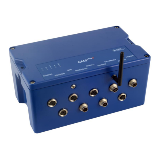
GMSplus User Manual 20.06.2017 / V21 17 / 124 Wi-Fi WiSync SENSOR 1 SERIAL POWER SENSOR 2 INTERCON MODEM ALARM Figure 5. Instrument with all connectors. Antennas are not mounted. 4.4.1. Standard External Connectors These connectors always will be assembled: POWER Connection to the power supply module of the instrument or to an external battery. -
Page 18: Optional External Connectors
GMSplus User Manual 18 / 124 20.06.2017 / V21 Mating Type: Binder Series 423, cable connector female, 5 pole 4.4.1.2. ETHERNET Connector Description Detection if cable is connected, to be connected to GND inside the cable RXD+ RXD- TXD+ TXD- Shield / GND Shield / GND Mating Type:... - Page 19 GMSplus User Manual 20.06.2017 / V21 19 / 124 INTERCON Connection to the interconnection network allowing common time and common triggering. MODEM Connection to analog phone line for the internal analog modem. ALARM Contacts of the internal alarm relays 4.4.2.1. SENSOR Connectors Description S_Test, Calibration Test Pulse Power, 12 VDC...
- Page 20 GMSplus User Manual 20 / 124 20.06.2017 / V21 4.4.2.2. ALARM Connector Standard Configuration Pin 1 Seismic 1 3 isolated relay contacts Pin 2 Pin 3 Seismic 2 Pin 4 Pin 5 System Fault Pin 6 Optional Configuration Seismic 1 Pin 1 4 relay contacts with common pin...
-
Page 21: Optional External Antennas
Desktop / Notebook 5. GMSplus series is a highly advanced unit with many options such as portability set, seismometer control, external on/off button, transport case etc, not shown here, please contact GeoSIG for further information 6. Optional supply and connections may require third party devices and/or services which may not typically be provided by GeoSIG. -
Page 22: Internal Connector
GMSplus User Manual 22 / 124 20.06.2017 / V21 4.4.5. Internal Connector The instrument is equipped with an internal RS-232 connector giving access to the console. A standard RS- 232 extension cable (straight, female-male) can be used to connect to a computer Figure 7. -
Page 23: Detail Description
GMSplus User Manual 20.06.2017 / V21 23 / 124 4.5.1. Detail Description Unit is OFF Instrument is starting up Normal operation of main program Main program is stopped Instrument is shutting down Figure 9. RUN indicator EVENT No event stored in CF and not recording. - Page 24 GMSplus User Manual 24 / 124 20.06.2017 / V21 LINK No link to the data server Connection to data server Instrument is connecting to interrupted the data server Link to data server OK, no communication Link to data server OK, communication ongoing Figure 11.
-
Page 25: Internal Batteries
GMSplus User Manual 20.06.2017 / V21 25 / 124 File Checkup At startup, three LEDs (yellow, blue and red) may flash synchronously for some while, which indicates that firmware is performing the full check of all files stored on the compact flash card. The process may take longer if there are many files collected. -
Page 26: Backup Battery
GMSplus User Manual 26 / 124 20.06.2017 / V21 4.6.2. Backup battery The backup battery is used to maintain time in the instrument when it is powered off. It requires the following specifications: Description Specification Nominal Voltage Capacity 285 mAh / 270 mAh Cell diameter 24.5 mm Cell height... -
Page 27: Supplied And Optional Accessories
GMSplus User Manual 20.06.2017 / V21 27 / 124 4.8. Supplied and Optional Accessories 4.8.1. Standard Supplied Accessories The following parts will be included in a shipment additional to the instrument: Fixation baseplate with levelling feet Screw and anchor bolt for fixation ... -
Page 28: Installation
GMSplus User Manual 28 / 124 20.06.2017 / V21 5. Installation This section lists the procedures involved in installation of the Instrument. The procedures will be outlined as steps to be performed in the field or in-house prior to deploying the instrument in the field. 5.1. -
Page 29: Communication Considerations
Contact GeoSIG or your local representative for more information. Typically it is required to connect the baseplate to the local earth to avoid or minimise 50/60 Hz distortions in the signal by surrounding power lines. -
Page 30: Orientation, Levelling And Calibration Of The Sensor
5.1.2. Optionally the instrument can be directly powered by an external battery or a 24 VDC or 48 VDC line. Please contact GeoSIG for more details. 5.2.5. Installing other Components, Options, Accessories For installation of other components options or accessories please refer to the specified option manual. -
Page 31: First Start And Communication Setup
GMSplus User Manual 20.06.2017 / V21 31 / 124 5.3. First Start and Communication Setup With the instrument correctly fixed on the ground through the fixation plate please proceed with chapter 7 for the first start-up and configuration. GS_GMSplus_UserManual_V21... -
Page 32: Principle Of Operation Of The Instrument
GMSplus User Manual 32 / 124 20.06.2017 / V21 6. Principle of Operation of the Instrument This chapter gives an overview about the normal operation of the instrument in a network or as a standalone unit. 6.1. Normal Operation During normal operation the instruments are installed on sites and connected to a data server over Ethernet or Internet. - Page 33 GMSplus User Manual 20.06.2017 / V21 33 / 124 Figure 17. Upload of seismic events and download of requests from the server All instruments will create an event at the time listed inside the data request and extract these data out of the ringbuffer data.
-
Page 34: Firmware And Configuration Upgrade
GMSplus User Manual 34 / 124 20.06.2017 / V21 6.3. Firmware and Configuration Upgrade In case of a firmware upgrade, the new firmware can be easily put on the server. All instruments will recognise the new firmware during the next server check-up, download and install it. See chapter 12 for details about the firmware upgrade. -
Page 35: Quick Start Up
In case there is no LAN available, the Ethernet cable can be connected directly to a computer. For this a crossed Ethernet cable is needed; please contact GeoSIG. Nevertheless in modern computers normally it works as well with the supplied patch cable. - Page 36 GMSplus User Manual 36 / 124 20.06.2017 / V21 Press <Ctr> + ‘Z’ as soon the following message appears on the console to enter the test mode. GMSplus s/n 100582. Firmware in the Linux image: 21.11.00 ################################################# ###### Test and Initial Configuration Mode ###### ################################################# Press Ctrl+Z to enter the test mode..
-
Page 37: No Stations Configured At First Start Up
The following steps require GeoDAS version 2.24 or higher. If you have any older version download the newest release from www.geosig.com Support Downloads When GeoDAS is started for the first time, it will ask to add stations in its configuration. -
Page 38: Adding New Stations
GMSplus User Manual 38 / 124 20.06.2017 / V21 7.4. Adding New Stations… Make sure the computer is connected to the same network as the instrument and in the same IP range. In the following window, select My GMS or CR-6plus instrument is connected to the local network and press Next >... -
Page 39: Configuration Of Data Server
GMSplus User Manual 20.06.2017 / V21 39 / 124 7.5. Configuration of Data Server Proceed to the menu Settings Configure Stations… The following window will appear where all the instruments are listed in the area 1. To add stations make a right click and choose Add Station to current configuration. -
Page 40: Basic Configuration Of The Instrument
GMSplus User Manual 40 / 124 20.06.2017 / V21 In most cases you do not need to enter an IP address. It may only be needed if your computer has several network cards, and you would like to communicate to instruments connected only to one subnetwork. - Page 41 GMSplus User Manual 20.06.2017 / V21 41 / 124 Figure 29. Web interface of the selected instrument To be able to adjust the configuration of the instrument it is required to authenticate oneself to the device. The default login credentials are: Username: admin, password: 123456. Then press login ...
- Page 42 GMSplus User Manual 42 / 124 20.06.2017 / V21 Tick the flag Contact Remote Servers to configure a connection to a remote server. Add the IP of your server and press Add Server with IP. Under Settings… more options can be configured.
-
Page 43: Network Settings
GMSplus User Manual 20.06.2017 / V21 43 / 124 8. Network Settings The network configuration is the same whether using a wired network or wireless network. The specific settings related to the wireless network configuration via the local console are described in chapter 8.4. 8.1. -
Page 44: Network Settings Through Geodas
GMSplus User Manual 44 / 124 20.06.2017 / V21 8.2. Network Settings through GeoDAS Under Settings click on Configure Stations…, the following window appears: Figure 33. Configuring Stations screen Make a right click on the station name and choose Edit Network Settings of Instrument Figure 34. -
Page 45: Wired Ethernet Settings Through The Local Console
GMSplus User Manual 20.06.2017 / V21 45 / 124 Figure 36. Configuration of wireless Ethernet 8.3. Wired Ethernet settings through the local Console Please see chapter 7.2 for details. 8.4. Wireless Settings through the local Console Switch on the instrument by pressing and holding the POWER button for 2 seconds. ... - Page 46 GMSplus User Manual 46 / 124 20.06.2017 / V21 By pressing ‘E’ the instrument scans the available networks and lists them. Choose the network to connect by pressing the number next to the network SSID or press ‘C’ to configure the network settings manually.
-
Page 47: Get Ip From Instrument
GMSplus User Manual 20.06.2017 / V21 47 / 124 8.5. Get IP from Instrument To get the IP from the instrument please press ‘S’ in the main user menu GMSplus s/n 100582 version 21.11.00 Main menu: C - Configuration M - Messages ->... -
Page 48: The Web Interface
GMSplus User Manual 48 / 124 20.06.2017 / V21 9. The Web Interface The instrument can be configured over a Web Interface. To be able to use the Web Interface, it is necessary that the following criteria are fulfilled: The IP Address of the device has to be known or the flag Keep connection to the server is enabled under Server Parameters (see chapter 10.8 for details) must be enabled (Yes) ... -
Page 49: The Home Panel And The General Navigation
GMSplus User Manual 20.06.2017 / V21 49 / 124 9.2. The Home Panel and the General Navigation After the login process has ended, the screen shown in Figure 388 becomes visible. The width of the Web Interface is optimised for a screen width of 1024 pixels. If the width of the browser window is smaller than that, it might be necessary to scroll horizontally. -
Page 50: Device Configuration
GMSplus User Manual 50 / 124 20.06.2017 / V21 Figure 39. Division of the screen in the web interface 9.3. Device Configuration The configuration screen of the Web Interface gives access to all configuration options, the configuration management of the Data Acquisition Software as well as the Network Configuration and the Web Interface itself. -
Page 51: Armdas Configuration
GMSplus User Manual 20.06.2017 / V21 51 / 124 9.3.1. armdas Configuration The armdas Configuration sub menu provides access to the current armdas configuration options. Armdas is the data acquisition program running on the instrument. As depicted in Figure 41, the content of this tab is divided into three sections: 1. -
Page 52: Manage Armdas Configurations
GMSplus User Manual 52 / 124 20.06.2017 / V21 9.3.2. Manage armdas Configurations As described in the previous chapter, the armdas Configuration screen only allows configuring the currently used configuration. The Manage armdas Configurations screen described in this chapter allows managing several configurations, changing the current configuration, uploading a new configuration and so on. -
Page 53: Network Configuration
GMSplus User Manual 20.06.2017 / V21 53 / 124 9.3.3. Network Configuration 9.3.3.1. Wired Ethernet The Network Configuration screen provides the possibility to change the network configuration of all network interfaces of the instrument. For the standard instrument only one network interface is available: the Ethernet interface, which is present in all devices. -
Page 54: Web Interface Configuration
GMSplus User Manual 54 / 124 20.06.2017 / V21 9.3.4. Web Interface Configuration The Web Interface Configuration screen allows configuring all settings related to the Web Interface. At the moment, this solely consists of the possibility of changing the password for the login. To change the password press Change Password. -
Page 55: Table 8. The Overall Error States Shown In The Web Interface
GMSplus User Manual 20.06.2017 / V21 55 / 124 Figure 46. Error Status Screen The modules in area 3 can have one of the states defined in Table 8. Symbol Meaning Description No errors or warnings As there seem to be no issues, no action is required. reported from the device. -
Page 56: Recording Status
GMSplus User Manual 56 / 124 20.06.2017 / V21 9.4.2. Recording Status This screen provides all information on the recording and time synchronisation status of the device. As depicted in Figure 477, this screen contains information on the number of events, the timing and synchronisation status of the device, as well as information about the GPS quality and the GPS position of the instrument. -
Page 57: Hard- And Software Status
GMSplus User Manual 20.06.2017 / V21 57 / 124 9.4.3. Hard- and Software Status The Hard- and Software Status screen contains information on the Software Versions. The Hardware Status provides such information as uptime, available disk space, the device temperature and so on. Information about the available hardware options in the instrument, such as Alarm Boards, Wi-Fi Modules and Modems can be found in the section Hardware Configuration Status. -
Page 58: Requests
GMSplus User Manual 58 / 124 20.06.2017 / V21 9.4.4. Requests As shown in Figure 499, the Requests screen enables sending signal-related requests to the data acquisition software. Currently two such signal requests are supported: Send a Test Pulse: By sending this request, a test pulse will be executed. The sensor should then respond accordingly and thus provide information about its status. -
Page 59: Data Explorer
GMSplus User Manual 20.06.2017 / V21 59 / 124 9.5. Data Explorer The Data Explorer provides the possibility to gather information on the files stored on the SD or CF card. The file types are separated into three different file types: ... -
Page 60: Help
Manual 9.6.2. Contact GeoSIG Service This screen provides information on how to contact GeoSIG service in the case of problems. The links provided on this screen will only work if access to the Internet is available. Figure 53. Contact information... -
Page 61: Detailed Configuration Of The Instrument
GMSplus User Manual 20.06.2017 / V21 61 / 124 10. Detailed Configuration of the Instrument 10.1. Switch ON and OFF the instrument The main power switch operates as follows: Open the cover of the instrument by removing the four screws in the corners. ... -
Page 62: Changing Configuration By The Console
GMSplus User Manual 62 / 124 20.06.2017 / V21 10.2.3. Changing Configuration by the Console Connect the GMS-xx to a serial port of your computer and switch on the GMS-xx if not already done. In GeoDAS go to Tools ... -
Page 63: Explanation Of The Structure In The Manual
GMSplus User Manual 20.06.2017 / V21 63 / 124 10.2.4. Explanation of the Structure in the Manual As the parameters in the configuration sometimes depend on each other, not all parameters are shown all the time. The configuration is also sorted in several sub-menus. Therefore the menu is explained as following: Parameter in the menu Possible selections... -
Page 64: Configuration Of The Channels
GMSplus User Manual 64 / 124 20.06.2017 / V21 10.3. Configuration of the Channels 10.3.1. In the Web Interface or by GeoDAS Go to Configuration armdas Configuration Channel Settings Figure 55. Channel Settings Add new sensor or virtual channels by the buttons Add New Sensor Channel or Add New Data Channel. -
Page 65: Via Local Serial Console
GMSplus User Manual 20.06.2017 / V21 65 / 124 10.3.2. Via Local Serial Console Press ‘E’ to select the number of channels. By default three channels are configured as most sensors have three channels normally. Main Menu A) Station description ..... Demo GMSplus B) Station code .... -
Page 66: Table 10. Channel Configuration Menu Structure
GMSplus User Manual 66 / 124 20.06.2017 / V21 Data source The source of the channel can be defined INT-ADC-Sxx-Cxx See chapter 10.3.4 EXT-ADC-Sxx-Cxx DATACHAN Virtual channels DATAVSUM Vector sum of two channels DATAVSU3 Vector sum of three channels Source channel User selectable The source of the virtual channel can be any other name... -
Page 67: Calculation Of The Lsb Factor
In the Web Interface, the conversion from LSB to Full Scale and backwards is done automatically. In case the instrument is configured over GeoDAS or the console, the LSB value must be entered. 10.3.3.1. Overview The LSB’s of all GeoSIG sensors can be found in the following table Sensor type Full Scale Output Voltage Range 0.662’274e-7 g/count... - Page 68 GMSplus User Manual 68 / 124 20.06.2017 / V21 10.3.3.2. Calculate LSB from Sensors with given Full Scale Output Voltage of the sensor and input range of the recorder is +/- 10 V (GeoSIG Standard) FullScale FullScale 0.9 × 2 7'549'747.2...
-
Page 69: Channel Naming
GMSplus User Manual 20.06.2017 / V21 69 / 124 10.3.4. Channel Naming The naming of the channels is organised as following: all internal sensors start with INT-ADC, all external sensors with EXT-ADC. xxx-ADC-Sxx-Cxx C01 … C03 Channel Sensor 3ch: S01 Sensor number 6ch: S01, S02 Source... -
Page 70: Via Local Serial Console
GMSplus User Manual 70 / 124 20.06.2017 / V21 10.4.2. Via Local Serial Console Press ‘F’ to select the Number of Output Streams. One output stream can have several channels. Main Menu A) Station description ..... Demo GMSplus B) Station code ....DEMO C) Location description .... -
Page 71: Set Up Of Data Streams
GMSplus User Manual 20.06.2017 / V21 71 / 124 Communication Port TCP/IP Streaming over the network ttyS1 Do NOT use this port ttyS02 Do NOT use this port ttyS03 Streaming over the external SERIAL connector ttyS04 Do NOT use this port ttyS05 Do NOT use this port Protocol... - Page 72 Open GeoDAS and go to the menu Settings Channels of Digitizers… The following window appears: Figure 57. Channels of Digitizers Adjust the Name, choose any three-letter code for the data stream Select as Type the GeoSIG Packet Digitizer Press Add/Modify GS_GMSplus_UserManual_V21...
- Page 73 GMSplus User Manual 20.06.2017 / V21 73 / 124 Make sure the selected Sample rate is the same as in the instrument. Choose either the Local COM port (if connected over RS-232) or the Remote host IP address and port (if connected over Ethernet).
-
Page 74: Trigger Settings
GMSplus User Manual 74 / 124 20.06.2017 / V21 10.5. Trigger Settings The instrument allows having several triggers with independent sources in parallel. 10.5.1. In the Web Interface or by GeoDAS Go to Configuration armdas Configuration Event Based Trigger Figure 60. -
Page 75: Via Local Serial Console
GMSplus User Manual 20.06.2017 / V21 75 / 124 10.5.2. Via Local Serial Console Press ‘G’ to select the Number of Trigger Sets Main Menu A) Station description ..... Demo GMSplus B) Station code ....DEMO C) Location description .... Switzerland D) Seismic network code .... - Page 76 GMSplus User Manual 76 / 124 20.06.2017 / V21 Alarm activation An alarm relay will be activated on a trigger (Only visible in case alarm relay No alarm relay will be activated on a trigger card is installed) This option has an effect only in case the instrument has internal alarm relays Alarm output to activate AL1, AL2, AL3, AL4...
-
Page 77: Table 13. Trigger Configuration Menu Structure
GMSplus User Manual 20.06.2017 / V21 77 / 124 Min. level exceedance User selectable The threshold or STA/LTA ratio has to be exceeded at least for the configured time in seconds to active the trigger Channel trigger weight User selectable See chapter 10.5.4 for details Stored channels User selectable... -
Page 78: Sta/Lta Trigger
GMSplus User Manual 78 / 124 20.06.2017 / V21 10.5.3. STA/LTA trigger The STA/LTA (Short Time Average/Long Time Average) ratio trigger computes the short term and long term averages of the input (sensor) signal. When the STA exceeds a pre-selected multiple of the LTA (STA/LTA ratio), the instrument begins to record data. -
Page 79: Trigger Interconnection Over Lan
GMSplus User Manual 20.06.2017 / V21 79 / 124 Threshold exceeded 100 % Trigger time frame 100 % 100 % Total Trigger Weight 100 % Trigger Figure 61. Overview of trigger weight and trigger time frame 10.5.6. Trigger Interconnection over LAN If there are several instruments in the same LAN, they can be interconnected over Ethernet for common triggering. - Page 80 GMSplus User Manual 80 / 124 20.06.2017 / V21 10.5.6.1. Setup of the Master Instrument Press ‘K’ to enter the menu Communication Parameters and activate the Server mode by pressing ‘H’ Main Menu A) Station description ..... Demo GMSplus B) Station code ....
- Page 81 GMSplus User Manual 20.06.2017 / V21 81 / 124 10.5.6.2. Set up of the Slave Instruments Press ‘K’ to enter the menu Communication Parameters Main Menu A) Station description ..... Demo GMSplus B) Station code ....DEMO C) Location description .... Switzerland D) Seismic network code ....
- Page 82 GMSplus User Manual 82 / 124 20.06.2017 / V21 10.5.6.3. Trigger Parameters for Master and Slave instruments The following settings must be input on the master and the slave instruments. Make sure on all instruments that the Number of Trigger Sets is not zero and then press ‘K’ to enter the menu Trigger Parameters.
-
Page 83: Preset Trigger Settings
GMSplus User Manual 20.06.2017 / V21 83 / 124 10.6. Preset Trigger Settings The instrument allows having several predefined triggers, e.g. time triggers in parallel. 10.6.1. In the Web Interface or by GeoDAS Go to Configuration armdas Configuration Scheduled Trigger Figure 62. -
Page 84: Via Local Serial Console
GMSplus User Manual 84 / 124 20.06.2017 / V21 10.6.2. Via Local Serial Console Press ‘H’ to select the Number of Preset Triggers Main Menu A) Station description ..... Demo GMSplus B) Station code ....DEMO C) Location description .... Switzerland D) Seismic network code .... -
Page 85: File Storage And Policy
GMSplus User Manual 20.06.2017 / V21 85 / 124 Stored channels User selectable Number of channels which should be stored into an event file in case of a trigger List of stored channels User selectable Depending on the number of stored channels different sources can be selected. -
Page 86: Via Local Serial Console
GMSplus User Manual 86 / 124 20.06.2017 / V21 Parameters for the following file types can be configured (see Filetypes in Table 15) ▪ SOH – State of health information and requested data files ▪ LOG – System log files ▪... -
Page 87: Table 15. File Storage And Policies Menu Structure
GMSplus User Manual 20.06.2017 / V21 87 / 124 System reserved space User selectable Amount of memory reserved for the operating system in [Mb]. Keep 12 Mb by default. Length of one RB file User selectable Permanent data will be stored in ringbuffer files; here the length of one ringbuffer file in minutes can be specified. -
Page 88: Communication Parameters
GMSplus User Manual 88 / 124 20.06.2017 / V21 10.8. Communication Parameters This chapter explains how to set up the server parameters. 10.8.1. In the Web Interface or by GeoDAS Go to Configuration armdas Configuration File Transfer Settings Figure 64. -
Page 89: Via Local Serial Console
GMSplus User Manual 20.06.2017 / V21 89 / 124 10.8.2. Via Local Serial Console Main Menu A) Station description ..... Demo GMSplus B) Station code ....DEMO C) Location description .... Switzerland D) Seismic network code .... CH E) Number of Channels ....3 F) Number of Output Streams .. -
Page 90: Table 16. Communication Parameters Menu Structure
GMSplus User Manual 90 / 124 20.06.2017 / V21 ‘+’ and ‘-‘ can be used to change between the clients Server IP Address User selectable IP address of the data server Custom Protocol Default protocol of communication HTTPS This protocol can be selected only if you upload SOH and/or EVT files to HTTPS servers. -
Page 91: Connection Over Ppp (Cellular Modem Or Analog Phone Line)
GMSplus User Manual 20.06.2017 / V21 91 / 124 10.8.2.1. Instrument acts in the Server Mode The instrument can be configured to act as a server. In this case other instruments can upload their files to this instrument. The server-instrument can then forward the data to a main server by another communication medium. - Page 92 GMSplus User Manual 92 / 124 20.06.2017 / V21 Automatic Detection of a Cellular Modem This chapter can be skipped in case the PPP connection shall be done by the internal analog landline modem. Switch on the instrument by pressing and holding the POWER button for 2 seconds. ...
- Page 93 GMSplus User Manual 20.06.2017 / V21 93 / 124 10.8.3.1. The ISP Configuration for PPP To enter the APN, login and password of your mobile phone provider press ‘N’ to enter the menu Network settings. Press ‘N’ until the following message appears to adjust the ISP settings for the internal analog phone line (only if installed): ---- PPP Communication ---- Edit Analog Modem settings (Y/N)?:...
- Page 94 GMSplus User Manual 94 / 124 20.06.2017 / V21 10.8.3.2. In the Web Interface or by GeoDAS Go to Configuration armdas Configuration File Transfer Settings Press the button Settings… under Configured Servers Figure 65. Server parameters ...
- Page 95 GMSplus User Manual 20.06.2017 / V21 95 / 124 Press 'N' to enter the Communication Parameters Main Menu | Communication A) Contact remote servers ..... Yes B) Number of servers ....1 C) Time interval, sec ....60 (0x3C) D) Maximum files per session ..
-
Page 96: Miscellaneous Parameters
GMSplus User Manual 96 / 124 20.06.2017 / V21 10.9. Miscellaneous Parameters The Time synchronisation, State of Health files, messaging and debugging can be adjusted under this menu. 10.9.1. In the Web Interface or by GeoDAS The parameters of this menu item are split up over several pages. ... -
Page 97: Via Local Serial Console
GMSplus User Manual 20.06.2017 / V21 97 / 124 10.9.2. Via Local Serial Console Main Menu A) Station description ..... Demo GMSplus B) Station code ....DEMO C) Location description .... Switzerland D) Seismic network code .... CH E) Number of Channels ....3 F) Number of Output Streams .. - Page 98 GMSplus User Manual 98 / 124 20.06.2017 / V21 health information, which is encapsulated into the blockettes 2000. When you open such files with GeoDAS, there is no need to enter LSB factors and units (see the chapter 14.4) as this information is retrieved from files.
- Page 99 GMSplus User Manual 20.06.2017 / V21 99 / 124 Record test files Normal Default parameter. The files are recorded only if the amplitude of a test file exceeds related trigger thresholds. Always Data files always recorded during test, irrespective of the test pulse amplitude. Never The files are never recorded during test.
- Page 100 GMSplus User Manual 100 / 124 20.06.2017 / V21 only, do not change the default value of ‘1’. User selectable GPS reception If GPS signal is lost, after this time in [minutes] the timeout, min RTC will change its synchronization to NTP. If in the ‘Auto’...
-
Page 101: Time Synchronization
GMSplus User Manual 20.06.2017 / V21 101 / 124 Connect time for cellular User selectable Time in seconds required to establish the PPP link modem Table 18. Miscellaneous Parameters menu structure 10.9.3. Time synchronization The system has a Real Time Clock (RTC) that maintains internal time when the unit is turned off. During normal operation the RTC is responsible for providing the most accurate time possible to the system and performing time synchronization with other available external time sources as: ... -
Page 102: Geosig Options
O) Miscellaneous Parameters ..-> S) GeoSIG Options ....-> Press ‘S’ to get to the GeoSIG Options menu to enter Product key for EEW applications, enable/disable and configure waveform injection and other GeoSIG specific features. Main Menu | GeoSIG Options A) Enable real-time waveform message queue .. -
Page 103: Other Options In The Instrument Main Menu
GMSplus User Manual 20.06.2017 / V21 103 / 124 10.11. Other Options in the Instrument Main Menu Next to the edit of the instrument configuration, there are other actions possible from the main menu shown below: GMSplus s/n 100582 version 21.11.00 Main menu: C - Configuration M - Messages ->... -
Page 104: User Requests
GMSplus User Manual 104 / 124 20.06.2017 / V21 10.11.1. User requests Several actions can be initiated by the user: In the main menu press ‘U’ to enter the User request menu; type HELP to see all the possible commands. - Page 105 GMSplus User Manual 20.06.2017 / V21 105 / 124 GETTRIM The instrument will upload a SOH file containing the actual values from the RTC trim table. The latest SOH file can be found under \\GeoDAS_DATA\StatusFiles\InfoSOH.xml CLRTRIM The instrument will clear the RTC trim table TCAL <Tcur>...
-
Page 106: Test And Configuration Menu
GMSplus User Manual 106 / 124 20.06.2017 / V21 11. Test and Configuration Menu The test and configuration menu can only be accessed locally at the instrument over the serial cable. Switch on the instrument by pressing and holding the POWER button for 2 seconds. ... -
Page 107: Flash Images And Boot Options
GMSplus User Manual 20.06.2017 / V21 107 / 124 Bootloader Menu of the GMSplus s/n 100577 Access level: Powerful User --- Flash Images and Boot Options --- L - List flash images Q - Reset instrument configuration to the user default V - Reset instrument configuration to the factory default 5 - Boot now X - Reboot the instrument... -
Page 108: Hardware Setup And Monitor
GMSplus User Manual 108 / 124 20.06.2017 / V21 11.2. Hardware Setup and Monitor Instrument hardware Checks what HW is installed in the instrument and adjust the parameters number of sensors Network settings Enters the menu to adjust the network settings (dynamic or fixed IP, subnet and gateway, DNS servers), the PPP settings, enable/disable the SSH and Web Interface and configure the backup server. -
Page 109: Firmware Upgrades
DSP RTC can be upgraded by the user by using GeoDAS as described in the following chapters. The firmware will be released only as a complete package, containing all the firmware listed above. Please see www.geosig.com ... - Page 110 Downgrades to the older firmware versions might be required in some specific cases. This is possible, too. Please contact GeoSIG support for the exact procedure of such downgrade. GS_GMSplus_UserManual_V21...
-
Page 111: Remote Access To The Instrument Over Ssh
GMSplus User Manual 20.06.2017 / V21 111 / 124 13. Remote Access to the Instrument over SSH The following chapter is for advanced users only. Warranty will be void if something is damaged by user during changes in the root file system. -
Page 112: Ssh Clients For Windows Os
GMSplus User Manual 112 / 124 20.06.2017 / V21 Alternatively, the PuTTY SSH client with GUI interface can be installed by command $ sudo apt-get install putty This software can be found in a menu Applications Internet PuTTY SSH Client and its configuration dialog looks like: Figure 70. -
Page 113: Sftp Access For Windows Os
GMSplus User Manual 20.06.2017 / V21 113 / 124 13.3. SFTP access for Windows OS WinSCP is an open source free SFTP client for Windows. Its main function is the easy file transfer between a local computer and the instrument. Figure 72. -
Page 114: File Structure Of The Instrument
GMSplus User Manual 114 / 124 20.06.2017 / V21 13.4. File structure of the instrument On the instrument the files are organized as following \media\mmcblk01\... in case an SD card is installed \media\sda1\... in case a CF card is installed …... -
Page 115: Geodas Settings
GMSplus User Manual 20.06.2017 / V21 115 / 124 14. GeoDAS Settings 14.1. Configuration of Stations To be able to communicate with the instrument, the GeoDAS must act as a server. This chapter should help to find the correct settings. ... -
Page 116: Add A New Instrument
GMSplus User Manual 116 / 124 20.06.2017 / V21 14.1.1. Add a new Instrument All instruments connected to the same network will be listed in grey. To add one of these stations into the current configuration do the following steps: ... -
Page 117: Configuration Of Server Parameters
Seisan format and stored in Seisan database on the same computer. Customised Data Processing This is not a standard feature of GeoDAS. Therefore please check the GeoDAS Manual and contact GeoSIG for further details if you need to use this functionality. GS_GMSplus_UserManual_V21... -
Page 118: Instrument Control In Geodas
GMSplus User Manual 118 / 124 20.06.2017 / V21 14.3. Instrument Control in GeoDAS By making a right click on the station name in the window Stations: General Information, several options become available to control and check the instrument. See the figure below: Figure 78. -
Page 119: Instrument Setup
GMSplus User Manual 20.06.2017 / V21 119 / 124 Figure 79. SOH information in GeoDAS Information Area Description Status date and time Before analysing the SOH data always make sure that the SOH files are current ones by checking the time and date here. Firmware Here the firmware versions of all components can be viewed. -
Page 120: Gms Communication Interface
GMSplus User Manual 120 / 124 20.06.2017 / V21 14.3.4. GMS Communication Interface Make a right click on the Station in the GeoDAS main window and select Instrument Control…; the following window will appear: Figure 80. GMS Communication Interface Action or command Description Request a File... -
Page 121: Open Recorded Miniseed Files In Geodas
Figure 81. GeoDAS miniSEED parameters The values Physical unit and Counts per physical unit must be set for correct display data in GeoSIG software GeoDAS. The values can be found in the Table 20 or calculated as described in chapter 14.4.2. -
Page 122: Save Predefined Scaling Factors
GMSplus User Manual 122 / 124 20.06.2017 / V21 14.4.1. Save predefined Scaling Factors The scaling factor set under Counts per physical unit is always valid for all channels in the same miniSEED file. If the channels have different physical units (e.g. if a six-channel instrument with two different types of sensors is used) a scaling factor for each channel separately can be defined. -
Page 123: Table 20. Scaling Factors Of Different Sensors
GMSplus User Manual 20.06.2017 / V21 123 / 124 The scaling factors of all GeoSIG sensors can be found in the following table: Sensor type Full Scale Output Voltage Range Scaling factor 15’099’494 counts/g AC-xx 0.5 g +/- 10 V 7’549’747 counts/g... -
Page 124: Index
GMSplus User Manual 124 / 124 20.06.2017 / V21 Index LSB Factor ............68, 69 Accessories Optional ..............29 mmcblk01 ..............116 Supplied ..............29 Mobile 3G ..........31, 78, 92, 93 More Information… menu ........120 Adding New Stations ..........40 Alarm Relays ..............
Need help?
Do you have a question about the GMS plus and is the answer not in the manual?
Questions and answers