
Subscribe to Our Youtube Channel
Related Manuals for GeoSIG AC-73-DH


Summary of Contents for GeoSIG AC-73-DH
- Page 1 User Manual & Installation Guide AC-73-DH Force Balance Accelerometer GeoSIG Ltd, Wiesenstrasse 39, 8952 Schlieren, Switzerland Phone: + 41 44 810 2150, Fax: + 41 44 810 2350 info@geosig.com, www.geosig.com...
- Page 2 Copyright Notice No part of this document may be reproduced without the prior written consent of GeoSIG Ltd. Software described in this document is furnished under a license and may only be used or copied in accordance with the terms of such a license.
-
Page 3: Table Of Contents
User Manual & Installation Guide AC-73-DH Force Balance Accelerometer 13.04.2021 / V3. 3 / 20 Table of Contents Warnings and Safety ......................4 1. Introduction ........................5 2. Pre-installation ......................... 5 2.1. Preparation check list ..........................7 2.2. Borehole and Casing ..........................7 2.3. -
Page 4: Warnings And Safety
Warnings and Safety The sensor housing provides no protection against explosive atmosphere. It must not be directly operated in an area where explosive gases are present. In case of any doubt about the installation, please contact GeoSIG for advice. GS_AC-73-DH_UserManual+InstallationInstructions_V03.docx... -
Page 5: Introduction
Such installation procedures / instructions always require to be reviewed according to the local situation and must be used as guidelines only. The AC-73-DH is an accelerometer sensor that covers the full range for strong-motion measurement over the required amplitude and frequency ranges. For a detailed description of the sensor and its interface, please refer to section 4. -
Page 6: Figure 1. Typical Installation Layout (Not To Scale)
User Manual & Installation Guide AC-73-DH Force Balance Accelerometer 6 / 20 13.04.2021 / V3. Top cap/box to avoid water ingress Recommended sand backfill to surface Cable and supporting steel wire Water level above the sensor Cementation of sensor. At least 1 meter above the sensor. -
Page 7: Preparation Check List
User Manual & Installation Guide AC-73-DH Force Balance Accelerometer 13.04.2021 / V3. 7 / 20 2.1. Preparation check list The following should be prepared before installation: Drawing of site implementation, including cable length. Installation of sensor recorder. ... -
Page 8: Materials And Tools For Installation
Tools provided by GeoSIG for installation (see Section 4.6): Laptop (Windows based) to run GeoSIG utility for iSensor interface (iSensorUI.zip); A serial adapter for RS-485 like MOXA TCC-80I to interface the laptop serial port (or through a USB adapter) with the RS-485 interface of the sensor. -
Page 9: Construction Materials
User Manual & Installation Guide AC-73-DH Force Balance Accelerometer 13.04.2021 / V3. 9 / 20 2.3.1. Construction Materials Sand and concrete are necessary for the installation of the sensor and/or casing. This includes: Annular cementation between the casing and borehole (if applicable; Section 2.2) ... -
Page 10: Installation
User Manual & Installation Guide AC-73-DH Force Balance Accelerometer 10 / 20 13.04.2021 / V3. 3. Installation 1. iSENSOR a. Make sure the communication with the iSensor is working as described in chapter 4.6. b. Perform a compass calibration as described in chapter 4.6.4. -
Page 11: Reference
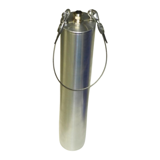
The core of this accelerometer is based on the same electronics used in AC-73 or AC-73i with the same performance. The housing for the AC-73-DH is made for insertion into a borehole with a diameter of 100 mm or higher. The orientation of the sensor in the hole can be defined either by the integrated compass (accessible over the iSensor interface) or by calculation using the azimuth of recorded known earthquakes and the borehole location. -
Page 12: Description
AC-73-DH will result in an electrical output proportional to the current used to keep the mass centred. This accelerometer output signal is calibrated to “g” gravity so that the current scale factor of the AC-73-DH is in units of milliamps per g. Because of the symmetrical positioning system incorporated with the force balance servo accelerometer principle, the accelerometer cannot arbitrarily change its scaling or drift out of calibration. -
Page 13: Sensor Physical Dimensions
User Manual & Installation Guide AC-73-DH Force Balance Accelerometer 13.04.2021 / V3. 13 / 20 4.3. Sensor physical dimensions +X = East +Y = North +Z = Up Figure 5. Sensor housing dimensions GS_AC-73-DH_UserManual+InstallationInstructions_V03.docx... -
Page 14: Sensor Interface
Table 3. AC-7x-DH Cable Wire Assignment and Colour Code When a GeoSIG connector is mounted at the cable end, the pin number is show in the first column. In case of a custom connector, please refer to the separate document which will be included with the sensor. -
Page 15: Isensor Interface
User Manual & Installation Guide AC-73-DH Force Balance Accelerometer 13.04.2021 / V3. 15 / 20 4.6. iSensor interface The AC-73-DH sensor is an intelligent sensor (iSensor) containing the following additional sensors to simplify the installation. Temperature sensor Humidity sensor ... -
Page 16: Installation Of The Software
User Manual & Installation Guide AC-73-DH Force Balance Accelerometer 16 / 20 13.04.2021 / V3. Computer Figure 7. Detailed cabling Make sure no shortcuts are made between all the other wires of the cable. 4.6.2. Installation of the Software To install the user interface, extract the content of the file iSensorUI.zip to any folder on your computer (e.g. -
Page 17: Figure 8. Csv File Opened In The Microsoft Excel
Temperature inside the AC-73-DH down-hole sensor in °C Relative humidity inside the AC-73-DH down-hole sensor in % TiltX: Tilt of the AC-73-DH sensor tube in direction of the X axis in ° TiltX: Tilt of the AC-73-DH sensor tube in direction of the Y axis in °... -
Page 18: Compass Calibration
13.04.2021 / V3. 4.6.4. Compass Calibration Compass calibration shall be done before the installation of the AC-73-DH sensor. Make sure that the sensor is powered and the setup is wired according to the Figure 6 and Figure 7. Then double-click on iSensor_Compass_Calibration.bat. - Page 19 User Manual & Installation Guide AC-73-DH Force Balance Accelerometer 13.04.2021 / V3. 19 / 20 Then the sensor sends the measurements as shown below to the screen. Time T(deg C) RH (%) TiltX(deg) TiltY(deg) MH,(deg) 2013/11/07 16:39:35 26.5 38.1 -0.5 203.0...
-
Page 20: Maintenance
The sensor should be opened for maintenance only by a qualified technician who has been trained by GeoSIG and has the required special tools. During the normal life of the sensor, there will be no need to open the sensor casing.
Need help?
Do you have a question about the AC-73-DH and is the answer not in the manual?
Questions and answers