
Subscribe to Our Youtube Channel
Related Manuals for GeoSIG AC-73


Summary of Contents for GeoSIG AC-73
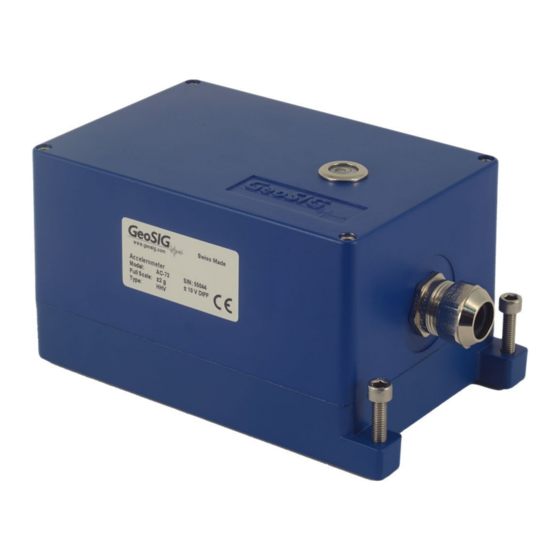
- Page 1 User Manual AC-73 Force Balance Accelerometer GeoSIG Ltd, Wiesenstrasse 39, 8952 Schlieren, Switzerland Phone: + 41 44 810 2150, Fax: + 41 44 810 2350 info@geosig.com, www.geosig.com...
- Page 2 Copyright Notice No part of this document may be reproduced without the prior written consent of GeoSIG Ltd. Software described in this document is furnished under a license and may only be used or copied in accordance with the terms of such a license.
- Page 3 User Manual AC-73 Force Balance Accelerometer 03.03.2023 / V9 3 / 7 Table of Contents Warnings and Safety ......................3 1. Basic specifications ......................4 2. Electrical Connector ......................4 2.1. Binder Serie 623 ............................. 4 2.2. Binder Serie 423 ............................. 5 2.3.
- Page 4 User Manual AC-73 Force Balance Accelerometer 4 / 7 03.03.2023 / V9 1. Basic specifications Sensor Series AC-7x Input range Acceleration, ±0.5, ±1.0, ±2.0, ±3.0 or ±4.0 g Output range 0 ± 10 Volt differential output (20 Vpp) Frequency range...
- Page 5 User Manual AC-73 Force Balance Accelerometer 03.03.2023 / V9 5 / 7 2.2. Binder Serie 423 P/N #J_CIR.012.010.M GeoSIG Binder Serie 423 P/N 99 5629 00 12 Figure 2, Binder Serie 423 connector The cable gland nut is determined according to external diameter of the cable and must be ordered separately.
- Page 6 User Manual AC-73 Force Balance Accelerometer 6 / 7 03.03.2023 / V9 3. Electric Configuration The full scale is field selectable without gain re-calibration by means of jumpers with fixed 0.1% precise amplifiers. 0.5 g Figure 3. Full scale selection for external AC-7x.
- Page 7 User Manual AC-73 Force Balance Accelerometer 03.03.2023 / V9 7 / 7 4. Mounting Small size and single bolt attachment allow the AC-7x to be easily installed, saving installation time. The integrated bubble level simplifies the levelling done by the three-point levelling screws.
Need help?
Do you have a question about the AC-73 and is the answer not in the manual?
Questions and answers