Sullair SD Series User Manual
Sd heatless desiccant compressed air dryers
Hide thumbs
Also See for SD Series:
- User manual (34 pages) ,
- User manual (44 pages) ,
- User manual (58 pages)

Related Manuals for Sullair SD Series


Summary of Contents for Sullair SD Series
- Page 1 ANUAL SERIES SD SD2000 – SD3400 DDS OPTION LDP OPTION 3V OPTION SD Heatless Desiccant Compressed Air Dryers...
-
Page 2: Table Of Contents
INSTALLATION, START-UP & MAINTENANCE MANUAL MODEL NO.: SD-2000 / SD-3400 REV 1 – October 29th,.2001 TABLE OF CONTENTS FOREWORD ..........................4 SECTION 1 INTRODUCTION....................5 1.1 GENERAL INFORMATION ....................5 1.2 SAFETY INSTRUCTIONS....................5 1.2.1 Identification of signs and symbols in this technical manual..........6 1.2.2 Safety tips for maintenance, inspection and assembly work.......... - Page 3 INSTALLATION, START-UP & MAINTENANCE MANUAL MODEL NO.: SD-2000 / SD-3400 REV 1 – October 29th,.2001 4.4.6 Accessories ........................ 26 SECTION 5 DRYER FLOW CAPACITY AND PURGE ADJUSTMENT ......27 5.1 DRYER FLOW CAPACITY ..................... 27 5.2 CORRECTION FACTOR FOR INLET TEMPERATURE..........27 5.3 PURGE ADJUSTMENT....................
-
Page 4: Foreword
REV 1 – October 29th,.2001 FOREWORD This technical manual of Sullair is an aid in getting to know the adsorption dryer better and in utilising its possibilities for application in accordance with its intended use. Furthermore, this manual contains important information for safe, proper and economic operation. -
Page 5: Section 1 Introduction
Sullair accepts no liability for corrosion damage and malfunctions caused by aggressive media. Applications other than those mentioned in this manual must be agreed to by Sullair and confirmed in writing. In the interest of further development, Sullair reserves the right to make changes at any... -
Page 6: Identification Of Signs And Symbols In This Technical Manual
INSTALLATION, START-UP & MAINTENANCE MANUAL MODEL NO.: SD-2000 / SD-3400 REV 1 – October 29th,.2001 SECTION 1 1.2.1 Identification of signs and symbols in this technical manual The safety tips contained in this technical manual, whose disregard could endanger people and machines, are indicated by a general danger sign and the additional markings Danger! or Attention! Danger! / Attention! Safety sign in accordance with DIN 4844 - W9... -
Page 7: Personnel Qualification
INSTALLATION, START-UP & MAINTENANCE MANUAL MODEL NO.: SD-2000 / SD-3400 REV 1 – October 29th,.2001 SECTION 1 Attention! − Never make structural changes to the adsorption dryer! − Only use original spare and accessory parts! − Never weld on a pressure vessel or change it in any way! Carry out maintenance work only when the adsorption dryer is switched off, is depressurized and disconnected... -
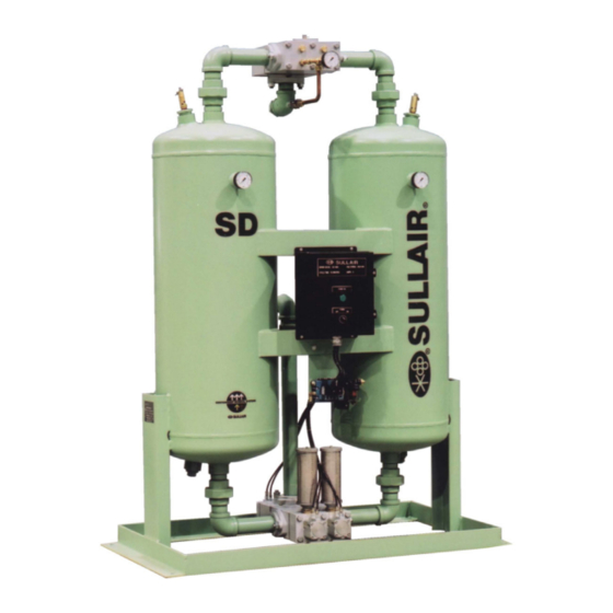
Page 8: Product Information
INSTALLATION, START-UP & MAINTENANCE MANUAL MODEL NO.: SD-2000 / SD-3400 REV 1 – October 29th,.2001 SECTION 1 PRODUCT INFORMATION The adsorption dryer is used for the purpose of drying compressed air and other gases according to its respective design. As a "standard model" the adsorption dryer is equipped with two desiccant vessels and a pre- and after-filter, and depending on certain conditions at the outlet, provides pure, dry and oil-free compressed air or gases. -
Page 9: Technical Data Sheet
INSTALLATION, START-UP & MAINTENANCE MANUAL MODEL NO.: SD-2000 / SD-3400 REV 1 – October 29th,.2001 SECTION 1 1.4.4 Technical data sheet Type SD2000 SD2350 SD2750 SD3400 Air, free of aggressive elements Medium Connection FLG – 150# 4” 4” 6” 6” Flow capacity (STD) 2000... - Page 10 INSTALLATION, START-UP & MAINTENANCE MANUAL MODEL NO.: SD-2000 / SD-3400 REV 1 – October 29th,.2001 Page 10...
-
Page 11: Transport
INSTALLATION, START-UP & MAINTENANCE MANUAL MODEL NO.: SD-2000 / SD-3400 REV 1 – October 29th,.2001 SECTION 1 1.4.5 Transport After the adsorption dryer has been delivered, it must be checked for damage that may have occurred during transport. If necessary, the Transport company must be informed to register the damage. -
Page 12: Section 2 Installation
Advice Should you still have questions regarding installation, you can request installation blueprints separately from Sullair. NOTE : On dryers size SD2750 and SD3400, the purge exhaust mufflers are not supplied. -
Page 13: Section 3 Start Up And Operation
DESCRIPTION OF THE OPERATION The Sullair adsorption dryer of the series SD2000 – SD3400 functions according to the pressure change principle, using dry air regeneration. Two adsorption vessels filled with desiccant are installed parallel to each other for this purpose. While the medium is being dried in one vessel, regeneration takes place in the other vessel. -
Page 14: Description Of The Operation
3.2.1 Description of the operation SD HEATLESS TYPE DRYER (SD2000-SD3400) • The Sullair SD dryer has a NEMA cycle time of 10 minutes (STD) or 4 minutes (LDP) depending upon the air quality desired. In a 10 minute cycle, 5 minutes is dedicated to drying for each chamber (5 minutes half cycle). -
Page 15: Dryer Operating Sequence (No Control Or Alarm Option)
3.2.2 Dryer operating sequence (No control or alarm option) The Sullair SD2000 –SD3400 heatless air dryers use a SIEMENS PLC as its standard controller. In the event of a power failure, the exhaust valves will close and the dryer will pressurize both chambers. - Page 16 INSTALLATION, START-UP & MAINTENANCE MANUAL MODEL NO.: SD-2000 / SD-3400 REV 1 – October 29th,.2001 SECTION 3 3.2.2 Dryer operating sequence (No control or alarm option) – (Continued) STEP 5 EFT CHAMBER DEPRESSURIZATION - Keep energized EV-1R - Energize Solenoid EV-2L opening left chamber depress valve. - At 30 PSIG falling pressure, energize EV-4L opening left chamber exhaust valve.
-
Page 17: Operating Sequence (Dds Option)
SECTION 3 3.2.3 Operating sequence (DDS Option) The Sullair SD2000-DDS – SD3400-DDS and all “LDP” heatless air dryer uses a Siemens PLC as its standard controller. In the event of a power failure, the exhaust valves will close and dryer will pressurize both chambers. Since this control panel uses retentive programming, the dryer will return to the same step in the cycle dryer was in before power was lost. - Page 18 INSTALLATION, START-UP & MAINTENANCE MANUAL MODEL NO.: SD-2000 / SD-3400 REV 1 – October 29th,.2001 SECTION 3 3.2.3 Operating sequence (DDS Option– (Continued) STEP 4 ELECT RIGHT CHAMBER DRYING - De-energize solenoid EV-1L - Energize solenoid EV-1R. - Inlet valve positioned for right chamber drying. - 3 seconds time delay, proceed to STEP 5 STEP 5 EFT CHAMBER DEPRESSURIZATION...
-
Page 19: Alarms
SECTION 3 3.2.3 Operating sequence (DDS Option– (Continued) NOTE 4: The regeneration and repressurization times should be adjusted by Sullair trained personnel only. Changing the factory settings will result in loss of dew point and/or failure to repressurize before changeover. -
Page 20: Electrical Control
You find the corresponding operating and control voltage on the data sheet. The Sullair adsorption dryer of the SD series is normally operated with a PLC controller. The set times are adjusted at the factory during the test run. Do not change these... -
Page 21: Dds Controls - Start Up And Operation
INSTALLATION, START-UP & MAINTENANCE MANUAL MODEL NO.: SD-2000 / SD-3400 REV 1 – October 29th,.2001 Digital display can be toggled to degrees F, C, and PPM. Detection for cable fault between hygrometer and moisture probe. Stainless steel humidity probe sampling cell with service valves. SECTION 3 3.3.2 DDS Controls –... -
Page 22: Section 4 Maintenance
MAINTENANCE Advice In order to ensure continuous and trouble-free operation, a maintenance contract with an authorized Sullair distributor is recommended. Also, the following points should be checked regularly: Daily • Carry out a general visual check and watch out for possible disturbances during operation. - Page 23 INSTALLATION, START-UP & MAINTENANCE MANUAL MODEL NO.: SD-2000 / SD-3400 REV 1 – October 29th,.2001 • Check the function of the 3-port inlet valve operation by sending electrical control signals. Page 23...
-
Page 24: Replacement Of The Desiccant
Advice Should the need for spare parts arise during work on the Sullair adsorption dryer of the SD2000 – SD3400 series, then the dryer type and the construction of the adsorption dryer must always be indicated. This information is given on the nameplate mounted on the electrical panel. -
Page 25: Filters
INSTALLATION, START-UP & MAINTENANCE MANUAL MODEL NO.: SD-2000 / SD-3400 REV 1 – October 29th,.2001 SECTION 4 FILTERS (OPTIONAL) 4.4.1 General comments and use Filters of the series PH/PR are suitable for filtering solids, oil and condensate out of compressed air and other neutral, compressed gases. This new filtration concept is characterized by high flows at low differential pressure. -
Page 26: Changing Of Filter Elements
INSTALLATION, START-UP & MAINTENANCE MANUAL MODEL NO.: SD-2000 / SD-3400 REV 1 – October 29th,.2001 SECTION 4 FILTERS (OPTIONAL) (Continued) 4.4.5 Changing of filter elements Danger! The soiled filter elements are changed only when the housings are DEPRESSURIZED! Filter elements are to be changed according to the following steps: •... -
Page 27: Section 5 Dryer Flow Capacity And Purge Adjustment
INSTALLATION, START-UP & MAINTENANCE MANUAL MODEL NO.: SD-2000 / SD-3400 REV 1 – October 29th,.2001 SECTION 5 DRYER FLOW CAPACITY AND PURGE ADJUSTMENT DRYER FLOW CAPACITY Model Selection Chart Max. Inlet Average Inlet Air Flow (SCFM) MODEL Air Pressure Based upon 100 F Inlet Air Temperature Inlet Air Pressure (Psig) SD 2000 1530... -
Page 28: Purge Adjustment
INSTALLATION, START-UP & MAINTENANCE MANUAL MODEL NO.: SD-2000 / SD-3400 REV 1 – October 29th,.2001 SECTION 5 DRYER FLOW CAPACITY AND PURGE ADJUSTMENT PURGE ADJUSTMENT To adjust the purge pressure, the following steps are to be followed, refer to the flow schematics at the end of this manual: The power is turned on, the dryer is operating. -
Page 29: Pressure Switch Adjustment
INSTALLATION, START-UP & MAINTENANCE MANUAL MODEL NO.: SD-2000 / SD-3400 REV 1 – October 29th,.2001 SECTION 5 PRESSURE SWITCH ADJUSTMENT Pressure switch adjustment for heatless dryers Adjustment knob On a SD dryer there are four (4) pressure switches (PSH-1, PSL-1, PSH-2 and PSL-2). The PSH pressure switches are set at 30 PSIG below the operating pressure of the dryer, and use the normally open contact. -
Page 30: Section 6 Spare Parts List
INSTALLATION, START-UP & MAINTENANCE MANUAL MODEL NO.: SD-2000 / SD-3400 REV 1 – October 29th,.2001 SECTION 6 SPARE PARTS LIST SD 2000 220002250130-195 KIT,RPR 3-PORT INL VLV ACT SD-1710-2350 1710-2350 02250130-190 GA,PRESS SD-220 - 3400 220-3400 02250130-191 SW,PRESS SD-220 - 3400 W/DDS 220-3400 02250130-193 CTL,PROGLOG SD-820 - 3400 W/O DDS... - Page 31 INSTALLATION, START-UP & MAINTENANCE MANUAL MODEL NO.: SD-2000 / SD-3400 REV 1 – October 29th,.2001 02250130-299 VLV,CHAMB RELIEF SD-2000 - 3400 2000-3400 02250130-251 SOL,DUAL SD-220 - 3400 220-3400 SECTION 6 SPARE PARTS LIST SD 2350 02250130-195 KIT,RPR 3-PORT INL VLV ACT SD-1710-2350 1710-2350 02250130-190 GA,PRESS SD-220 - 3400...
- Page 32 INSTALLATION, START-UP & MAINTENANCE MANUAL MODEL NO.: SD-2000 / SD-3400 REV 1 – October 29th,.2001 02250130-337 KIT,SPACER TEFLON 130-335 2000-2350 02250130-299 VLV,CHAMB RELIEF SD-2000 - 3400 2000-3400 02250130-251 SOL,DUAL SD-220 - 3400 220-3400 SECTION 6 SPARE PARTS LIST SD 2750 02250130-196 KIT,RPR 3-PORT INL VLV ACT SD-2750/3400 2750/3400...
- Page 33 INSTALLATION, START-UP & MAINTENANCE MANUAL MODEL NO.: SD-2000 / SD-3400 REV 1 – October 29th,.2001 Page 33...
- Page 34 INSTALLATION, START-UP & MAINTENANCE MANUAL MODEL NO.: SD-2000 / SD-3400 REV 1 – October 29th,.2001 SECTION 6 SPARE PARTS LIST SD 3400 02250130-196 KIT,RPR 3-PORT INL VLV ACT SD-2750/3400 2750/3400 02250130-190 GA,PRESS SD-220 - 3400 220-3400 02250130-191 SW,PRESS SD-220 - 3400 W/DDS 220-3400 02250130-193 CTL,PROGLOG SD-820 - 3400 W/O DDS...
-
Page 35: Service Bulletin
INSTALLATION, START-UP & MAINTENANCE MANUAL MODEL NO.: SD-2000 / SD-3400 REV 1 – October 29th,.2001 SECTION 6 SERVICE BULLETIN Vane Type Actuator Installation, Operation & Service Instructions Paddle postion indicator Shaft o-rings Bronze bushing Paddle o-ring Nylon bearings Paddle Stroke adjustment Vane type actuators are compact 90°... - Page 36 INSTALLATION, START-UP & MAINTENANCE MANUAL MODEL NO.: SD-2000 / SD-3400 REV 1 – October 29th,.2001 SECTION 6 SERVICE BULLETIN (Continued) 3. Utilize all mounting holes provided on the actuator and assure a full bolt diameter of thread engagement into the actuator housing as a minimum. 4.
- Page 37 INSTALLATION, START-UP & MAINTENANCE MANUAL MODEL NO.: SD-2000 / SD-3400 REV 1 – October 29th,.2001 WARNING ACTUATOR DAMAGE. The 90° stroke for the MX3000 must exceed two seconds to prevent actuator damage. SECTION 6 SERVICE BULLETIN (Continued) The 90° stroke for other Matryx models must exceed one second to prevent actuator damage.
- Page 38 INSTALLATION, START-UP & MAINTENANCE MANUAL MODEL NO.: SD-2000 / SD-3400 REV 1 – October 29th,.2001 SECTION 6 SERVICE BULLETIN (Continued) 5. Remove paddle and inspect bearing area for excessive wear. 6. Remove both stop adjusting screw assemblies (thread-seal, washer, locknut and stop adjusting screw).
- Page 39 INSTALLATION, START-UP & MAINTENANCE MANUAL MODEL NO.: SD-2000 / SD-3400 REV 1 – October 29th,.2001 to maintain seal integrity. 15. Using a wrench, rotate shaft from one side to the other several times manually to wipe sealant from joint. SECTION 6 SERVICE BULLETIN (Continued) 16.
- Page 40 INSTALLATION, START-UP & MAINTENANCE MANUAL MODEL NO.: SD-2000 / SD-3400 REV 1 – October 29th,.2001 SECTION 6 SERVICE BULLETIN (Continued) MAINTENANCE INSTRUCTIONS- SLEEVED PLUG VALVES Replacement parts. Replacement parts are designed for maximum interchangeability between valve sizes, types and models. However, some are not interchangeable; and, to ensure receiving correct parts, the following information must be supplied when ordering replacement parts.
- Page 41 INSTALLATION, START-UP & MAINTENANCE MANUAL MODEL NO.: SD-2000 / SD-3400 REV 1 – October 29th,.2001 SECTION 6 SERVICE BULLETIN (Continued) Adjustments. Loss of seal. All Tufline valves are factory adjusted and normally further adjustment is not required. However, if seepage does occur at the plug stem or downstream, the following adjustments can be made.
- Page 42 INSTALLATION, START-UP & MAINTENANCE MANUAL MODEL NO.: SD-2000 / SD-3400 REV 1 – October 29th,.2001 * Values at the plug can be greater **Torque at the input shaft less hand wheel or crank. SECTION 6 SERVICE BULLETIN (Continued) TOP SEAL REPLACEMENT INSTRUCTIONS WARNING !! WARNING !! MEDIA EXPOSURE.
- Page 43 INSTALLATION, START-UP & MAINTENANCE MANUAL MODEL NO.: SD-2000 / SD-3400 REV 1 – October 29th,.2001 SECTION 6 SERVICE BULLETIN (Continued) These surfaces should be free from defects, which are typically caused by corrosion, erosion, improper handling, or improper storage of a disassembled valve. If defects are found on any of these parts, the valve must not be repaired.
- Page 44 INSTALLATION, START-UP & MAINTENANCE MANUAL MODEL NO.: SD-2000 / SD-3400 REV 1 – October 29th,.2001 above the bottom of the valve body port opening. Do not apply force to the cover as this may damage the formed PTFE diaphragm. 29. Check to see that the metal diaphragm is centered in the valve body counterbore.
- Page 45 INSTALLATION, START-UP & MAINTENANCE MANUAL MODEL NO.: SD-2000 / SD-3400 REV 1 – October 29th,.2001 SECTION 6 SERVICE BULLETIN (Continued) REPAIR INSTRUCTIONS FOR 1 THROUGH 8 INCH VALVES, OUT-OF-LINE WARNING !! WARNING !! MEDIA EXPOSURE. Depressurize, MASSIVE LEAKAGE. DO NOT attempt to repair a clean, and neutralize any media that valve or its accessories while pressurized may remain in the valve and pipe-line.
- Page 46 INSTALLATION, START-UP & MAINTENANCE MANUAL MODEL NO.: SD-2000 / SD-3400 REV 1 – October 29th,.2001 SECTION 6 SERVICE BULLETIN (Continued) 3. After the sleeve has been cut, insert a screwdriver behind the sleeve and curl the sleeve away from the valve body. Remove the sleeve by prying it out of the body. Discard old sleeve.
- Page 47 INSTALLATION, START-UP & MAINTENANCE MANUAL MODEL NO.: SD-2000 / SD-3400 REV 1 – October 29th,.2001 lower ledge of the body and the top of the sleeve should be tucked under the upper ledge of the body. SECTION 6 SERVICE BULLETIN (Continued) 8.
- Page 48 INSTALLATION, START-UP & MAINTENANCE MANUAL MODEL NO.: SD-2000 / SD-3400 REV 1 – October 29th,.2001 assembly cone tool and onto plug stem. Check to see that the wedge ring has seated properly inside the crown of the formed PTFE diaphragm. Remove and discard assembly cone tool.
- Page 49 INSTALLATION, START-UP & MAINTENANCE MANUAL MODEL NO.: SD-2000 / SD-3400 REV 1 – October 29th,.2001 Replace hub (or E.G. actuator and bracket). Rotate the plug and compare the valve torque against the values listed under Running Torque on page 3. If satisfactory results have not been obtained, consult your nearest Tufline Service Center.
- Page 50 INSTALLATION, START-UP & MAINTENANCE MANUAL MODEL NO.: SD-2000 / SD-3400 REV 1 – October 29th,.2001 SECTION 6 SERVICE BULLETIN (Continued) CHECK VALVE Bushing Seat o’ring Bushing Guide Spring Page 50...
- Page 51 INSTALLATION, START-UP & MAINTENANCE MANUAL MODEL NO.: SD-2000 / SD-3400 REV 1 – October 29th,.2001 SECTION 6 SERVICE BULLETIN (Continued) EPRESS EXHAUST VALVE Valve actuator Valve body Valve body gasket Valve seat disk Page 51...
-
Page 52: Section 7 Trouble Shooting & Faults
INSTALLATION, START-UP & MAINTENANCE MANUAL MODEL NO.: SD-2000 / SD-3400 REV 1 – October 29th,.2001 SECTION 7 TROUBLE SHOOTING & FAULTS THE DEW POINT IS TOO HIGH Possible cause Solution ⇒ Operating pressure too low, air flow capacity too Increase operating pressure, reduce air flow high capacity •... -
Page 53: Back Pressure Is Too High During Regeneration Phase
Pilot air pressure failed due to plugged pilot filter or damaged pilot line. Attention! If you are not able to fix a problem, contact your local Sullair distributor or call Sullair SHORT-TERM SHUT-DOWN Advices The following sequence is to be heeded when switching off the adsorption dryer: •... -
Page 54: Shut-Down In Case Of A Fault Or For Maintenance
INSTALLATION, START-UP & MAINTENANCE MANUAL MODEL NO.: SD-2000 / SD-3400 REV 1 – October 29th,.2001 SECTION 7 SHUT-DOWN IN CASE OF A FAULT OR FOR MAINTENANCE Danger! Before any kind of maintenance or repair work is done, the adsorption dryer must be depressurized and disconnected from the power source. - Page 55 Tel (33) 4-77-96-84-70 Fax: 755-685 3473 Fax(33) 4-77-96-84-99 SULLAIR CORPORATION Subsidiary of Sundstrand Corporation 3700 East Michigan Boulevard Michigan City, Indiana 46360 – U.S.A Tel: 1-800-SULLAIR (USA only) or 1-(219)-879-5451 Fax: 1 (219)-874-1273 Fax Parts: (219) 874-1835 / Fax Service: (219) 874-1805...
Need help?
Do you have a question about the SD Series and is the answer not in the manual?
Questions and answers