Sullair SD Series User Manual
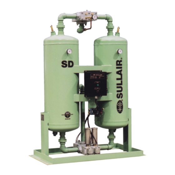
Heatless desiccant compressed air dryer
Hide thumbs
Also See for SD Series:
- User manual (44 pages) ,
- User manual (56 pages) ,
- User manual (58 pages)

Related Manuals for Sullair SD Series


Summary of Contents for Sullair SD Series
- Page 1 User Manual SD Series SD-220 to SD-600 3V OPTION SD Heatless Desiccant Compressed Air Dryer Serial Numbers 0001 to 8795 Ref: 02250130-735...
-
Page 2: Table Of Contents
INSTALLATION, START-UP & MAINTENANCE MANUAL SD-220 TO SD-600 REV 04 – 10 Oct 2003 TABLE OF CONTENTS SECTION 1: INTRODUCTION ..................4 1.1. GENERAL INFORMATION .................. 4 1.2. SAFETY INSTRUCTIONS..................4 1.2.1. Identification of Signs and Symbols in this Technical Manual ...... 5 1.2.2. - Page 3 INSTALLATION, START-UP & MAINTENANCE MANUAL SD-220 TO SD-600 REV 04 – 10 Oct 2003 SECTION 5: DRYER FLOW CAPACITY AND PURGE ADJUSTMENT ...... 22 5.1. DRYER FLOW CAPACITY................. 22 5.2. CORRECTION FACTOR FOR INLET TEMPERATURE ........22 5.3. PURGE ADJUSTMENT..................23 SECTION 6: SPARE PARTS LISTS ................
- Page 4 REV 04 – 10 Oct 2003 FOREWORD This Sullair technical manual is intended to help you get to know the SD adsorption dryer and to understand how to utilise its possibilities for application in accordance with its intended use. Furthermore, this manual contains important information for safe, proper and economic operation.
-
Page 5: Section 1: Introduction
Sullair accepts no liability for corrosion damage and malfunctions caused by aggressive media. Applications other than those mentioned in this manual must be agreed to by Sullair and confirmed in writing. In the interest of further development, Sullair reserves the right to make changes at any... -
Page 6: Identification Of Signs And Symbols In This Technical Manual
INSTALLATION, START-UP & MAINTENANCE MANUAL SD-220 TO SD-600 REV 04 – 10 Oct 2003 1.2.1. Identification of Signs and Symbols in this Technical Manual The safety tips contained in this technical manual, whose disregard could endanger people and property, are indicated by a general danger sign and the additional markings Danger! or Attention! Danger! / Caution! Safety sign in accordance with DIN 4844 - W9... -
Page 7: Personnel Qualification
CAUTION! • Never make structural changes to the adsorption dryer! • Only use original Sullair spares and accessory parts! • Never weld on a pressure vessel or change it in any way! • Carry out maintenance work only when the adsorption dryer is switched off, is depressurized and disconnected from the electric power supply. -
Page 8: Product Information
INSTALLATION, START-UP & MAINTENANCE MANUAL SD-220 TO SD-600 REV 04 – 10 Oct 2003 1.4. PRODUCT INFORMATION The adsorption dryer is used for the purpose of drying compressed air and other gases according to its respective design. As a "standard model" the adsorption dryer is equipped with two desiccant vessels, a pre filter and an after filter, and depending on certain conditions at the outlet, provides pure, dry and oil-free compressed air or gas. -
Page 9: Technical Data Sheet
* EDP (Enhanced Dew Point) Option indicates a dryer which has been specifically set up at the factory to obtain a –100 F pressure dewpoint. This option requires deration of the rated flow. Contact Sullair for details. Page 8 of 32... -
Page 10: Transport
In order to prevent droplets of condensate, oil, or dirt from getting into the desiccant, a Sullair MPH pre-filter must be installed up stream of the adsorption dryer. Without proper pre-filtration an oil film will build up on the desiccant reducing it’s drying capacity and degrading performance. -
Page 11: Section 2: Installation
☛ Note Should you still have questions regarding installation, you can request additional installation recommendations from Sullair. CAUTION! Do not hydrotest the dryer! All vessel assemblies are factory pressure tested per design requirements prior to release from the manufacturer. -
Page 12: Section 3: Start Up And Operation
• All shut off valves on the pre-filter, adsorption dryer, after-filter and on the bypass line should be closed. • The ambient temperature must not be less than 33°F Breakdowns resulting from faulty installation do not fall under Sullair’s warranty obligation. ☛ Note The following sequence is to be heeded for the initial start-up: •... -
Page 13: Description Of The Operation
3.2.1. Description of the Operation • The standard Sullair SD dryer operates on a 10 minute NEMA cycle. In this configuration each desiccant chamber is drying for 5 minutes. This is known as a 5 minute half cycle. (EDP Dryers operate on a 4 minute NEMA cycle or 2 minute half cycle). -
Page 14: Dryer Operating Sequence
REV 04 – 10 Oct 2003 3.2.2. Dryer Operating Sequence The Sullair SD-220-DDS to SD-600-DDS heatless air dryers use a PLC as the standard controller. In the event of a power failure, the inlet valves remain in their position, and the exhaust valves will close and dryer will pressurize both chambers. -
Page 15: Electrical Control
You will find the operating and control voltage on the data sheet. The Sullair SD-220 to SD-600 adsorption dryers are normally operated with a PLC controller. The set times are adjusted at the factory during the test run. -
Page 16: Section 4: Maintenance
SECTION 4: MAINTENANCE ☛ Note - In order to ensure continuous and trouble-free operation, a maintenance contract with an authorized Sullair distributor is recommended. The following points should be checked regularly: Daily • Carry out a general visual check and watch out for possible disruptions during operation. -
Page 17: Replacement Of The Desiccant
INSTALLATION, START-UP & MAINTENANCE MANUAL SD-220 TO SD-600 REV 04 – 10 Oct 2003 Annually or after every 2500 hours of operation • Check the desiccant for impurities and change it if necessary. A brown or yellow color indicates that it has been contaminated with oil. Desiccant has an operating lifetime of about 8000 hours under normal conditions. -
Page 18: Changing Of The Regeneration Orifice
☛ Note Use only original Sullair spare parts when working on the Sullair SD-220 to SD- 600 series dryers. The dryer type, model and serial number are required to ensure correct parts are supplied. This information can be found on the nameplate mounted on the control panel. -
Page 19: Technical Documents
INSTALLATION, START-UP & MAINTENANCE MANUAL SD-220 TO SD-600 REV 04 – 10 Oct 2003 4.4. TECHNICAL DOCUMENTS INLET – PURGE EXHAUST MANIFOLD For SD-220 through SD-600 Page 18 of 32... - Page 20 INSTALLATION, START-UP & MAINTENANCE MANUAL SD-220 TO SD-600 REV 04 – 10 Oct 2003 TECHNICAL DOCUMENTS (Continued) OUTLET CHECK VALVE MANIFOLD For SD-220through SD-600 Page 19 of 32...
-
Page 21: Filters
FILTERS 4.5.1. General Comments and Use Sullair MPH high efficiency pre-filters and MPR reverse flow after filters are designed to remove solids, oil and water condensate out of compressed air and other neutral, compressed gases. These filters provide high flows and low differential pressures. -
Page 22: Changing Of Filter Elements
INSTALLATION, START-UP & MAINTENANCE MANUAL SD-220 TO SD-600 REV 04 – 10 Oct 2003 4.5.5. Changing of Filter Elements DANGER! The filter housings must be depressurized completely before attempting to replace filter elements. CAUTION! The elements can be disposal of at a suitable disposal site in accordance with local regulations. -
Page 23: Section 5: Dryer Flow Capacity And Purge Adjustment
INSTALLATION, START-UP & MAINTENANCE MANUAL SD-220 TO SD-600 REV 04 – 10 Oct 2003 SECTION 5: DRYER FLOW CAPACITY & PURGE ADJUSTMENT 5.1. DRYER FLOW CAPACITY Model Selection Chart Rated inlet air flow (scfm) at given pressures (psig) (Based upon 100 F inlet air temperature) MODEL SD-220... -
Page 24: Purge Adjustment
INSTALLATION, START-UP & MAINTENANCE MANUAL SD-220 TO SD-600 REV 04 – 10 Oct 2003 CORRECTION FACTOR FOR INLET TEMPERATURE (Continued) Example: To size for an inlet flow of 570 SCFM @ 105 F and 110 Psig. Select a model that produces at least 570 SCFM at 110 psig. This case would be the SD-600 which can dry 700 SCFM. -
Page 25: Section 6: Spare Parts Lists
INSTALLATION, START-UP & MAINTENANCE MANUAL SD-220 TO SD-600 REV 04 – 10 Oct 2003 SECTION 6: SPARE PARTS LISTS 6.1. SPARE PARTS LIST FOR SD-220 TO SD-400 Part Number DESCRIPTION SD-220 SD-300 SD-400 PRESSURE GAUGE 02250130-190 02250130-190 02250130-190 PRESSURE SWITCH 02250130-191 02250130-191 02250130-191... - Page 26 INSTALLATION, START-UP & MAINTENANCE MANUAL SD-220 TO SD-600 REV 04 – 10 Oct 2003 SPARE PARTS LIST FOR SD-220 TO SD-400 (Continued) INLET CYLINDER KIT 02250096-552 02250096-552 02250096-552 INLET CYLINDER SEAL KIT 02250096-551 02250096-551 02250096-551 INLET PLATE KIT 02250119-586 02250119-586 02250119-586 INLET VALVE HOUSING BOLT KIT 02250096-533...
- Page 27 INSTALLATION, START-UP & MAINTENANCE MANUAL SD-220 TO SD-600 REV 04 – 10 Oct 2003 6.2. SPARE PARTS LIST FOR SD-500 & SD-600 Part Number DESCRIPTION SD-500 SD-600 PRESSURE GAUGE 02250130-190 02250130-190 PRESSURE SWITCH 02250130-191 02250130-191 PROGRAMABLE LOGIC CONTROLLER (NON-DDS) 02250130-192 02250130-192 LIGHT BULB 02250130-203...
-
Page 28: Spare Parts List For Sd-500 & Sd-600
INSTALLATION, START-UP & MAINTENANCE MANUAL SD-220 TO SD-600 REV 04 – 10 Oct 2003 SPARE PARTS LIST FOR SD-500 & SD-600 (Continued) INLET STRIKE PLATE KIT 02250096-540 02250096-540 INLET VALVE KIT 02250119-585 02250119-585 INLET/EXHAUST VALVE FLANGE O-RING KIT 02250096-591 02250096-591 KADDIS DRAIN 02250096-590 02250096-590... -
Page 29: Inlet-Exhaust Valve Manifold
INSTALLATION, START-UP & MAINTENANCE MANUAL SD-220 TO SD-600 REV 04 – 10 Oct 2003 6.3. INLET-EXHAUST VALVE MANIFOLD Page 28 of 32... -
Page 30: Outlet Check Valve Manifold
INSTALLATION, START-UP & MAINTENANCE MANUAL SD-220 TO SD-600 REV 04 – 10 Oct 2003 6.4. OUTLET-CHECK VALVE MANIFOLD Page 29 of 32... -
Page 31: Section 7: Trouble Shooting & Faults
INSTALLATION, START-UP & MAINTENANCE MANUAL SD-220 TO SD-600 REV 04 – 10 Oct 2003 SECTION 7: TROUBLE SHOOTING & FAULTS 7.1. THE DEW POINT IS TOO HIGH Possible Cause Solution Operating pressure too low, air flow capacity too high Increase operating pressure, reduce air flow capacity Air inlet temperature too high Reduce temperature, or connect an air cooler upstream Differential pressure at the pre-filter too high... -
Page 32: Back Pressure Is Too High During Regeneration Phase
Check valves are not sealing Repair check valve CAUTION! If you are not able to fix a problem, call your local Sullair distributor or the Sullair Service Department. A service technician will help you with the problem or, if necessary, be sent to site. -
Page 33: Shut-Down In Case Of A Fault Or For Maintenance
INSTALLATION, START-UP & MAINTENANCE MANUAL SD-220 TO SD-600 REV 04 – 10 Oct 2003 7.5. SHUT-DOWN IN CASE OF A FAULT OR FOR MAINTENANCE DANGER! Before any kind of maintenance or repair work is done, the adsorption dryer must be depressurized and disconnected from the power source. Apply general safety procedures. - Page 34 Fax(33) 4-77-96-84-99 Fax: 755-685 3473 SULLAIR CORPORATION Subsidiary of Sundstrand Corporation 3700 East Michigan Boulevard, Michigan City, Indiana 46360 – U.S.A Toll Free (USA only): 1-800-SULLAIR Outside the USA: 1-(219)-879-5451 Fax: 1 (219)-874-1273 Fax Parts: (219) 874-1835 Fax Service: (219) 874-1805...
Need help?
Do you have a question about the SD Series and is the answer not in the manual?
Questions and answers