Table of Contents
Advertisement
USER/SERVICE MANUAL
RC S
ERIES
REFRIGERATED CYCLING COMPRESSED AIR DRYER
150-3000 CFM
PART NUMBER:
02250195-402 R01
KEEP FOR
FUTURE
WARRANTY NOTICE
REFERENCE
SULLAIR CORPORATION
©
Failure to follow the instructions
The information in this manual is current
and procedures in this manual or,
as of its publication date, and applies to
misuse of this equipement will
compressor serial number:
VOID its warranty!
0711SA0250
and all subsequent serial numbers.
Advertisement
Table of Contents

Related Manuals for Sullair RC Series


Summary of Contents for Sullair RC Series
- Page 1 PART NUMBER: 02250195-402 R01 KEEP FOR FUTURE WARRANTY NOTICE REFERENCE SULLAIR CORPORATION © Failure to follow the instructions The information in this manual is current and procedures in this manual or, as of its publication date, and applies to misuse of this equipement will...
- Page 2 AIR CARE SEMINAR TRAINING Sullair Air Care Seminars are courses that provide hands-on instruction for the proper operation, maintenance, and servicing of Sullair products. Individual seminars on Industrial compressors and compressor electrical systems are offered at regular intervals throughout the year at Sullair’s corporate headquarters training facility located at Michigan City, Indiana.
-
Page 3: Table Of Contents
TABLE OF CONTENTS SECTION 1—SAFETY INSTRUCTIONS SAFETY REGULATIONS: ISSUES TO AVOID RECEIVING AND INSPECTION TRANSPORTATION INSTALLATION LAYOUT REQUIREMENTS ENVIRONMENTAL PROTECTION SECTION 2—INTRODUCTION SECTION 3—SPECIFICATIONS PRODUCT PICTURE / PRODUCT FINAL ASSEMBLY DRAWING PRODUCT MODELS AND SPECIFICATIONS SECTION 4—PRODUCT DESCRIPTION PRODUCT FEATURES SECTION 5—PRINCIPLE OF OPERATION REFRIGERATION HEAT EXCHANGER COMPRESSED AIR HEAT EXCHANGER... - Page 4 TABLE OF CONTENTS 5.15 ED—RC 700 5.16 ED—RC 700 WATER COOLED 5.17 ED—RC 850 AIR COOLED 5.18 ED—RC 850 WATER COOLED 5.19 ED—RC 1000 AIR COOLED 5.20 ED—RC 1000 WATER COOLED 5.21 ED—RC 1200 AIR COOLED 5.22 ED—RC 1200 WATER COOLED 5.23 ED—RC 1600 AIR COOLED 5.24...
- Page 5 TABLE OF CONTENTS 5.55 WIRING DIAGRAM—RC 250-400 (230/3 60 AC) 5.56 WIRING DIAGRAM—RC 250-400 (400/460/575/3 50/60 AC) 5.57 WIRING DIAGRAM—RC 250-400 (400/460/575/3 50/60 AC) 5.58 WIRING DIAGRAM—RC (500-1000) 230/60 AC 5.59 WIRING DIAGRAM—RC (500-1000) 230/60 AC 5.60 WIRING DIAGRAM—RC 500-3000 (400/460/575/3 50/60 AC) 5.61 WIRING DIAGRAM—RC 500-3000 (400/460/575/3 50/60 AC) 5.62...
- Page 6 TABLE OF CONTENTS...
-
Page 7: Safety Instructions
INSPECTION 3. The user is responsible for safe operating conditions. Parts and accessories must be Sullair dryers are factory tested prior to shipment. replaced if inspection shows that it is unsafe However, during shipment, there are chances that to operate the dryer. - Page 8 NOTES TRANSPORTATION heat radiated by the dryer. (About 18 watts for each SCFM under ISO 7183-5 condition 1. Use care and caution when transporting the or 40 watt for each liter/sec under ISO 7183- dryer. Avoid sudden jerks, tilting, dropping A condition).
- Page 9 Sullair’s cycling refrigerated air dryers to freezing and a host of other problems that will provide dry air at full load continuously. diminish the life of your entire compressed air system. With a Sullair refrigerant dryer, you can be...
- Page 10 NOTES...
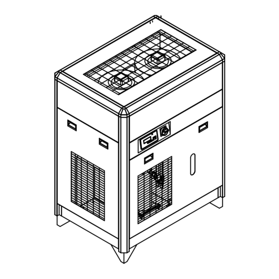
- Page 11 40 Deg. F Maximum Operating Temperature 150 Deg. F If your application does not match the above criteria, contact your Sullair distributor and they will be able to provide the right dryer for your application. PRODUCT PICTURE / PRODUCT FINAL ASSEMBLY DRAWING...
- Page 12 NOTES PRODUCT MODELS AND SPECIFICATIONS Cycling 02250193-793 DRYER, RC150CFM, 115/1/60-AC RC-0150-115-1-60-A 115/1/60 Cycling 02250193-864 DRYER, RC150CFM, 220/1/50-AC RC-0150-220-1-50-A 220/1/50 Cycling 02250193-820 DRYER, RC150CFM, 208-230/1/60-AC RC-0150-230-1-60-A 208-230/1/60 Cycling 02250193-865 DRYER, RC175CFM, 220/1/50-AC RC-0175-220-1-50-A 220/1/50 Cycling 02250193-821 DRYER, RC175CFM, 208-230/1/60-AC RC-0175-230-1-60-A 208-230/1/60 Cycling 02250193-866 DRYER, RC200CFM, 220/1/50-AC...
- Page 13 SECTION 3 SPECIFICATIONS Cycling 02250193-968 DRYER, RC850CFM, 460/3/60-AC RC-0850-460-3-60-A 460/3/60 Cycling 02250193-999 DRYER, RC850CFM, 460/3/60-WC RC-0850-460-3-60-W 460/3/60 Cycling 02250194-126 DRYER, RC850CFM, 575/3/60-AC RC-0850-575-3-60-A 575/3/60 Cycling 02250194-153 DRYER, RC850CFM, 575/3/60-WC RC-0850-575-3-60-W 575/3/60 Cycling 02250193-829 DRYER, RC1000CFM, 230/3/60-AC RC-1000-230-3-60-A 230/3/60 Cycling 02250193-859 DRYER, RC1000CFM, 230/3/60-WC RC-1000-230-3-60-W 230/3/60...
- Page 14 NOTES...
-
Page 15: Product Description
PRODUCT DESCRIPTION Section 4 PRODUCT DESCRIPTION 4.1.3 This refrigerated compressed air dryer has been EFRIGERANT CIRCUIT PROTECTION designed to remove water vapor from industrial 1. Overload protector: compressed air that is free of any aggressive Single phase compressors are equipped contaminants like ammonia, gaseous acid, dust, rust, with an overload protector which is a current/ liquid condensate, any other chemical or mineral... - Page 16 PRODUCT DESCRIPTION SECTION 4 4.1.6 4.1.8 EFRIGERANT CIRCUIT REGULATION IN EAT EXCHANGER MODULAR DESIGN RC-0150 – RC-3000 The dryers are equipped with compact, modular design heat exchangers. This assembly has been 1. The liquid refrigerant is injected into the specially designed to dry compressed air and evaporator through a metering device trying consists of: to maintain the refrigerant in the evaporator...
- Page 17 SECTION 4 PRODUCT DESCRIPTION The fourth parameter is SEtH (Set point; high glycol ROCEDURE TO CHANGE THE CONTROLLER FROM temperature). SEtH will display quickly on then the ENTIGRADE TO AHRENHEIT current parameter value will be displayed. Use the The controller is password protected. Press the Enter arrow to change this value to 36 (36◦F).
- Page 18 NOTES...
-
Page 19: Refrigeration Heat Exchanger
PRINCIPLE OF OPERATION Section 5 PRINCIPLE OF OPERATION The refrigerant circuit can be divided in 3 parts: glycol solution. It is pumped continuously through the heat exchangers to eliminate 1. Low pressure section with an evaporator any dew point fluctuations commonly found (heat exchanger) in other cycling dryers. -
Page 20: Compressed Air Heat Exchanger
PRINCIPLE OF OPERATION SECTION 5 dust and dirt accumulation on the condenser 2. Pre-separation: As the air is pre-cooled, coils. Air temperature should not exceed some of the moisture condenses. During this 110ºF(43ºC). A clearance of 24 inches (61 phase, all condensed moisture and oil is separated from the compressed air. -
Page 21: Typical Installation Diagram
SECTION 5 PRINCIPLE OF OPERATION TYPICAL INSTALLATION DIAGRAM PIPE/CONNECTION OPERATING PRECAUTIONS REQUIREMENTS Refer Section 3.2: Product Models WARNING Specifications. Verify that the operating parameters match ELECTRICAL CONNECTION with the nominal values stated on the data REQUIREMENTS nameplate of the dryer (voltage, frequency, air pressure, air temperature, ambient tem- The owner shall furnish all labor, materials, perature, etc.). -
Page 22: Installation
If you are in doubt, contact compressed air flow. your Sullair distributor. It is recommended to use the same pipe size as that of the dryer Inlet and Outlet. -
Page 23: Operating Procedures
7. Reassemble valve and test, using the test outlet valve closed (3 valve bypass is option button on the electronic drain timer panel. offered by Sullair). 12. Push the green on switch. The 'dryer on' light will illuminate and 8. Repressurize system and test drain by using... -
Page 24: Ed-Rc
ED—RC 175 02250195-243... -
Page 25: Ed-Rc
ED—RC 175 PART NUMBER DESCRIPTION PART NUMBER DESCRIPTION M-CMP-0200-230-1-60-A COMPRESSOR M-HP2-0200 CABINET HORIZONTAL PROFILE 2 M-CON-0175 CONDENSER M-CTC-3000 CABINET TOP CORNER M-FMT-0200-230-1-50 FAN MOTOR M-CPS-3000 CABINET HANDLE M-FAN-0200 FAN BLADE M-STU-3000 CABINET STUD AND NUT M-GRL-0200 FAN GRILL M-FAS-3000 CABINET FASTENER M-DRI-0200 DRIER-DEHYDRATOR M-NUT-3000... - Page 26 5.10 ED—RC 200 02250195-243...
-
Page 27: Ed-Rc
5.10 ED—RC 200 PART NUMBER DESCRIPTION PART NUMBER DESCRIPTION M-CMP-0200-230-1-60-A COMPRESSOR M-CTC-3000 CABINET TOP CORNER M-CON-0175 CONDENSER M-CPS-3000 CABINET HANDLE M-FMT-0200-230-1-60 FAN MOTOR M-STU-3000 CABINET STUD AND NUT M-FAN-0200 FAN BLADE M-FAS-3000 CABINET FASTENER M-GRL-0200 FAN GRILL M-NUT-3000 CAGE NUT AND SCREW M-DRI-0200 DRIER-DEHYDRATOR M-SCR-3000... - Page 28 5.11 ED—RC 250 02250195-244...
-
Page 29: Ed-Rc
5.11 ED—RC 250 PART NO. DESCRIPTIONS PART NO. DESCRIPTIONS SEE REF. TABLE COMPRESSOR M-CRI-0400-C CABINET SIDE-RIGHT M-CON-0325 CONDENSER M-CRE-0400-C CABINET REAR SEE REF. TABLE FAN MOTOR M-CTO-0400-C CABINET TOP M-DRI-1000 DRIER-DEHYDRATOR M-CBA-0400-C CABINET BASE M-EXC-0125 HEAT EXCHANGER M-CBL-0400-C CABINET LEG M-WHC-0400 EVAPORATOR (WATER HEAT EXCHANGER) M-HP1-0400-C... -
Page 30: Ed-Rc
5.12 ED—RC 325 02250195-244... - Page 31 5.12 ED—RC 325 PART NUMBER DESCRIPTION PART NUMBER DESCRIPTION SEE REF. TABLE COMPRESSOR M-CLE-0400-C CABINET SIDE-LEFT M-CON-0325 CONDENSER M-CRI-0400-C CABINET SIDE-RIGHT SEE REF. TABLE FAN MOTOR M-CRE-0400-C CABINET REAR M-DRI-1000 DRIER-DEHYDRATOR M-CTO-0400-C CABINET TOP M-EXC-0200 HEAT EXCHANGER M-CBA-0400-C CABINET BASE M-WHC-0400 EVAPORATOR (WATER HEAT EXCHANGER) M-CBL-0400-C...
- Page 32 5.13 ED—RC 400 02250195-244...
- Page 33 5.13 ED—RC 400 PART NUMBER DESCRIPTION PART NUMBER DESCRIPTION SEE REF. TABLE COMPRESSOR M-CLE-0400-C CABINET SIDE-LEFT M-CON-0400 CONDENSER M-CRI-0400-C CABINET SIDE-RIGHT SEE REF. TABLE FAN MOTOR M-CRE-0400-C CABINET REAR M-DRI-1000 DRIER-DEHYDRATOR M-CTO-0400-C CABINET TOP M-EXC-0200 HEAT EXCHANGER M-CBA-0400-C CABINET BASE M-WHC-0400 EVAPORATOR (WATER HEAT EXCHANGER) M-CBL-0400-C...
- Page 34 5.14 ED—RC 500 02250195-245...
- Page 35 5.14 ED—RC 500 PART NUMBER DESCRIPTION PART NUMBER DESCRIPTION SEE REF. TABLE COMPRESSOR M-CSD-0850-C CABINET SIDE M-CON-0500 CONDENSER M-CRE-0500-C CABINET REAR SEE REF. TABLE FAN MOTOR M-CTO-0700-C CABINET TOP M-DRI-1000 DRIER-DEHYDRATOR M-CBA-0850C CABINET BASE M-EXC-0200 HEAT EXCHANGER M-CBL-0850-C CABINET LEG M-WHC-0500 EVAPORATOR (WATER HEAT EXCHANGER) M-HP1-0850-C...
-
Page 36: Ed—Rc 700
5.15 ED—RC 700 02250195-245... - Page 37 5.15 ED—RC 700 PART NUMBER DESCRIPTION PART NUMBER DESCRIPTION SEE REF. TABLE COMPRESSOR M-CSD-0850-C CABINET SIDE M-CON-0700 CONDENSER M-CRE-0850-C CABINET REAR SEE REF. TABLE FAN MOTOR M-CTO-0850-C CABINET TOP M-DRI-1000 DRIER-DEHYDRATOR M-CBA-0850-C CABINET BASE M-EXC-0200 HEAT EXCHANGER M-CBL-0850-C CABINET LEG M-WHC-1000 EVAPORATOR (WATER HEAT EXCHANGER) M-HP1-0850-C...
-
Page 38: Ed-Rc 700 Water Cooled
5.16 ED—RC 700 WATER COOLED 02250196-554... - Page 39 5.16 ED—RC 700 WATER COOLED PART NUMBER DESCRIPTION PART NUMBER DESCRIPTION SEE REF. TABLE COMPRESSOR M-CSD-0850-C CABINET SIDE M-CON-0700-W CONDENSER M-CRE-0700-C CABINET REAR M-DRI-1200 DRIER-DEHYDRATOR M-CTO-0700-C CABINET TOP M-EXC-0200 HEAT EXCHANGER M-CBA-0850-C CABINET BASE EVAPORATOR (WATER HEAT M-CBL-0-850-C CABINET LEG M-WHC-1000 EXCHANGER) M-HP1-0850-C...
-
Page 40: Ed-Rc 850 Air Cooled
5.17 ED—RC 850 AIR COOLED 02250196-553... - Page 41 5.17 ED—RC 850 AIR COOLED PART NUMBER DESCRIPTION PART NUMBER DESCRIPTION SEE REF. TABLE COMPRESSOR M-CSD-0850-C CABINET SIDE M-CON-850 CONDENSER M-CRE-0850-C CABINET REAR SEE REF. TABLE FAN MOTOR M-CTO-0850-C CABINET TOP M-DRI-1200 DRIER-DEHYDRATOR M-CBA-0850-C CABINET BASE M-EXC-0200 HEAT EXCHANGER M-CBL-0850-C CABINET LEG EVAPORATOR (WATER HEAT M-HP1-0850-C...
-
Page 42: Ed-Rc 850 Water Cooled
5.18 ED—RC 850 WATER COOLED 02250196-556... - Page 43 5.18 ED—RC 850 WATER COOLED PART NUMBER DESCRIPTION PART NUMBER DESCRIPTION SEE REF. TABLE COMPRESSOR M-CSD-0850-C CABINET SIDE M-CON-850W CONDENSER M-CRE-0850-C CABINET REAR M-DRI-1200 DRIER-DEHYDRATOR M-CTO-0850-C CABINET TOP M-EXC-0200 HEAT EXCHANGER M-CBA-0850-C CABINET BASE EVAPORATOR (WATER HEAT M-CBL-0850-C CABINET LEG M-WHC-1000 EXCHANGER) M-HP1-0850-C...
-
Page 44: Ed-Rc 1000 Air Cooled
5.19 ED—RC 1000 AIR COOLED 02250196-557... - Page 45 5.19 ED—RC 1000 AIR COOLED PART NUMBER DESCRIPTION PART NUMBER DESCRIPTION SEE REF. TABLE COMPRESSOR M-CSD-1000-C CABINET SIDE M-CON-850 CONDENSER M-CRE-1000-C CABINET REAR SEE REF. TABLE FAN MOTOR M-CTO-1000-C CABINET TOP M-DRI-1200 DRIER-DEHYDRATOR M-CBA-1000-C CABINET BASE M-EXC-0200 HEAT EXCHANGER M-CBL-1200-C CABINET LEG EVAPORATOR (WATER HEAT M-HP1-1000-C...
-
Page 46: Ed-Rc 1000 Water Cooled
5.20 ED—RC 1000 WATER COOLED 02250196-558... - Page 47 5.20 ED—RC 1000 WATER COOLED PART NUMBER DESCRIPTION PART NUMBER DESCRIPTION M-CMP-1000-460-3-60 COMPRESSOR M-CSD-1000-C CABINET SIDE M-CON-850 CONDENSER M-CRE-1000-C CABINET REAR M-DRI-1200 DRIER-DEHYDRATOR M-CTO-1000-CW CABINET TOP M-EXC-1000 HEAT EXCHANGER M-CBA-1000-C CABINET BASE EVAPORATOR (WATER HEAT M-CBL-1200 CABINET LEG M-WHC-1000 EXCHANGER) M-HP1-1200 CABINET HORIZONTAL PROFILE 1 M-EXV-1000...
-
Page 48: Ed-Rc 1200 Air Cooled
5.21 ED—RC 1200 AIR COOLED 02250196-559... - Page 49 5.21 ED—RC 1200 AIR COOLED PART NUMBER DESCRIPTION PART NUMBER DESCRIPTION SEE REF. TABLE COMPRESSOR M-CSD-1200-C CABINET SIDE M-CON-850 CONDENSER M-CRE-1200-C CABINET REAR SEE REF. TABLE FAN MOTOR M-CTO-1200-C CABINET TOP M-DRI-1200 DRIER-DEHYDRATOR M-CBA-1200-C CABINET BASE M-EXC-1200 HEAT EXCHANGER M-CBL-1200-C CABINET LEG EVAPORATOR (WATER HEAT M-HP1-1200-C...
-
Page 50: Ed-Rc 1200 Water Cooled
5.22 ED—RC 1200 WATER COOLED 02250196-560... - Page 51 5.22 ED—RC 1200 WATER COOLED PART NUMBER DESCRIPTION PART NUMBER DESCRIPTION M-CMP-1600-460-3-60-A COMPRESSOR M-CSD-1200-C CABINET SIDE M-CON-1200-W CONDENSER M-CRE-1200-C CABINET REAR M-DRI-1200 DRIER-DEHYDRATOR M-CTO-1200-CW CABINET TOP M-EXC-1200 HEAT EXCHANGER M-CBA-1200-C CABINET BASE EVAPORATOR (WATER HEAT M-CBL-1200 CABINET LEG M-WHC-1200 EXCHANGER) M-HP1-1200-C CABINET HORIZONTAL PROFILE 1 M-EXV-1250...
-
Page 52: Ed-Rc 1600 Air Cooled
5.23 ED—RC 1600 AIR COOLED 02250196-561... - Page 53 5.23 ED—RC 1600 AIR COOLED PART NUMBER DESCRIPTION PART NUMBER DESCRIPTION M-CMP-1200-460-3-60-A COMPRESSOR M-CSD-2000-C CABINET SIDE M-CON-1600 CONDENSER M-CRE-2000-C CABINET REAR M-FMT-1600-460-3-60 FAN MOTOR M-CTO-2000-C CABINET TOP M-DRI-2400 DRIER-DEHYDRATOR M-CBA-2000-C CABINET BASE M-EXC-2000 HEAT EXCHANGER M-CBL-6000-C CABINET LEG EVAPORATOR (WATER HEAT M-HP1-2000-C CABINET HORIZONTAL PROFILE 1 M-WHC-1000...
-
Page 54: Ed-Rc 1600 Water Cooled
5.24 ED—RC 1600 WATER COOLED 02250196-562... - Page 55 5.24 ED—RC 1600 WATER COOLED PART NUMBER DESCRIPTION PART NUMBER DESCRIPTION M-CMP-1200-460-3-60-A COMPRESSOR M-CSD-2000-C CABINET SIDE M-CON-1600W CONDENSER M-CRE-2000-C CABINET REAR M-DRI-2400 DRIER-DEHYDRATOR M-CTO-2000-CW CABINET TOP M-EXC-2000 HEAT EXCHANGER M-CBA-2000-C CABINET BASE EVAPORATOR (WATER HEAT M-CBL-6000-C CABINET LEG M-WHC-1600 EXCHANGER) M-HP1-2000-C CABINET HORIZONTAL PROFILE 1 M-EXV-2000...
-
Page 56: Ed-Rc 2000 Air Cooled
5.25 ED—RC 2000 AIR COOLED 02250196-563... - Page 57 5.25 ED—RC 2000 AIR COOLED PART NUMBER DESCRIPTION PART NUMBER DESCRIPTION M-CMP-2000-460-3-60-A COMPRESSOR M-CSD-2000-C CABINET SIDE M-CON-2400 CONDENSER M-CRE-2000-C CABINET REAR M-FMT-460-3-60 FAN MOTOR M-CTO-2000-C CABINET TOP M-DRI-2400 DRIER-DEHYDRATOR M-CBA-2000-C CABINET BASE M-EXC-2000 HEAT EXCHANGER M-CBL-6000-C CABINET LEG EVAPORATOR (WATER HEAT M-HP1-2000-C CABINET HORIZONTAL PROFILE 1 M-WHC-2000...
-
Page 58: Ed-Rc 2000 Water Cooled
5.26 ED—RC 2000 WATER COOLED 02250196-564... - Page 59 5.26 ED—RC 2000 WATER COOLED PART NUMBER DESCRIPTION PART NUMBER DESCRIPTION M-CMP-2000-460-3-60-A COMPRESSOR M-CSD-2000-C CABINET SIDE M-CON-2000-w CONDENSER M-CRE-2000-C CABINET REAR M-DRI-2400 DRIER-DEHYDRATOR M-CTO-2000-C CABINET TOP M-EXC-2000 HEAT EXCHANGER M-CBA-2000-C CABINET BASE EVAPORATOR (WATER HEAT M-CBL-6000-C CABINET LEG M-WHC-2000 EXCHANGER) M-HP1-2000-C CABINET HORIZONTAL PROFILE 1 M-EXV-2000...
-
Page 60: Ed-Rc 2400 Air Cooled
5.27 ED—RC 2400 AIR COOLED 02250196-565... - Page 61 5.27 ED—RC 2400 AIR COOLED PART NUMBER DESCRIPTION PART NUMBER DESCRIPTION M-CSD-3000-C CABINET SIDE M-CMP-2400-460-3-60-A COMPRESSOR M-CRE-3000-C CABINET REAR M-CON-2400 CONDENSER M-CTO-0300-C CABINET TOP M-FMT-2000-460-3-60 FAN MOTOR M-CBA-3000-C CABINET BASE M-DRI-2400 DRIER-DEHYDRATOR M-CBL-6000-C CABINET LEG M-EXC-0200 HEAT EXCHANGER M-HP1-3000-C CABINET HORIZONTAL PROFILE 1 EVAPORATOR (WATER HEAT M-WHC-2400 EXCHANGER)
-
Page 62: Ed-Rc 2400 Water Cooled
5.28 ED—RC 2400 WATER COOLED 02250196-567... - Page 63 5.28 ED—RC 2400 WATER COOLED PART NUMBER DESCRIPTION PART NUMBER DESCRIPTION M-CMP-2400-460-3-60-A COMPRESSOR M-CSD-3000-C CABINET SIDE M-CON-2400 CONDENSER M-CRE-3000-C CABINET REAR M-DRI-2400 DRIER-DEHYDRATOR M-CTO-0300-CW CABINET TOP M-EXC-2400 HEAT EXCHANGER M-CBA-3000-C CABINET BASE EVAPORATOR (WATER HEAT M-CBL-6000 CABINET LEG M-WHC-2400 EXCHANGER) M-HP1-3000-C CABINET HORIZONTAL PROFILE 1 M-EXV-2400...
-
Page 64: Ed-Rc 3000 Air Cooled
5.29 ED—RC 3000 AIR COOLED 02250196-568... - Page 65 5.29 ED—RC 3000 AIR COOLED PART NUMBER DESCRIPTION PART NUMBER DESCRIPTION M-CMP-3000-460-3-60-A COMPRESSOR M-CSD-3000-C CABINET SIDE M-CON-3000 CONDENSER M-CRE-3000-C CABINET REAR M-FMT-2000-460-3-60 FAN MOTOR M-CTO-3000-C CABINET TOP M-DRI-1200 DRIER-DEHYDRATOR M-CBA-3000-C CABINET BASE M-EXC-3000 HEAT EXCHANGER M-CBL-3000-C CABINET LEG EVAPORATOR (WATER HEAT M-HP1-3000-C CABINET HORIZONTAL PROFILE 1 M-WHC-1000...
-
Page 66: Ed-Rc 3000 Water Cooled
5.30 ED—RC 3000 WATER COOLED 02250196-569... - Page 67 5.30 ED—RC 3000 WATER COOLED PART NUMBER DESCRIPTION PART NUMBER DESCRIPTION M-CMP-3000-460-3-60-A COMPRESSOR M-CRE-3000-C CABINET REAR M-CON-3000 CONDENSER M-CTO-3000-CW CABINET TOP M-DRI-2400 DRIER-DEHYDRATOR M-CBA-3000-C CABINET BASE M-EXC-3000 HEAT EXCHANGER M-CBL-6000 CABINET LEG EVAPORATOR (WATER HEATER M-HP1-3000-C CABINET HORIZONTAL PROFILE 1 M-WHC-3000 EXCHANGER) M-HP2-3000-C...
-
Page 68: P&I-Rc150-850
5.31 P&I—RC150-850 02250195-273... - Page 69 THERMO. EXP. VALVE SUCTION ACCUMULATOR LOW PRESSURE ISOLATION VALVE HIGH PRESSURE SAFETY VALVE RECEIVER REFRIG. FILTER DRIER AIR VENT FLOAT SWITCH COLD STORAGE TANK SIGHT GLASS AIR FILTER OPTIONAL WATER PUMP WATER PRESSURE SWITCH NOTE: MARK/TAG COMPONENT/CONTAINER WITH SULLAIR P/N AND REVISION.
-
Page 70: P&I-Rc400-850
5.32 P&I—RC400-850 02250195-279... - Page 71 EVAPORATOR THERMO. EXP. VALVE SUCTION ACCUMULATOR LOW PRESSURE ISOLATION VALVE HIGH PRESSURE SAFETY VALVE RECEIVER REFRIG. FILTER DRIER AIR VENT FLOAT SWITCH COLD STORAGE TANK SIGHT GLASS WATER PUMP WATER PRESSURE SWITCH NOTE: MARK/TAG COMPONENT/CONTAINER WITH SULLAIR P/N AND REVISION.
-
Page 72: P&I-Rc1000-3000
5.33 P&I—RC1000-3000 02250195-281... - Page 73 THERMO. EXP. VALVE SUCTION ACCUMULATOR LOW PRESSURE ISOLATION VALVE HIGH PRESSURE SAFETY VALVE RECEIVER REFRIG. FILTER DRIER AIR VENT FLOAT SWITCH COLD STORAGE TANK SIGHT GLASS AIR FILTER OPTIONAL WATER PUMP WATER PRESSURE SWITCH NOTE: MARK/TAG COMPONENT/CONTAINER WITH SULLAIR P/N AND REVISION.
-
Page 74: P&I-Rc1000-3000
5.34 P&I—RC1000-3000 02250195-283... -
Page 75: P&I-Rc1000-3000
THERMO. EXP. VALVE RC2400 SUCTION ACCUMULATOR LOW PRESSURE RC3000 ISOLATION VALVE HIGH PRESSURE SAFETY VALVE RECEIVER REFRIG. FILTER DRIER AIR VENT FLOAT SWITCH COLD STORAGE TANK SIGHT GLASS WATER PUMP WATER PRESSURE SWITCH NOTE: MARK/TAG COMPONENT/CONTAINER WITH SULLAIR P/N AND REVISION. -
Page 76: Id-Rc
5.36 ID—RC 175-200 02250195-243... - Page 77 5.36 ID—RC 175-200 DRYER PART POWER RATINGS COOLING DECAL NUMBER 02250193-793 115V/1Ph/60Hz AIR COOLED RC150 02250193-864 220V/1Ph/50Hz AIR COOLED RC150 02250193-820 208-230V/1Ph/60Hz AIR COOLED RC150 02250193-865 220V/1Ph/50Hz AIR COOLED RC175 02250193-821 208-230V/1Ph/60Hz AIR COOLED RC175 02250193-866 220V/1Ph/50Hz AIR COOLED RC200 02250193-822 208-230V/1Ph/60Hz AIR COOLED...
-
Page 78: Id—Rc 250-400
5.37 ID—RC 250-400 02250195-244... -
Page 79: Id-Rc
5.37 ID—RC 250-400 DRYER PART POWER RATINGS COOLING DECAL NUMBER 02250193-867 220V/1Ph/50Hz AIR COOLED RC250 02250193-823 230V/3Ph/60Hz AIR COOLED RC250 02250193-904 400V/3Ph/50Hz AIR COOLED RC250 02250193-963 460V/3Ph/60Hz AIR COOLED RC250 02250194-121 575V/3Ph/60Hz AIR COOLED RC250 02250193-824 230V/3Ph/60Hz AIR COOLED RC325 02250193-905 400V/3Ph/50Hz AIR COOLED... - Page 80 5.38 ID—RC 500-850 02250195-245...
- Page 81 5.38 RC 500-850 DRYER PART POWER RATINGS COOLING DECAL NUMBER 02250193-826 230V/3Ph/60Hz AIR COOLED RC500 02250193-907 400V/3Ph/50Hz AIR COOLED RC500 02250193-966 460V/3Ph/60Hz AIR COOLED RC500 02250194-124 575V/3Ph/60Hz AIR COOLED RC500 02250193-827 230V/3Ph/60Hz AIR COOLED RC700 02250193-908 400V/3Ph/50Hz AIR COOLED RC700 02250193-966 460V/3Ph/60Hz AIR COOLED...
-
Page 82: Id-Rc 1000-1200 Air Cooled
5.39 ID—RC 1000-1200 AIR COOLED 02250195-246... -
Page 83: Id-Rc 1000-1200 Water Cooled
5.40 ID—RC 1000-1200 WATER COOLED 02250195-246... -
Page 84: Id-Rc 1600-2000 Air Cooled
5.41 ID—RC 1600-2000 AIR COOLED 02250195-248... -
Page 85: Id-Rc 1600-2000 Water Cooled
5.42 ID—RC 1600-2000 WATER COOLED 02250195-248... -
Page 86: Id-Rc 2400-3000 Air Cooled
5.43 ID—RC 2400-3000 AIR COOLED 02250195-249... -
Page 87: Id-Rc 2400-3000 Water Cooled
5.44 ID—RC 2400-3000 WATER COOLED 02250195-249... -
Page 88: Wiring Diagram—Control Circuit Rc 150 (110/120-1-50/60-A
5.45 WIRING DIAGRAM—CONTROL CIRCUIT RC 150 (110/120-1-50/60-A, 208/230-1-50/60-A) 02250195-313-1... -
Page 89: Wiring Diagram-Control Circuit Rc
5.45 WIRING DIAGRAM—CONTROL CIRCUIT RC 150 (110/120-1-50/60-A, 208/230-1-50/60-A) A01: CONTROL CIRCUIT TRANSFORMER A10-1: RUNNING LAMP ON CONTROL PANEL (GREEN) A10-2: REMOTE CONTROL RUNNING LAMP (GREEN) A10-3: DUAL BUTTON CONTROL LAMP (GREEN) A11-1: STAND-BY LAMP ON CONTROL PANEL (RED) A11-2: REMOTE CONTROL STAND-BY LAMP (RED) A20: DRAIN VALVE K01:... - Page 90 5.46 WIRING DIAGRAM—POWER CIRCUIT RC 150 (110/120-1-50/60-A, 208/230-1-50/60-A) 02250195-313-2...
- Page 91 5.46 WIRING DIAGRAM—POWER CIRCUIT RC 150 (110/120-1-50/60-A, 208/230-1-50/60-A) RUN WINDING START WINDING MOTOR PROTECTION A01: CONTROL CIRCUIT TRANSFORMER B01: MAIN TERMINAL BLOCK A01 PRIMARY PROTECTION K01: COMPRESSOR CONTACTOR K10: FAN CONTACTOR K40: WATER MOTOR M01: COMPRESSOR M10: FAN MOTOR M40: WATER MOTOR S01: MAIN SWITCH...
- Page 92 5.47 WIRING DIAGRAM—CONTROL CIRCUIT RC 200 (208/230-1-50/60-A) 02250195-315-1...
-
Page 93: Wiring Diagram-Control Circuit Rc 200 (208/230-1-50/60-A)
5.47 WIRING DIAGRAM—CONTROL CIRCUIT RC 200 (208/230-1-50/60-A) A01: CONTROL CIRCUIT TRANSFORMER A10-1: RUNNING LAMP ON CONTROL PANEL (GREEN) A10-2: REMOTE CONTROL RUNNING LAMP (GREEN) A10-3: DUAL BUTTON CONTROL LAMP (GREEN) A11-1: STAND-BY LAMP ON CONTROL PANEL (RED) A11-2: REMOTE CONTROL STAND-BY LAMP (RED) A20: DRAIN VALVE K01:... -
Page 94: Wiring Diagram—Power Circuit Rc 200 (208/230-1-50/60-A
5.48 WIRING DIAGRAM—POWER CIRCUIT RC 200 (208/230-1-50/60-A) 02250195-315-2... - Page 95 5.48 WIRING DIAGRAM—POWER CIRCUIT RC 200 (208/230-1-50/60-A) RUN WINDING START WINDING MOTOR PROTECTION A01: CONTROL CIRCUIT TRANSFORMER B01: MAIN TERMINAL BLOCK A01 PRIMARY PROTECTION K01: COMPRESSOR CONTACTOR K10: FAN CONTACTOR K40: WATER MOTOR M01: COMPRESSOR M10: FAN MOTOR M40: WATER MOTOR S01: MAIN SWITCH FAN MOTOR (BROWN)
- Page 96 5.49 WIRING DIAGRAM—CONTROL CIRCUIT RC 250 (208/230-1-50/60-A) 02250195-316-1...
-
Page 97: Wiring Diagram-Control Circuit Rc 250 (208/230-1-50/60-A)
5.49 WIRING DIAGRAM—CONTROL CIRCUIT RC 250 (208/230-1-50/60-A) A01: CONTROL CIRCUIT TRANSFORMER A10-1: RUNNING LAMP ON CONTROL PANEL (GREEN) A10-2: REMOTE CONTROL RUNNING LAMP (GREEN) A10-3: DUAL BUTTON CONTROL LAMP (GREEN) A11-1: STAND-BY LAMP ON CONTROL PANEL (RED) A11-2: REMOTE CONTROL STAND-BY LAMP (RED) A20: DRAIN VALVE K01:... -
Page 98: Wiring Diagram—Power Circuit Rc 250 (208/230-1-50/60-A
5.50 WIRING DIAGRAM—POWER CIRCUIT RC 250 (208/230-1-50/60-A) 02250195-316-2... - Page 99 5.50 WIRING DIAGRAM—POWER CIRCUIT RC 250 (208/230-1-50/60-A) RUN WINDING START WINDING MOTOR PROTECTION A01: CONTROL CIRCUIT TRANSFORMER A30: COMPRESSOR CHANKASER HEATER B01: MAIN TERMINAL BLOCK A01 PRIMARY PROTECTION K01: COMPRESSOR CONTACTOR K10: FAN CONTACTOR K40: WATER MOTOR M01: COMPRESSOR M10: FAN MOTOR M40: WATER MOTOR...
-
Page 100: Wiring Diagram—Control Circuit Rc 250/3000 (230-3-50/60-A
5.51 WIRING DIAGRAM—CONTROL CIRCUIT RC 250/3000 (230-3-50/60-A, 400/460-3-50/60-A) 02250195-317-1... - Page 101 5.51 WIRING DIAGRAM—CONTROL CIRCUIT RC 250/3000 (230-3-50/60-A, 400/460-3-50/60-A) A01: CONTROL CIRCUIT TRANSFORMER S10-2: FAN PRESSURE CONTROL 2 A10-1: RUNNING LAMP ON CONTROL PANEL (GREEN) S11: HP-LP SECURITY CONTROL A10-2: REMOTE CONTROL RUNNING LAMP (GREEN) S20: SECURITY THERMOSTAT A10-3: DUAL BUTTON CONTROL LAMP (GREEN) S30-1: FAN PROTECTOR I A11-1:...
- Page 102 5.52 WIRING DIAGRAM—POWER CIRCUIT RC 250/3000 (230-3-50/60-A, 400/460-3-50/60-A) 02250195-317-2...
-
Page 103: Wiring Diagram-Power Circuit Rc 250/3000
5.52 WIRING DIAGRAM—POWER CIRCUIT RC 250/3000 (230-3-50/60-A, 400/460-3-50/60-A) A01-1: CONTROL CIRCUIT TRANSFORMER A30-1/A30-2: COMPRESSOR CHANKASER HEATERS B01: MAIN TERMINAL BLOCK EMR4: PHASE PROTECTION RELAY F1,F2: A01 PRIMARY PROTECTION K01: COMPRESSOR CONTACTOR (24V) K10-1: FAN CONTACTOR1 (24V) K10-2: FAN CONTACTOR2 (24V) K40: WATER MOTOR M01-1/M01-2:... -
Page 104: Wiring Diagram-Rc 150-250 (115/220/1 50/60 Ac)
5.53 WIRING DIAGRAM—RC 150-250 (115/220/1 50/60 AC) 02250195-299... - Page 105 5.53 WIRING DIAGRAM—RC 150-250 (115/220/1 50/60 AC) Compressor overload protection Control circuit protector Electronic drain supply Timer relay Economizer relay Compressor motor relay Water motor relay Compressor starting relay Main switch Fan pressure switch High pressure switch Water low pressure switch Compressor motor Fan motor Water motor...
-
Page 106: Wiring Diagram-Rc 250-400 (230/3 60 Ac)
5.54 WIRING DIAGRAM—RC 250-400 (230/3 60 AC) 02250195-300-1... - Page 107 5.54 WIRING DIAGRAM—RC 250-400 (230/3 60 AC) control circuit transformer compressor chankaser heaters main terminal block control circuit supply EMR4 phase protection relay F1, F2, F3 EMR4 overload protection A01 primary protection A30 overload protection A01 secondary protection compressor contactor fan contactor water motor contactor compressors...
-
Page 108: Wiring Diagram—Rc 250-400 (230/3 60 Ac
5.55 WIRING DIAGRAM—RC 250-400 (230/3 60 AC) 02250195-300-2... - Page 109 5.55 WIRING DIAGRAM—RC 250-400 (230/3 60 AC) control circuit protection timer relay economizer protection thermostatic sensor (PT100) compressor motor relay indicates high pressure water motor relay indicates low pressure fan motor relay indicates high temperature in the circuit economizer relay thermal protection of compressor thermal protection of water motor thermal protector of fan...
-
Page 110: Wiring Diagram—Rc 250-400 (400/460/575/3 50/60 Ac
5.56 WIRING DIAGRAM—RC 250-400 (400/460/575/3 50/60 AC) 02250195-969-1... - Page 111 5.56 WIRING DIAGRAM—RC 250-400 (400/460/575/3 50/60 AC) control circuit transformer compressor chankaser heaters main terminal block control circuit supply EMR4 phase protection relay F1, F2, F3 EMR4 overload protection A01 primary protection A30 overload protection A01 secondary protection compressor contactor fan contactor water motor contactor compressors...
-
Page 112: Wiring Diagram—Rc 250-400 (400/460/575/3 50/60 Ac
5.57 WIRING DIAGRAM—RC 250-400 (400/460/575/3 50/60 AC) 02250195-969-2... - Page 113 5.57 WIRING DIAGRAM—RC 250-400 (400/460/575/3 50/60 AC) control circuit protection timer relay economizer protection thermostatic sensor (PT100) compressor motor relay indicates high pressure water motor relay indicates low pressure fan motor relay indicates high temperature in the circuit economizer relay thermal protection of compressor thermal protection of water motor thermal protector of fan...
-
Page 114: Wiring Diagram-Rc (500-1000) 230/60 Ac
5.58 WIRING DIAGRAM— RC (500-1000) 230/60 AC 02250195-168-1... -
Page 115: Wiring Diagram-Rc (500-1000) 230/60 Ac
5.58 WIRING DIAGRAM— RC (500-1000) 230/60 AC control circuit transformer compressor chankaser heaters main terminal block control circuit supply EMR4 phase protection relay F1, F2, F3 EMR4 overload protection A01 primary protection A30 overload protection A01 secondary protection compressor contactor K10-1 fan contactor K10-2... -
Page 116: Wiring Diagram—Rc (500-1000) 230/60 Ac
5.59 WIRING DIAGRAM— RC (500-1000) 230/60 AC 02250195-3168-2... - Page 117 5.59 WIRING DIAGRAM— RC (500/700/850/1000/1200/1600/2000/2400/3000) 460-3-60-A, 400-3-60-A control circuit protection drain timer supply economizer protection EMR4 phase protection relay compressor motor relay alarm contact water motor relay timer relay K10-1 fan motor relay thermostatic sensor (PT100) K10-2 fan motor relay indicates high pressure economizer relay indicates low pressure...
-
Page 118: Wiring Diagram—Rc 500-3000 (400/460/575/3 50/60 Ac
5.60 WIRING DIAGRAM—RC 500-3000 (400/460/575/3 50/60 AC) 02250195-301-1... - Page 119 5.60 WIRING DIAGRAM—RC 500-3000 (400/460/575/3 50/60 AC) control circuit transformer compressor chankaser heaters main terminal block control circuit supply EMR4 phase protection relay F1, F2, F3 EMR4 overload protection A01 primary protection A30 overload protection A01 secondary protection compressor contactor water motor contactor K10-1 fan contactor...
-
Page 120: Wiring Diagram—Rc 500-3000 (400/460/575/3 50/60 Ac
5.61 WIRING DIAGRAM—RC 500-3000 (400/460/575/3 50/60 AC) 02250195-301-2... - Page 121 5.61 WIRING DIAGRAM—RC 500-3000 (400/460/575/3 50/60 AC) control circuit protection A11-2 remote control stand-by lamp (red) economizer protection drain timer supply compressor motor relay EMR4 phase protection relay water motor relay alarm contact K10-1 fan motor relay timer relay K10-2 fan motor relay thermostatic sensor (PT100) economizer relay...
-
Page 122: Wiring Diagram—Rc 700-3000 (400/460/575/3 50/60 Ac
5.62 WIRING DIAGRAM—RC 700-3000 (400/460/575/3 50/60 AC) 02250195-971-1... - Page 123 5.62 WIRING DIAGRAM—RC 700-3000 (400/460/575/3 50/60 AC) control circuit transformer compressor chankaser heaters main terminal block control circuit supply EMR4 phase protection relay F1, F2, F3 EMR4 overload protection A01 primary protection A30 overload protection A01 secondary protection compressor contactor water motor contactor compressors water motor...
-
Page 124: Wiring Diagram—Rc Rc 700-3000 (400/460/575/3 50/60 Ac
5.63 WIRING DIAGRAM—RC RC 700-3000 (400/460/575/3 50/60 AC) 02250195-971-2... - Page 125 5.63 WIRING DIAGRAM—RC 700-3000 (400/460/575/3 50/60 AC) control circuit protection indicates high pressure economizer protection indicates low pressure compressor motor relay indiates high temperature in the circuit water motor relay economizer relay thermal protection of compressor thermal protection of water motor S02-1 start button on control panel S02-2...
-
Page 126: How To Change Water / Gylicol Temperature Set Point
PRINCIPLE OF OPERATION SECTION 5 5.64 HOW TO CHANGE WATER / GYLICOL TEMPERATURE SET POINT: using arrows change setting. Press buttons at the same time. Factory setting for is 25 F is seen on the screen. Factory set code is Press and see By using... -
Page 127: Section 6-Maintenance
MAINTENANCE Section 6 MAINTENANCE MAINTENANCE BY AN MAINTENANCE BY THE ENGINEER/TECHNICIAN USER 1. Maintenance and repairs should only be 1. Keep the dryer clean. performed when the air dryer is shut down 2. In case of more than 4 pounds of refriger- depressurized and when the main... -
Page 128: Recommended Maintenance
MAINTENANCE SECTION 6 RECOMMENDED MAINTENANCE Table 6-1: Recommended Maintenance Semi- Recommended Maintenance Activity Weekly Monthly Annual Annual Air Condenser Cleaning Water condenser cleaning Replacement of Filter Element Refrigerant Gas Leak (for dryers containing more then 4 lb of gas) Refrigerant Gas Leak (for dryers containing more then 66 lb of gas) Drain control Cleaning drain strainer inside drain ball valve... - Page 129 NOTES...
-
Page 130: Replacement Parts
REPLACEMENT PARTS Component Name RC-0150-115-1-60-A RC-0150-220-1-50-A RC-0150-230-1-60-A RC-0175-220-1-50-A RC-0175-230-1-60-A Refrigerant Gas R134a R134a R134a R134a R134a compressor M-CMP-0150-115-1-60-A M-CMP-0200-220-1-50-A M-CMP-0200-230-1-60-A M-CMP-0200-230-1-60-A M-CMP-0200-230-1-60-A compressor electric box Condenser M-CON-0175 M-CON-0175 M-CON-0175 M-CON-0175 M-CON-0175 Fan motor M-FMT-0150-115-1-60 M-FMT-0200-220-1-50 M-FMT-0200-230-1-50 M-FMT-0200-220-1-50 M-FMT-0200-230-1-50 Fan Blade M-FAN-0200 M-FAN-0200 M-FAN-0200... - Page 131 Component Name RC-0150-115-1-60-A RC-0150-220-1-50-A RC-0150-230-1-60-A RC-0175-220-1-50-A RC-0175-230-1-60-A On/off Button M-ONB-0200 M-ONB-0200 M-ONB-0200 M-ONB-0200 M-ONB-0200 Main Switch M-MNS-0700 M-MNS-0700 M-MNS-0700 M-MNS-0700 M-MNS-0700 Contactor M-CNT-400 M-CNT-400 M-CNT-400 M-CNT-400 M-CNT-400 Phase protection relay Fan Contactor Transformer Secondary contact M-SEC-1000 M-SEC-1000 M-SEC-1000 M-SEC-1000 M-SEC-1000 Timer M-TMR-3000 M-TMR-3000...
- Page 132 Component Name RC-0200-220-1-50-A RC-0200-230-1-60-A RC-0250-220-1-50-A RC-0250-230-3-60-A RC-0250-400-3-50-A Refrigerant Gas R134a R134a R134a R134a R134a compressor M-CMP-0200-220-1-50-A M-CMP-0200-230-1-60-A M-CMP-250-220-1-50-A M-CMP-250-230-3-60-A M-CMP-250-460-3-60-A compressor electric box Condenser M-CON-0175 M-CON-0175 M-CON-0325 M-CON-0325 M-CON-0325 Fan motor M-FMT-0200-230-1-50 M-FMT-0200-230-1-60 M-FMT-0325-220-1-50 M-FMT-0700-460-3-60 M-FMT-0700-460-3-50 Fan Blade M-FAN-0200 M-FAN-0200 fan grill M-GRL-0200 M-GRL-0200...
- Page 133 Component Name RC-0200-220-1-50-A RC-0200-230-1-60-A RC-0250-220-1-50-A RC-0250-230-3-60-A RC-0250-400-3-50-A Main Switch M-MNS-0700 M-MNS-0700 M-MNS-0700 M-MNS-0700 M-MNS-0700 Contactor M-CNT-400 M-CNT-400 M-CNT-400 M-CNT-400 M-CNT-400 Phase protection relay M-PPR-1000 M-PPR-1000 Fan Contactor M-FCN-1000 M-FCN-1000 Transformer M-TRF-1000 M-TRF-1000 Secondary contact M-SEC-1000 M-SEC-1000 M-SEC-1000 M-SEC-1000 M-SEC-1000 Timer M-TMR-3000 M-TMR-3000 M-TMR-3000...
- Page 134 Component Name RC-0250-460-3-60-A RC-0250-575-3-60-A RC-0325-230-3-60-A RC-0325-400-3-50-A RC-0325-460-3-60-A Refrigerant Gas R134a R134a R134a R134a R134a compressor M-CMP-250-460-3-60-A M-CMP-250-575-3-60-A M-CMP-325-230-3-60-A M-CMP-325-400-3-50-A M-CMP-325-460-3-60-A compressor electric box Condenser M-CON-0325 M-CON-0325 M-CON-0325 M-CON-0325 M-CON-0325 Fan motor M-FMT-0700-460-3-60 M-FMT-0700-575-3-60 M-FMT-0700-460-3-60 M-FMT-0700-460-3-50 M-FMT-1000-460-3-60 Fan Blade fan grill Drier-Dehydrator M-DRI-1000 M-DRI-1000...
- Page 135 Component Name RC-0250-460-3-60-A RC-0250-575-3-60-A RC-0325-230-3-60-A RC-0325-400-3-50-A RC-0325-460-3-60-A Main Switch M-MNS-0700 M-MNS-0700 M-MNS-0700 M-MNS-0700 M-MNS-0700 Contactor M-CNT-400 M-CNT-400 M-CNT-400 M-CNT-400 M-CNT-400 Phase protection relay M-PPR-1000 M-PPR-1000 M-PPR-1000 M-PPR-1000 M-PPR-1000 Fan Contactor M-FCN-1000 M-FCN-1000 M-FCN-1000 M-FCN-1000 M-FCN-1000 Transformer M-TRF-1000 M-TRF-1000 M-TRF-1000 M-TRF-1000 M-TRF-1000 Secondary contact M-SEC-1000...
- Page 136 Component Name RC-0400-230-3-60-A RC-0400-400-3-50-A RC-0400-460-3-60-A RC-0400-575-3-60-A RC-0500-230-3-60-A Refrigerant Gas R134a R134a R134a R134a R134a compressor M-CMP-400-230-3-60-A M-CMP-400-400-3-50-A M-CMP-400-460-3-60-A M-CMP-400-575-3-60-A M-CMP-500-230-3-60-A compressor electric box Condenser M-CON-0400 M-CON-0400 M-CON-0400 M-CON-0400 M-CON-0500 Fan motor M-FMT-0700-460-3-60 M-FMT-0700-460-3-50 M-FMT-0700-460-3-60 M-FMT-0700-575-3-60 M-FMT-0700-460-3-60 Fan Blade fan grill Drier-Dehydrator M-DRI-1000 M-DRI-1000...
- Page 137 Component Name RC-0400-230-3-60-A RC-0400-400-3-50-A RC-0400-460-3-60-A RC-0400-575-3-60-A RC-0500-230-3-60-A Main Switch M-MNS-0700 M-MNS-0700 M-MNS-0700 M-MNS-0700 M-MNS-0700 Contactor M-CNT-400 M-CNT-400 M-CNT-400 M-CNT-400 M-CNT-0850 Phase protection relay M-PPR-1000 M-PPR-1000 M-PPR-1000 M-PPR-1000 M-PPR-1000 Fan Contactor M-FCN-1000 M-FCN-1000 M-FCN-1000 M-FCN-1000 M-FCN-1000 Transformer M-TRF-1000 M-TRF-1000 M-TRF-1000 M-TRF-1000 M-TRF-1000 Secondary contact M-SEC-1000...
- Page 138 Component Name RC-0500-400-3-50-A RC-0500-460-3-60-A RC-0500-575-3-60-A RC-0700-230-3-60-A RC-0700-400-3-50-A Refrigerant Gas R134a R134a R134a R134a R134a compressor M-CMP-500-230-3-60-A M-CMP-500-460-3-60-A M-CMP-500-575-3-60-A M-CMP-700-230-3-60-A M-CMP-700-460-3-50-A compressor electric box Condenser M-CON-0400 M-CON-0500 M-CON-0500 M-CON-0700 M-CON-0700 Fan motor M-FMT-0700-460-3-50 M-FMT-0700-460-3-60 M-FMT-0700-575-3-60 M-FMT-0700-230-3-60 M-FMT-0700-460-3-50 Fan Blade fan grill Drier-Dehydrator M-DRI-1000 M-DRI-1000...
- Page 139 Component Name RC-0500-400-3-50-A RC-0500-460-3-60-A RC-0500-575-3-60-A RC-0700-230-3-60-A RC-0700-400-3-50-A Main Switch M-MNS-0700 M-MNS-0700 M-MNS-0700 M-MNS-0700 M-MNS-0700 Contactor M-CNT-0850 M-CNT-0850 M-CNT-0850 M-CNT-0850 M-CNT-0850 Phase protection relay M-PPR-1000 M-PPR-1000 M-PPR-1000 M-PPR-1000 M-PPR-1000 Fan Contactor M-FCN-1000 M-FCN-1000 M-FCN-1000 M-FCN-1000 M-FCN-1000 Transformer M-TRF-1000 M-TRF-1000 M-TRF-1000 M-TRF-1000 M-TRF-1000 Secondary contact M-SEC-1000...
- Page 140 Component Name RC-0700-460-3-60-A RC-0700-575-3-60-A RC-0850-230-3-60-A RC-0850-400-3-50-A RC-0850-460-3-60-A Refrigerant Gas R134a R134a R134a R134a R134a compressor M-CMP-700-460-3-60-A M-CMP-700-575-3-60-A M-CMP-1000-230-3-60-A M-CMP-1000-400-3-50-A M-CMP-1000-460-3-60-A compressor electric box Condenser M-CON-0700 M-CON-0700 M-CON-0850 M-CON-0850 M-CON-0850 Fan motor M-FMT-0700-460-3-60 M-FMT-0700-575-3-60 M-FMT-1000-460-3-60 M-FMT-1200-400-3-50 M-FMT-1200-460-3-60 Fan Blade fan grill Drier-Dehydrator M-DRI-1000 M-DRI-1000...
- Page 141 Component Name RC-0700-460-3-60-A RC-0700-575-3-60-A RC-0850-230-3-60-A RC-0850-400-3-50-A RC-0850-460-3-60-A Main Switch M-MNS-0700 M-MNS-0700 M-MNS-2000 M-MNS-2000 M-MNS-2000 Contactor M-CNT-0850 M-CNT-0850 M-CNT-0850 M-CNT-0850 M-CNT-0850 Phase protection relay M-PPR-1000 M-PPR-1000 M-PPR-1000 M-PPR-1000 M-PPR-1000 Fan Contactor M-FCN-1000 M-FCN-1000 M-FCN-1000 M-FCN-1000 M-FCN-1000 Transformer M-TRF-1000 M-TRF-1000 M-TRF-1000 M-TRF-1000 M-TRF-1000 Secondary contact M-SEC-1000...
- Page 142 Component Name RC-0700-460-3-60-A RC-0700-575-3-60-A RC-0850-230-3-60-A RC-0850-400-3-50-A RC-0850-460-3-60-A Refrigerant Gas R134a R134a R134a R134a R134a compressor M-CMP-700-460-3-60-A M-CMP-700-575-3-60-A M-CMP-1000-230-3-60-A M-CMP-1000-400-3-50-A M-CMP-1000-460-3-60-A compressor electric box Condenser M-CON-0700 M-CON-0700 M-CON-0850 M-CON-0850 M-CON-0850 Fan motor M-FMT-0700-460-3-60 M-FMT-0700-575-3-60 M-FMT-1000-460-3-60 M-FMT-1200-400-3-50 M-FMT-1200-460-3-60 Fan Blade fan grill Drier-Dehydrator M-DRI-1000 M-DRI-1000...
- Page 143 Component Name RC-0700-460-3-60-A RC-0700-575-3-60-A RC-0850-230-3-60-A RC-0850-400-3-50-A RC-0850-460-3-60-A Main Switch M-MNS-0700 M-MNS-0700 M-MNS-2000 M-MNS-2000 M-MNS-2000 Contactor M-CNT-0850 M-CNT-0850 M-CNT-0850 M-CNT-0850 M-CNT-0850 Phase protection relay M-PPR-1000 M-PPR-1000 M-PPR-1000 M-PPR-1000 M-PPR-1000 Fan Contactor M-FCN-1000 M-FCN-1000 M-FCN-1000 M-FCN-1000 M-FCN-1000 Transformer M-TRF-1000 M-TRF-1000 M-TRF-1000 M-TRF-1000 M-TRF-1000 Secondary contact M-SEC-1000...
- Page 144 Component Name RC-0850-575-3-60-A RC-1000-230-3-60-A RC-1000-400-3-50-A RC-1000-460-3-60-A RC-1000-575-3-60-A Refrigerant Gas R134a R134a R134a R134a R134a compressor M-CMP-1000-575-3-60-A M-CMP-1000-230-3-60-A M-CMP-1000-230-3-60-A M-CMP-1000-460-3-60-A M-CMP-1000-575-3-60-A compressor electric box Condenser M-CON-0850 M-CON-1000 M-CON-1000 M-CON-0850 M-CON-0850 Fan motor M-FMT-1200-575-3-60 M-FMT-1200-460-3-60 M-FMT-1200-400-3-50 M-FMT-1200-460-3-60 M-FMT-1200-575-3-60 Fan Blade fan grill Drier-Dehydrator M-DRI-1000 M-DRI-1000...
- Page 145 Component Name RC-0850-575-3-60-A RC-1000-230-3-60-A RC-1000-400-3-50-A RC-1000-460-3-60-A RC-1000-575-3-60-A Main Switch M-MNS-2000 M-MNS-2000 M-MNS-2000 M-MNS-2000 M-MNS-2000 Contactor M-CNT-0850 M-CNT-1000 M-CNT-1000 M-CNT-1000 M-CNT-1000 Phase protection relay M-PPR-1000 M-PPR-1000 M-PPR-1000 M-PPR-1000 M-PPR-1000 Fan Contactor M-FCN-1000 M-FCN-1000 M-FCN-1000 M-FCN-1000 M-FCN-1000 Transformer M-TRF-1000 M-TRF-1000 M-TRF-1000 M-TRF-1000 M-TRF-1000 Secondary contact M-SEC-1000...
- Page 146 NOTES...
-
Page 147: Section 7-Troubleshooting
TROUBLESHOOTING Section 7 TROUBLESHOOTING PROBLEM POSSIBLE CAUSE REPAIR COMMENTS Dryer is switched ON, 3-phase dryers: The Invert two phases 3-phase dryers are equipped indicator Light is lit and connection has inverted with a phase controller to avoid but the refrigerant phases the fans from turning in the compressor does on turn... - Page 148 TROUBLESHOOTING SECTION 7 PROBLEM POSSIBLE CAUSE REPAIR COMMENTS Dryer is switched ON, Excessive ambient Be sure that dryer is A high ambient temperature indicator Light is lit and temperature working in temperatures may cause the refrigerant but the refrigerant lower than the design system to operate at higher than compressor does on turn conditions.
- Page 149 SECTION 7 TROUBLESHOOTING PROBLEM POSSIBLE CAUSE REPAIR COMMENTS Dryer-on light is lit but Clogged condenser fins Clear fins or water The clogged fins in the Refrigerant Compressor or clogged water condenser of all condenser will restrict the air does not run. condenser.
- Page 150 Membranes of pneumatically assisted drain have to be checked or replaced every 6 months. Sullair zero loss drain has to be cleaned with soft water when needed. Bypass system is open Check the valves...
- Page 151 SECTION 7 TROUBLESHOOTING PROBLEM POSSIBLE CAUSE REPAIR COMMENTS Water in system Excessive compressed Be sure that dryer is The dryer is designed for air inlet temperature. working lower than working into calculated design design conditions conditions. Should the conditions be exceeded, the dryer will be overflowed, dew point will go up and protecting devices can switch off.
- Page 152 Dryers with 2 or more heat exchangers are equipped with a 25 micron, protective pre-filter. Check it regularly and replace when pressure drop is too high. Contact your Sullair Distributor for spares. Freeze up Check that compressor Frosting of the lines is an...
- Page 153 SECTION 7 TROUBLESHOOTING PROBLEM POSSIBLE CAUSE REPAIR COMMENTS The unit will not run or Line disconnect switch is Close the start or If the dryer is not operating, cycles off and on. open. disconnect switch check the disconnect switch or circuit breaker to be certain it is Fuse or breaker is open Replace fuse or reset...
- Page 154 TROUBLESHOOTING SECTION 7 PROBLEM POSSIBLE CAUSE REPAIR COMMENTS The unit will not run or Excessive compressed Design conditions and The dryer is designed for cycles off and on. air inlet temperature. correction factors are working into calculated design described in this manual conditions.
-
Page 155: Section 8-Horizontal Close Coupled Pump
HORIZONTAL CLOSE COUPLED PUMP Section 8 HORIZONTAL CLOSE COUPLED PUMP GENERAL INSTRUCTIONS the pump upon receipt. If units are flushed out prior to storage, this inhibitor will be removed and proper CENTRIFUGAL PUMPS care must be taken to prevent product deterioration from improper storage. - Page 156 HORIZONTAL CLOSE COUPLED PUMP SECTION 8 recommended even when the pump inlet is only = Vapor pressure of the pumped fluid in PSIA. slightly higher than the fluid source to aid in priming. = Static height of the pumped fluid above (+) or It should be the same size as the pump inlet or sized below (-) the centerline of the pump.
-
Page 157: Service
SECTION 8 HORIZONTAL CLOSE COUPLED PUMP 8.2.1 FOR CRITICAL SERVICES: RELIMINARY A duplex installation, with two identical pumping units Before attempting any service on the pump or motor, in parallel, is the safest, and many times the most disconnect the electrical power to the pump motor. If cost effective choice where downtime cannot be the pump and motor are to be removed as a unit, tolerated. - Page 158 HORIZONTAL CLOSE COUPLED PUMP SECTION 8 8.2.2 4. 13 mm wrench or socket. ISASSEMBLY 5. 5 mm Allen wrench. The following tools and equipment are needed for disassembly. 6. Penetrating oil. 1. Soft plastic or wooden mallet. 7. 3/4” wood dowel (Approx. 6” long). 2.
- Page 159 SECTION 8 HORIZONTAL CLOSE COUPLED PUMP To disassemble the pump: 1. Remove all liquid from the pump. 2. Remove the casing (#108) by removing the jam nuts (#20) from the casing studs (#5). Slide the casing off and rest it on the studs. 3.
- Page 160 HORIZONTAL CLOSE COUPLED PUMP SECTION 8 1. The seal seat (#125) must be installed in the ring groove. Install the snap ring (#4). Make motor bracket before the bracket is installed sure the snap ring is locked in the groove. on the motor.
-
Page 161: Parts And Repair Services
SECTION 8 HORIZONTAL CLOSE COUPLED PUMP 8.3.2 not to loosen the screw), and listening EPAIR ERVICES through the discharge. If any contact is Repair service for an MTH pump should be obtained detected between the impeller and casing, from the company through which it was purchased. perform the following steps: In the event this is not possible, the name and phone 1. - Page 162 HORIZONTAL CLOSE COUPLED PUMP SECTION 8 transportation prepaid, to the factory at Plano, MTH’s factory, in any manner; or (b) have been Illinois, USA. Disassembly of the product (especially subjected to misuse, negligence or accident; or (c) pumps) impairs determination of reasons for failure have been used in a manner inconsistent with MTH’s and shall be cause for voiding this Warranty.
-
Page 163: Installation Notes
SECTION 8 HORIZONTAL CLOSE COUPLED PUMP INSTALLATION NOTES Serial #: Install Date: Distributor Name: Maintenance & Service Record Date Procedure Result New pump installation into system Flow= / Pressure=... - Page 164 NOTES...
- Page 165 NOTES...
- Page 166 Always air. Always there. WWW.SULLAIR.COM SULLAIR CORPORATION 3700 East Michigan Boulevard • Michigan City, Indiana, 46360 U.S.A. Telephone: 1-219-879-5451 Printed in the U.S.A. Specifications subject to change without prior notice. E11EP...
Need help?
Do you have a question about the RC Series and is the answer not in the manual?
Questions and answers