Advertisement
Quick Links
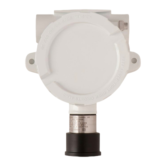
XDI (WIN)–15/30J (WIN)
TOXIC/OXYGEN – TRANSMITTER
(PCB 337 UPGRADE FROM PCB 204)
Technical Sheet ref C1882A v2.0
Electrochemical cells
POWER SUPPLY
15 to 30vDC 24v nominal
SET UP PROCEDURE
Direct Sensor – 3 wire - 4~20mA
New sensors are supplied ready to connect to a system with all jumpers inserted. This procedure shows
how to recalibrate as part of routine maintenance or cell replacement.
The first part is to set up the 4-20mA section which is produced by the CELL circuit. Note some cells take
time to stabilise. If used as 3 wire, only steps 1 to 5 are required.
1.
Connect the cell to terminal J14 and use +24V, 0V and 4~20mA connections on terminal J2 for 3 wire.
2. Measure the output current mV=mA at test pins TP2/TP3 and adjust reading to 4mA using the Zero pot.
LED D9 will go green.
3. Apply span gas to cell and adjust Gain pot to give correct mV reading at test pins TP2/TP3.
NOTE: at 50% span gas, the mV reading at TP2/TP3 should be 12mV.
4. Remove the span gas and re-adjust Zero pot to 4mV if required.
4 wire CANbus / 3 wire 4~20mA with processor communication
5. With power applied ensure that MPU led is flashing and the CAN led is on or flashing.
6. Connect USB-A to USB Micro B lead to J11 connector and to a PC running GDS Terminal at 4800 baud.
Ensure jumper J17 is fitted before programming.
7. The terminal output screen shows continuous data output/ commands and allows input from the PC
keyboard.
8. Select COM Port – Note each new sensor connected requires a new COM Port to be connected to.
9. Press 'Space Bar' loads sensor information.
10. Press 'C' enters calibration mode
11. Press 'G' to change the gas type to match the cell being used. NOTE: the range of the new gas has a
default value but can be changed by pressing 'R'.
12. Press 'A' to change the address of this sensor if required.
13. Press 'N' to select the number of decimal places to 1 or 2, (ie: dp=1 or dp=2)
14. When in clean air, the sensor is zeroed by adjusting 'Zero' pot until LED 'D9' goes green, 4mA should
be present on 'TP2' and 'TP3'.
15. Then apply span gas and press 'S' to enter span mode, obtain correct mV reading for test gas used by
adjusting 'Gain Pot'. The displayed reading can be made HIGHER by pressing 'H' LOWER by pressing 'L'
NOTE: This changes the mA reading on TP2/TP3. E.g. half range calibration gas = 12mV on TP2/3.
WatchGas | Klaverbaan 121 | 2908 KD Capelle aan den IJssel | The Netherlands | www.watchgas.com | info@watchgas.com
OUTPUTS
3 wire
4~20mA output
4 wire
CANbus
Relays
Low alarm
High alarm
Fault alarm
Inhibit option during servicing
Logging
Intervals – variable time
Roll over/stop
Storage – 2,880 readings
Requires
USB-A to USB Micro B cable
PC or laptop (dedicated)
GDS Terminal (download from GDS website)
SPCO
SPCO
0-5A@ 30v DC
SPCO
Advertisement

Related Manuals for WatchGas XDI Series


Summary of Contents for WatchGas XDI Series
- Page 1 ‘Gain Pot’. The displayed reading can be made HIGHER by pressing ‘H’ LOWER by pressing ‘L’ NOTE: This changes the mA reading on TP2/TP3. E.g. half range calibration gas = 12mV on TP2/3. WatchGas | Klaverbaan 121 | 2908 KD Capelle aan den IJssel | The Netherlands | www.watchgas.com | info@watchgas.com...
- Page 2 With no magnets present, the display will return to normal after a few seconds time out. WatchGas | Klaverbaan 121 | 2908 KD Capelle aan den IJssel | The Netherlands | www.watchgas.com | info@watchgas.com...
- Page 3 ©2022 WatchGas B.V. WatchGas is dedicated to continuously improving its products. Therefore, the specifications and features mentioned in this datasheet are subject to change without prior notice. WatchGas | Klaverbaan 121 | 2908 KD Capelle aan den IJssel | The Netherlands | www.watchgas.com | info@watchgas.com...