
Related Manuals for Trane IPG315D


Summary of Contents for Trane IPG315D
- Page 1 User Guide For controller on CXAO / RTXB heat pumps CGCM / CXCM 2 circuit units CNT-SVU005C-GB Original instructions...
-
Page 2: Table Of Contents
Table of contents Advanced electronics ....................3 Technical Specifications ..................... 4 Display description ..................... 6 Submenu ........................7 Operating Variables ....................8 Unit startup ......................... 8 Set Point ........................10 Energy Saving, Auto On/Off, ..................11 Dynamic Set Point………………………………………………………………………….12 Alarm display ......................13 D-Log Files Management .................. -
Page 3: Advanced Electronics
WARNING Supply the unit at least 24 hours before the initial startup to heat the compressor oil. In conditions of low water temperature, the pumps could be started in order to avoid freezing conditions. In order to avoid the breaking of heat exchangers due to water hammer, be sure to keep to water valves open. Failure to follow these instructions will void the warranty. -
Page 4: Technical Specifications
Technical Specifications IPG315D: Power supply: 24V AC/DC Digital inputs: 20 opto-insulated at 24Volt AC current on the contact Analog inputs: 10 configurables: 0÷5V, 4÷20mA, NTC, PTC, digital input Analog outputs Opto-Insulated: 2 configurables: 0÷10V, external relay driving, PWM signal 4 configurables: 0÷10V signal, external relay driving Relay outputs: 10 x 5(2) A @ 250V SPST + 5 SSR type Remote terminal N°... - Page 5 IPG108D / IPG108E: Power supply: 24V AC/DC Digital inputs: 11 opto-insulated at 24Volt AC current on the contact Analog inputs : 6 configurables: 0÷5V, 4÷20mA, NTC, PTC, digital input Analog outputs Opto-Insulated: 4 configurables: 0÷10V signal, external relay driving Relay outputs 8 x 5(2) A @ 250V SPST Remote terminal N°...
-
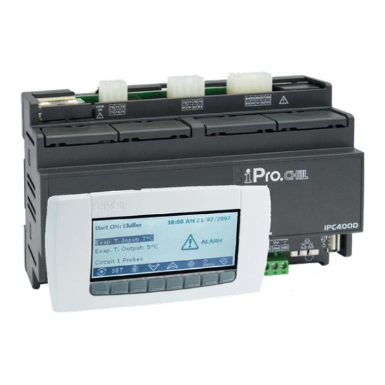
Page 6: Display Description
Display description Through the visual keyboard LCD display, you can monitor and change the status of the unit, using the 8 buttons positioned in the lower part of the keypad. Available information on display: At the unit startup, the main screen will be as follows: In case the unit is controlled by remote or during shutdown by time slot, the main screen will be: Through the selection keys you can enter in the sub-sections of the main screen, where you can view respectively:... -
Page 7: Submenu
Submenu The LCD display provides a simple and immediate interaction with the unit. Pressing the "SERVICE" button, you can enter in the screens dedicated to the displaying and/or to the configuration of components and user parameters of the unit. Using the arrow keys you can select the below areas reserved for displaying the features of each component. -
Page 8: Operating Variables
Operating Variables Pressing the "Circ" button, you can see the status of all unit components and the value read by the pressure transducers. In this way it is possible to make a quick check on how the unit is working. In these screens, you can see, at first, the state of all the compressors, with the status indication of any capacity control or the percentage of the 0-10V signal supplied from the device to the continuous modulation with frequency and if preventive functions “unloading”... -
Page 9: Unit Startup
Unit Startup To activate the unit press for more than 2 seconds the button indicated by the symbol of the sun , until the label “Unit Stand-by” is displayed. , or with the snow Following the activation, on the main screen, according to the selected mode, you will see the label “Unit ON: Cooling”, if you selected the summer mode, or “Unit ON: Heating”, if you selected the winter mode, and the button of the other mode will disappear. -
Page 10: Setpoint
SetPoint Pressing the "SET" button on the main screen, you enter in the screen shown below. In this menu you can set the cold “Chiller” and the hot “Recovery” set point. To change the value, highlight the set point to be changed using the arrow keys, press the Set button to enable editing, take it to the desired value using the UP or Down buttons and press Set again to confirm. -
Page 11: Energy Saving, Auto On/Off
Energy Saving & Auto On/Off Enabling the Energy Saving and setting the appropriate time slots within the sub-menu “Time bands” marked with the icon , and the parameters ES, table in Chapter 9, for the increase or decrease in the set point, the unit will follow a new value of “Real Set” calculated by an algorithm based on the parameters set according to the desired temperature curve, at the times you want. -
Page 12: Dynamic Set Point
Dynamic Set Point Enabling the Dynamic Set Point and setting the appropriate parameters for the increase or decrease of the set point and the range of outdoor temperatures in which this feature must be active, the Pa- rameters table in under SD the controller will change the set point continuously according to a propor- tional law. -
Page 13: Alarm Display
Alarm display The system is able to identify all the alarms that may damage the unit. When any type of fault or error on the unit occurs, the alarm symbol flashes on the display and the buzzer will be on. Press any key to turn the buzz off. -
Page 14: D-Log Files Management
D-Log Files Management The controller records on a non-volatile memory, approximately the last 4 days of work. You can download these log files directly to a USB stick, or on your PC by connecting properly to the controller. To download these files on a USB stick, plug into the USB port and navigate through the menu func- tions until you see In this menu select “files log management”, and inside select “Send all logs to a USB”... -
Page 15: Online Datalogger
Online Datalogger The device is equipped with a web page where you can view and record all the main operating data with a record time that can be set from 3 to 60 seconds. To use this feature of the microprocessor is necessary to connect the PC to the card via LAN cable cross type. -
Page 16: Remote Control
Remote Control You can control the unit remotely in three different ways: Free contacts reported in customer terminal block (X); Bus protocol; Remote keypad Remote Control via Free Contacts On the customer terminal block (X) are reported free terminals where you can connect any type of thermostat able to provide a current pulse to close the relay to active the unit, and any boards to read an alarm state. -
Page 17: Controlling The Unit Remotely By Bus Protocol
Remote Control via Bus On the control unit device is available a serial port RS485 with MODBUS or Bacnet MSTP protocol, to use this type of connection please respect the connection diagram below, respecting a bus connection type, avoiding the creation of stars. You can use the RS485 port Slave, depending on the position of the instrument in the network, only if you do not already committed to control the unit. -
Page 18: Controlling The Unit Remotely By Remote Keypad
Remote Control via Remote Keypad You can control the unit remotely, using a second keypad, connected in parallel to the one present on the unit. Also for this type of connection you have to respect the connection diagram below, respecting a bus connection type, thus avoiding the creation of stars. -
Page 19: User Parameter Table
User Parameters Table The parameters are organized in macro groups. Below are the areas dedicated for programming of user parameters: Thermoregulation parameters Dynamic set point parameters Energy saving parameters Remote S/W & Automatic Change Over Thermoregulation parameters Parameters Description u.m. Resolution Summer set point ST02... - Page 20 Monday 0 = No time band 1 = Time band 1 2 = Time band 2 3 = Time band 1 & 2 4 = Time band 3 5 = Time band 1 & 3 6 = Time band 2 & 3 7 = All time band Tuesday 0 = No time band...
- Page 21 ES15 Summer differential Energy saving 25.0 °C ES16 Winter increase set energy saving -50.0 110.0 °C ES17 Winter differential Energy saving 25.0 °C Automatic on/off by time band ES18 Monday 0 = No time band 1 = Time band 1 2 = Time band 2 3 = Time band 1 &...
- Page 22 HVAC systems, comprehensive building services, and parts. For more information, visit www.Trane.com. Trane has a policy of continuous product and product data improvement and reserves the right to change design and specifications without notice. © 2015 Trane All rights reserved...
Need help?
Do you have a question about the IPG315D and is the answer not in the manual?
Questions and answers