
Subscribe to Our Youtube Channel
Related Manuals for HMS Networks Anybus Communicator ABC4018


Summary of Contents for HMS Networks Anybus Communicator ABC4018
- Page 1 ENGLISH ® ™ Anybus Communicator - Modbus TCP Server to PROFIBUS DP Device USER MANUAL SCM-1202-201 Version 1.0 Publication date 2022-08-31...
- Page 2 The information in this document shall therefore not be construed as a commitment on the part of HMS Networks and is subject to change without notice. HMS Networks makes no commitment to update or keep current the information in this document.
-
Page 3: Table Of Contents
® ™ Anybus Communicator - Modbus TCP Server to PROFIBUS DP Device Table of Contents 1. Preface ..........................1 1.1. About This Document ......................1 1.2. Document Conventions ..................... 1 1.3. Trademarks ........................2 2. Safety ............................ 3 2.1. Intended Use ........................3 2.2. - Page 4 ® ™ Anybus Communicator - Modbus TCP Server to PROFIBUS DP Device 6.9.2. View and Edit Configuration Notes ................38 7. PLC Configuration ........................40 7.1. Export Product GSD File ....................40 7.2. Addressing and Register Mapping ..................40 7.2.1. Data From Modbus TCP Network to Serial-Subnet ............40 7.2.2.
-
Page 5: Preface
® ™ Preface Anybus Communicator - Modbus TCP Server to PROFIBUS DP Device 1. Preface 1.1. About This Document ® ™ This document describes how to install and configure Anybus Communicator For additional documentation and software downloads, FAQs, troubleshooting guides and technical support, please visit www.anybus.com/support. -
Page 6: Trademarks
Additional information which may facilitate installation and/or operation. Helpful advice and suggestions. 1.3. Trademarks ® Anybus is a registered trademark of HMS Networks. All other trademarks are the property of their respective holders. Page 2 of 60 SCM-1202-201 Version 1.0... -
Page 7: Safety
® ™ Safety Anybus Communicator - Modbus TCP Server to PROFIBUS DP Device 2. Safety 2.1. Intended Use The intended use of this equipment is as a communication interface and gateway. The equipment receives and transmits data on various physical layers and connection types. If this equipment is used in a manner not specified by the manufacturer, the protection provided by the equipment may be impaired. -
Page 8: Preparation
® ™ Anybus Communicator - Modbus TCP Server to PROFIBUS DP Device Preparation 3. Preparation 3.1. Cabling Have the following cables available: • Ethernet cable for configuration • Ethernet cable for connecting to network • PROFIBUS cable for connecting to network •... -
Page 9: Hms Software Applications
® ™ HMS Software Applications Anybus Communicator - Modbus TCP Server to PROFIBUS DP Device 3.5. HMS Software Applications Download the software installation files and user documentation from www.anybus.com/support. IPconfig Use the HMS software application IPconfig and scan your network to discover and change the Communicator IP address and to access the Communicator built-in web interface. -
Page 10: About Anybus Communicator
® ™ Anybus Communicator - Modbus TCP Server to PROFIBUS DP Device About Anybus Communicator 4. About Anybus Communicator 4.1. How the Communication Works Figure 1. Process data traffic overview The Communicator enables communication between a Master device connected to a Modbus TCP network and a Master device connected to a PROFIBUS network. -
Page 11: How The Data Exchange Works
® ™ How the Data Exchange Works Anybus Communicator - Modbus TCP Server to PROFIBUS DP Device 4.2. How the Data Exchange Works Figure 2. The Communicator internal memory areas The data exchanged between the Communicator and the Modbus TCP and the PROFIBUS resides in the Communicator internal memory buffer. -
Page 12: Installation
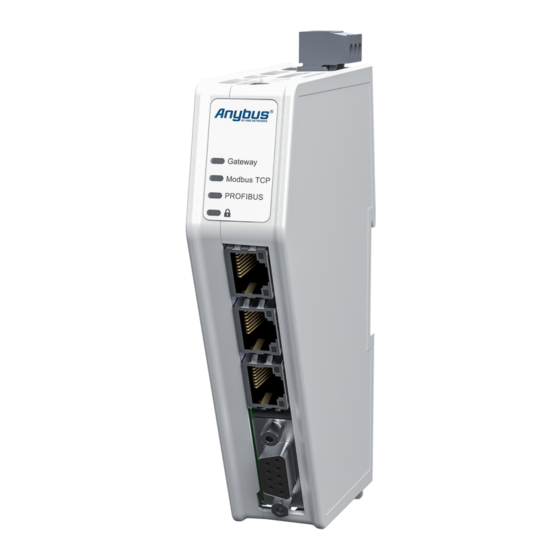
® ™ Anybus Communicator - Modbus TCP Server to PROFIBUS DP Device Installation 5. Installation 5.1. External Parts Figure 3. External parts A. Power connector Modbus TCP port x 2 Security switch B. Rotary Switch x 3 G. PROFIBUS DSUB connector K. -
Page 13: Din Rail Mounting
® ™ DIN Rail Mounting Anybus Communicator - Modbus TCP Server to PROFIBUS DP Device 5.2. DIN Rail Mounting IMPORTANT The equipment must be electrically grounded through the DIN rail for EMC compliance. Make sure that the equipment is correctly mounted on the rail and that the rail is properly grounded. Figure 4. -
Page 14: Connect To Modbus Tcp Network
® ™ Anybus Communicator - Modbus TCP Server to PROFIBUS DP Device Connect to Modbus TCP Network 5.3. Connect to Modbus TCP Network Figure 5. Connect to Modbus TCP network 1. Connect the Communicator, upper connector, to your Modbus TCP network. EtherNet/IP Connector Description Not used... -
Page 15: Connect To Profibus Network
® ™ Connect to PROFIBUS Network Anybus Communicator - Modbus TCP Server to PROFIBUS DP Device 5.4. Connect to PROFIBUS Network Figure 6. Connect to PROFIBUS network 1. Connect the Communicator, lower connector, to your PROFIBUS network. PROFIBUS Connector Description Shield Not used Line B... -
Page 16: Rotary Switch Settings
® ™ Anybus Communicator - Modbus TCP Server to PROFIBUS DP Device Rotary Switch Settings 5.5. Rotary Switch Settings 5.5.1. Rotary Switches Default Setting By default, the value on the three rotary switches are set to 000. Figure 7. Rotary switches default setting 000. Page 12 of 60 SCM-1202-201 Version 1.0... -
Page 17: Set A Node Address With Rotary Switches
® ™ Rotary Switch Settings Anybus Communicator - Modbus TCP Server to PROFIBUS DP Device 5.5.2. Set a Node Address with Rotary Switches About the Rotary Switch Settings Use Windows Calculator (or similar application) to convert between hexadecimal (hex) and decimal (dec). - Page 18 ® ™ Anybus Communicator - Modbus TCP Server to PROFIBUS DP Device Rotary Switch Settings Before You Begin Ensure that the Communicator is disconnected from power. Figure 8. Disconnect Communicator from power Procedure Use a screwdriver to change the rotary switch position. Ensure that the rotary switches engage correctly.
- Page 19 ® ™ Rotary Switch Settings Anybus Communicator - Modbus TCP Server to PROFIBUS DP Device Example 1. To set the node address 12 hex = 18 dec 1. The rear rotary switch A is not used, ensure that it is set to 0. 2.
- Page 20 ® ™ Anybus Communicator - Modbus TCP Server to PROFIBUS DP Device Rotary Switch Settings To Do Next Connect the Communicator to power. See Connect to Power (page 17). Figure 9. Connect Communicator to power Result The set node address is active as soon as the Communicator is powered on. NOTE Changing the address settings on the rotary switches during operation is ignored.
-
Page 21: Connect To Power
® ™ Connect to Power Anybus Communicator - Modbus TCP Server to PROFIBUS DP Device 5.6. Connect to Power CAUTION Ensure that the power supply is turned off before connecting it to the equipment. IMPORTANT Using the wrong type of power supply can damage the equipment. Ensure that the power supply is connected properly and of the recommended type. -
Page 22: Security Switch
® ™ Anybus Communicator - Modbus TCP Server to PROFIBUS DP Device Security Switch 5.7. Security Switch When the security switch is in its locked position, the Communicator built-in web interface can not be accessed and the Communicator can not be configured using the built-in web interface. Network specific parameters, configured via the PLC is still available. - Page 23 ® ™ Security Switch Anybus Communicator - Modbus TCP Server to PROFIBUS DP Device Security Switch Status LED Figure 12. Security switch locked status LED When the security switch is in its: • locked position, the security switch status LED turn solid green. •...
-
Page 24: Lock The Cables
® ™ Anybus Communicator - Modbus TCP Server to PROFIBUS DP Device Lock the Cables 5.8. Lock the Cables Figure 13. Lock the cables To strain relieve the cables, place a cable tie in the holder and lock the cables. Page 20 of 60 SCM-1202-201 Version 1.0... -
Page 25: Din Rail Demount
® ™ DIN Rail Demount Anybus Communicator - Modbus TCP Server to PROFIBUS DP Device 5.9. DIN Rail Demount Before You Begin IMPORTANT Be careful when removing the Communicator from the DIN-rail. If not removed properly, the DIN rail locking mechanism and the product cover can break. Have a flat-blade screwdriver, size 5.5 mm, available. - Page 26 ® ™ Anybus Communicator - Modbus TCP Server to PROFIBUS DP Device DIN Rail Demount Hold the screwdriver in the DIN rail locking mechanism while you unhook the Communicator from the DIN rail. Figure 15. Unhook the Communicator Page 22 of 60 SCM-1202-201 Version 1.0...
-
Page 27: Communicator Configuration
® ™ Communicator Configuration Anybus Communicator - Modbus TCP Server to PROFIBUS DP Device 6. Communicator Configuration 6.1. Connect the Communicator Procedure Connect to Modbus TCP and PROFIBUS network Network 1 = Modbus TCP Network 2 = PROFIBUS Connect to PC and Power Connect an Ethernet cable between the Communicator and your PC. -
Page 28: Access The Built-In Web Interface From Hms Ipconfig
® ™ Anybus Communicator - Modbus TCP Server to PROFIBUS DP Device Access the Built-In Web Interface From HMS IPconfig 6.2. Access the Built-In Web Interface From HMS IPconfig Before You Begin Download the software application HMS IPconfig installation files and user documentation from www.anybus.com/support. - Page 29 ® ™ Access the Built-In Web Interface From HMS IPconfig Anybus Communicator - Modbus TCP Server to PROFIBUS DP Device To open the Open web page built-in web interface, click Communicator. Result You are redirected to the Communicator built-in web interface Home page. SCM-1202-201 Version 1.0 Page 25 of 60...
-
Page 30: Access The Built-In Web Interface From A Web Browser
® ™ Anybus Communicator - Modbus TCP Server to PROFIBUS DP Device Access the Built-In Web Interface From a Web Browser 6.3. Access the Built-In Web Interface From a Web Browser Before You Begin NOTE The Communicator configuration port default IP address is 192.168.0.10. NOTE To access the Communicator built-in web interface, ensure that Port 80 TCP is open in your Firewall. -
Page 31: Communicator Built-In Web Interface Overview
® ™ Communicator Built-In Web Interface Overview Anybus Communicator - Modbus TCP Server to PROFIBUS DP Device 6.4. Communicator Built-In Web Interface Overview Use the Communicator built-in web interface to configure, maintain and troubleshoot the Communicator. Figure 16. The Communicator built-in web interface Home page Menu item Description Home... -
Page 32: Modbus Tcp Settings
® ™ Anybus Communicator - Modbus TCP Server to PROFIBUS DP Device Modbus TCP Settings 6.5. Modbus TCP Settings 6.5.1. Modbus TCP IP Settings To Use DHCP Server Figure 17. IP Settings, DHCP enabled By default, the IP settings are provided by the high level network DHCP server. The DHCP enabled checkbox is selected. - Page 33 ® ™ Modbus TCP Settings Anybus Communicator - Modbus TCP Server to PROFIBUS DP Device To Configure IP Settings Manually Figure 18. Modbus TCP IP Settings, DCHP disabled 1. Deselect the DHCP enabled checkbox. 2. Configure the IP settings. Setting Description IP address The Modbus TCP network IP address in IPv4 dot-decimal notation...
-
Page 34: Timeout Time Settings
® ™ Anybus Communicator - Modbus TCP Server to PROFIBUS DP Device Modbus TCP Settings Naming the Host Figure 19. IP Settings Hostname You can label the Communicator. • The maximum allowed length of the Hostname is 64 characters. • No symbol characters, punctuation characters, or whitespace are permitted. •... -
Page 35: Profibus Settings
® ™ PROFIBUS Settings Anybus Communicator - Modbus TCP Server to PROFIBUS DP Device 6.6. PROFIBUS Settings 6.6.1. PROFIBUS Address Settings NOTE Ensure that the Communicator rotary switches are sett to 000. Figure 21. PROFIBUS address setting In the PROFIBUS address field, enter the Communicator node address. 6.6.2. -
Page 36: I/O Configuration
® ™ Anybus Communicator - Modbus TCP Server to PROFIBUS DP Device I/O Configuration 6.7. I/O Configuration Figure 23. I/O configuration page Enter the desired Size for the network input data and output data. By default, the Communicator is set to use the same I/O sizes for both the Modbus TCP and the PROFIBUS networks. - Page 37 ® ™ I/O Configuration Anybus Communicator - Modbus TCP Server to PROFIBUS DP Device Convert Between Big-Endian and Little-Endian To convert between big-endian and little-endian you must reverse the byte order. Figure 24. I/O data map, Endian swap To reverse the byte order: In the web-interface left sidebar menu, click .
- Page 38 ® ™ Anybus Communicator - Modbus TCP Server to PROFIBUS DP Device I/O Configuration Build Detailed Endian Swap If you have multiple data types, you can use the Detailed endian swap to change different parts of the data area in different ways. Figure 25.
- Page 39 ® ™ I/O Configuration Anybus Communicator - Modbus TCP Server to PROFIBUS DP Device • To duplicate an endian swap object: Select the checkbox in front of the endian swap object that you want to duplicate and click the Duplicate selected button. You can select multiple endian swap objects and duplicate the group.
-
Page 40: Apply Configuration
® ™ Anybus Communicator - Modbus TCP Server to PROFIBUS DP Device Apply Configuration 6.8. Apply Configuration Before You Begin NOTE When you apply the configuration, any existing configuration is overwritten. Figure 29. Before you can apply the configuration, ensure that there is no active communication on the Modbus TCP network or the PROFIBUS network where the Communicator is connected. -
Page 41: Configuration Notes
® ™ Configuration Notes Anybus Communicator - Modbus TCP Server to PROFIBUS DP Device 6.9. Configuration Notes You can add notes to describe the Communicator configuration. 6.9.1. Add Configuration Note To open the Configuration Notes window, click on the comments icon Figure 30. -
Page 42: View And Edit Configuration Notes
® ™ Anybus Communicator - Modbus TCP Server to PROFIBUS DP Device Configuration Notes Write your configuration note and click accept Figure 32. Write a configuration note The configuration note is added to the list. To close the window, click close 6.9.2. - Page 43 ® ™ Configuration Notes Anybus Communicator - Modbus TCP Server to PROFIBUS DP Device Figure 34. Example: The Configuration Notes window with added notes SCM-1202-201 Version 1.0 Page 39 of 60...
-
Page 44: Plc Configuration
® ™ Anybus Communicator - Modbus TCP Server to PROFIBUS DP Device PLC Configuration 7. PLC Configuration 7.1. Export Product GSD File Option for PROFIBUS DP Device. Option if the PLC program requires a product file, GSD (General Station Description) file, describing how the Communicator can be used on the high level network. -
Page 45: Idle Mode
® ™ Addressing and Register Mapping Anybus Communicator - Modbus TCP Server to PROFIBUS DP Device 7.2.3. Idle Mode Transaction Holding Register Description Enter/Exit Idle Mode 0x1004 Used by the Modbus TCP client to indicate an idle/offline mode on the network. SCM-1202-201 Version 1.0 Page 41 of 60... -
Page 46: Verify Operation
® ™ Anybus Communicator - Modbus TCP Server to PROFIBUS DP Device Verify Operation 8. Verify Operation 8.1. Communicator Status Monitor On the Home page, you can get a quick overview of the network and the Communicator operating status. Figure 36. Home page Gateway status Overview the Communicator LED indications remotely. - Page 47 ® ™ Communicator Status Monitor Anybus Communicator - Modbus TCP Server to PROFIBUS DP Device Status Symbols Symbol Description Internal error has occurred and operation cannot be guaranteed. Out of Specification. Check Function: • Initial state where non network components are started and configured. •...
-
Page 48: Communicator Led Indicators
® ™ Anybus Communicator - Modbus TCP Server to PROFIBUS DP Device Communicator LED Indicators 8.2. Communicator LED Indicators NOTE Before you can verify operation you must configure the Communicator. Figure 37. Gateway status (A), Lower connector (B), Upper connector (C) and (D) Security Switch LED A - Gateway status Operation Status Description... - Page 49 ® ™ Communicator LED Indicators Anybus Communicator - Modbus TCP Server to PROFIBUS DP Device LED B - Modbus TCP, Upper connector Operation Status EtherCAT EtherNet/IP Modbus TCP PROFINET Red, solid FATAL event Duplicated EtherNet/IP IP IP address conflict detected FATAL event address Red, one flash...
-
Page 50: Maintenance
® ™ Anybus Communicator - Modbus TCP Server to PROFIBUS DP Device Maintenance 9. Maintenance 9.1. Configuration File Handling 9.1.1. Export Configuration You can export the current configuration, in order to import and use the same settings to configure additional Communicator. -
Page 51: Import Configuration
® ™ Configuration File Handling Anybus Communicator - Modbus TCP Server to PROFIBUS DP Device 9.1.2. Import Configuration To easily configure multiple Communicator with the same settings, you can import a configuration file. Before You Begin The supported file format is .conf. Procedure Figure 39. -
Page 52: Clear And Revert Configuration
® ™ Anybus Communicator - Modbus TCP Server to PROFIBUS DP Device Clear and Revert Configuration 9.2. Clear and Revert Configuration You can restore all settings in a configuration to the default settings. Procedure Figure 40. Files & firmware page To Clear the Configuration When you want to clear a configuration and return to the default settings. -
Page 53: Firmware Management
® ™ Firmware Management Anybus Communicator - Modbus TCP Server to PROFIBUS DP Device 9.3. Firmware Management 9.3.1. View the Firmware Version On the Support page, you can view the current applied firmware version. Figure 41. Support page, Product information example 9.3.2. -
Page 54: Update Firmware
® ™ Anybus Communicator - Modbus TCP Server to PROFIBUS DP Device Firmware Management 9.3.4. Update Firmware Before You Begin Ensure that the Communicator is disconnected from the OT networks. Procedure Figure 42. Files & firmware page To update the firmware: On the Files &... -
Page 55: Troubleshooting
® ™ Troubleshooting Anybus Communicator - Modbus TCP Server to PROFIBUS DP Device 10. Troubleshooting 10.1. Diagnostics 10.1.1. I/O Data On the Diagnostics, I/O data page you can monitor how the data flow between the Modbus TCP side and the PROFIBUS side, including any configured endian conversions. -
Page 56: Event Log
® ™ Anybus Communicator - Modbus TCP Server to PROFIBUS DP Device Diagnostics 10.1.2. Event Log Figure 44. Event log page example How To Analyze the Information The log follows the FIFO principle, first in and first out. The oldest (first) value is processed first. Time (d:hh:mm:ss.ms) The date and time when the event occurred. -
Page 57: Reset To Factory Settings
® ™ Reset to Factory Settings Anybus Communicator - Modbus TCP Server to PROFIBUS DP Device 10.2. Reset to Factory Settings Before You Begin Procedure To reset the Communicator: Disconnect the Communicator from power. Figure 45. Disconnect power Use a pointed object, such as a ballpoint pen to press and hold the Reset button. Figure 46. - Page 58 ® ™ Anybus Communicator - Modbus TCP Server to PROFIBUS DP Device Reset to Factory Settings While holding the reset button, reconnect the Communicator to power. Figure 47. Hold Reset button and reconnect power Release the reset button. The Communicator enters exception state. Reboot the Communicator.
-
Page 59: Firmware Upgrade Error Management
® ™ Firmware Upgrade Error Management Anybus Communicator - Modbus TCP Server to PROFIBUS DP Device 10.3. Firmware Upgrade Error Management If the firmware update process is interrupted or if the power is lost during the update process, the Communicator goes into fallback mode. The last working firmware is still available on the flash, but it is not active. - Page 60 ® ™ Anybus Communicator - Modbus TCP Server to PROFIBUS DP Device Firmware Upgrade Error Management Leave the Communicator for 10 minutes. The Gateway status led indicator flashes red and green until the firmware upgrade is completed. Figure 51. Firmware upgrade LED indication Result The Communicator recover and return to normal operation.
-
Page 61: Support
® ™ Support Anybus Communicator - Modbus TCP Server to PROFIBUS DP Device 10.4. Support 10.4.1. Support Package Figure 53. Support page example Before you create a ticket for technical support, generate a support package. The support package contains information about what has occurred and will help the Anybus technical support team resolve the support case as quickly and efficiently as possible. -
Page 62: Technical Data
® ™ Anybus Communicator - Modbus TCP Server to PROFIBUS DP Device Technical Data 11. Technical Data For complete technical specifications and regulatory compliance information, please visit www.anybus.com. 11.1. Technical Specifications Article identification ABC4018 Configuration connector RJ45 Upper connector RJ45 x 2 Lower connector 9-pin D-sub Power connector... - Page 63 This page is intentionally left blank.
- Page 64 This page is intentionally left blank.
Need help?
Do you have a question about the Anybus Communicator ABC4018 and is the answer not in the manual?
Questions and answers