Table of Contents
Advertisement
Quick Links
ZMID4200MROT36001
Rotary Application Module
Description
The ZMID4200 application modules provide an easy
demonstration of Renesas' ZMID4200 inductive
sensing solutions for specific application cases. The
typical sensor performance for a defined application
use case can be evaluated via reference
measurements performed with the application
module.
Renesas' ZMID4200MROT36001 Rotary Application
Module demonstrates inductive rotary position
sensing. The Application Module can be
programmed for a specific application range using
ZMID-COMBOARD, which is separately available.
The Rotary Application Module Sensor PCB can be
easily attached to an existing mechanical
configuration for prototyping.
Kit Contents
Rotary Application Module Sensor PCB
■
■
Sensor Target, Target Holder, Rotation Axis, and
Knob
■
Module Connection Cable
■
Quick Start Guide and Kit Disclaimer
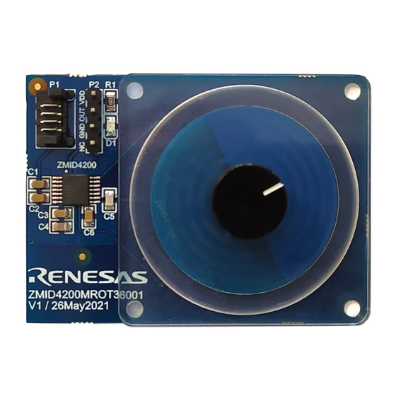
ZMID4200MROT36001 Rotary Application Module Sensor PCB
P2 Appli c ation Module
Interface Header
NC, GND, OUT, VDD
P1 Appli c ation Module
Connector for the
ZMID-COMBOARD
(Separately Available)
Power Indicator LED
ZMID4200 Sensor IC
Measurement Range: 360°
Coil Range: 360°
Target: 180° (50%)
Rev.1.0
Jul 21, 2021
Features
Easy application prototyping
■
■
Measurement reports available.
■
Programmable output slope and linearization
■
Tolerance to mechanical misalignment
■
No magnets required; reduces cost
■
Module design data, ZMID4200 EVK Application
Software, and user manual available online
depending on the module:
http://www.renesas.com/ZMID4200stkit
Rotary Module Summary
Measurement range: 360 (using a 50% target)
■
■
Output resolution:
●
10-bit Analog Output = 0.35
●
10-bit PWM Output = 0.35
●
12-bit SENT Output = 0.09
Target Positions
55mm
User Guide
Page 1
© 2021 Renesas Electronics
Advertisement
Table of Contents

Related Manuals for Renesas ZMID4200MROT36001


Summary of Contents for Renesas ZMID4200MROT36001
- Page 1 Sensor Target, Target Holder, Rotation Axis, and Knob ■ Module Connection Cable ■ Quick Start Guide and Kit Disclaimer ZMID4200MROT36001 Rotary Application Module Sensor PCB P2 Appli c ation Module Interface Header NC, GND, OUT, VDD P1 Appli c ation Module Connector for the...
- Page 2 ZMID4200MROT36001 / Rotary Application Module Important Notes Disclaimer Integrated Device Technology, Inc. and its affiliated companies (herein referred to as “Renesas”) shall not be liable for any damages arising out of defects resulting from delivered hardware or software (ii) non-observance of instructions contained in this manual and in any other documentation provided to user, or (iii) misuse, abuse, use under abnormal conditions, or alteration by anyone other than Renesas.
-
Page 3: Table Of Contents
ZMID4200MROT36001 / Rotary Application Module Contents Introduction ..............................5 Module Description ..........................5 1.1.1. Electrical Data ......................... 5 1.1.2. Electrical Connections to interfacing an Application MCU ............6 1.1.3. Design Documentation ......................6 Getting Started............................6 1.2.1. Module Hardware Connections ....................6 1.2.2. - Page 4 ZMID4200MROT36001 / Rotary Application Module Table 4. Sensor Configuration for the Measurement ....................8 Table 5. Rotary Application Module Sensor PCB BOM ..................12 Rev.1.0 Page 4 Jul 21, 2021...
-
Page 5: Introduction
ZMID4200MROT36001 / Rotary Application Module 1. Introduction This user manual describes the ZMID4200MROT36001 Rotary Application Module. This application module is designed to measure the rotary movement of a sensor target using the ZMID4200 Inductive Position Sensor IC, which is connected to an application specific coil design and located on the Rotary Application Module Sensor PCB. -
Page 6: Electrical Connections To Interfacing An Application Mcu
The design data are available on the webpage (see page 1), or they can be requested from (see contact information on the last page). The support package contains the design files as well as the fabrication outputs for the ZMID4200MROT36001 Rotary Application Module including the following: ■... -
Page 7: Target Holder Assembly Instructions
ZMID4200MROT36001 / Rotary Application Module Connect to Application MCU Application Module Option A: Connect P2 to Application Controller Option B: Connect P1 to ZMID-COMBOARD for demonstration and programming User s Computer Connect to with ZMID420x EVK ZMID-COMBOARD Application Software Figure 1. Application Module Connections Table 3. -
Page 8: Sensor Configuration And Calibration
ZMID4200MROT36001 / Rotary Application Module Assembled Application Module Figure 2. Target Holder Assembly 1.2.3. Sensor Configuration and Calibration The application module is preconfigured for the mechanical configuration when using the target holder. If the Rotary Application Module Sensor PCB is mounted on any existing application with a mechanical configuration different from the application module mechanics, the sensor IC must be configured and programmed for the new setup. -
Page 9: Figure 3. Accuracy With Linearization At 1.5Mm Airgap (Ag150)
ZMID4200MROT36001 / Rotary Application Module Value 17C0 0400 0000 8200 8481 8500 8683 Name LinInt4 CoilOffset CalMode Trimming AGC0 AGC1 Mask Register Value 0080 1000 1100 B103 0838 0055 BFFF Name Trace0 Trace1 Misc Register Value 0000 0000 00C2 POS1Error_%... -
Page 10: Figure 4. Accuracy With Linearization At 1.5Mm Airgap And Effects Of Airgap Changes
ZMID4200MROT36001 / Rotary Application Module POS1Error_% Full-Scale Error in % Pos1 AG100 _XP00 0_YP00 POS1 Pos1 AG150 _XP00 0_YP00 -0.1 POS1 -0.2 Pos1 AG200 -0.3 _XP00 -0.4 0_YP00 POS1 Displacement deg Note: AG100 = 1mm airgap; AG150 = 1.5mm; and AG200 = 2.0mm airgap. -
Page 11: Rotary Application Module Sensor Pcb
ZMID4200MROT36001 / Rotary Application Module Pos1 POS1Error_% Full-Scale Error in % AG150 _XP00 0_YP0 POS1 Pos1 AG150 _XP00 0_YP0 POS1 Pos1 AG150 -0.1 _XP00 0_YP0 -0.2 POS1 -0.3 Pos1 AG150 _XP00 -0.4 0_YM0 Displacement deg POS1 Figure 6. Accuracy with Linearization at 1.5mm Airgap and Effects of Displacement in Y 3. -
Page 12: Layout
Layout For an appropriate coil design, specific tools to generate the coil pattern were used. These tools are available to Renesas customers if custom coil designs are needed. Note: Dimensions are in mm. Figure 8. Rotary Application Module Sensor PCB Layout and Dimensions Bill of Materials (BOM) Table 5. -
Page 13: Mechanical Components
ZMID4200MROT36001 / Rotary Application Module 4. Mechanical Components The Application Module is shipped together with a target holder which is used to move the target over the receiver coil for evaluation purposes. A description of the target holder mechanics is shown below. -
Page 14: Target Holder Knob
ZMID4200MROT36001 / Rotary Application Module Target Holder Knob The target knob is used to slide the target inside the target holder. Note: Dimensions are in mm. Figure 11. Sensor Target Knob Dimensions 5. Ordering Information Orderable Part Number Description ZMID4200MROT36001 Inductive Rotary Application Module with 360... - Page 15 Renesas Electronics products, if required. 5. You shall not alter, modify, copy, or reverse engineer any Renesas Electronics product, whether in whole or in part. Renesas Electronics disclaims any and all liability for any losses or damages incurred by you or third parties arising from such alteration, modification, copying or reverse engineering.
- Page 16 12. It is the responsibility of the buyer or distributor of Renesas Electronics products, or any other party who distributes, disposes of, or otherwise sells or transfers the product to a third party, to notify such third party in advance of the contents and conditions set forth in this document.
Need help?
Do you have a question about the ZMID4200MROT36001 and is the answer not in the manual?
Questions and answers