Advertisement
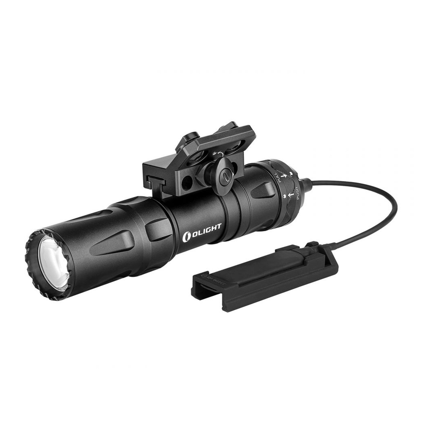
IN THE BOX

SPECIFICATIONS

All above specifications are test results based on ANSI/NEMA FL1-2009 Standard. The tests are performed using the battery included in the light.
NOTE:
The light output brightness will decrease as the battery voltage decreases.
USB MAGNETIC CHARGING CABLE -- MCC3
| Parameters | Specification |
| Charge cable | USB type A - magnetic charge connector, length: 0.5m |
| Input | USB A - Type DC 5V 2A |
| Charging pattern | CC&CV |
| Maximum charging current | 2A |
| Full-charged voltage | 4.2V±0.05V |
| Charge indication | Red: charging Green: full (over 95%) or disconnect with flashlight |
| Full-charged time | 5.5 hours (For reference only. When the USB power supply is insufficient to provide 5V 2A power capacity, the charging time will be longer) |
PRODUCT OVERVIEW

BATTERY INSTALLATION
Before first use, unscrew the tailcap and remove the insulating film within the battery compartment before screwing the tailcap back on tightly. If the battery needs to be changed, make sure that the positive polarity side of the battery faces toward the direction of the light head (the side of the LED).

AVAILABLE BATTERIES
- 1 x customized 5000mAh 21700 rechargeable lithium battery
CHARGING
VIBRATING POWER INDICATOR
It helps to alert if the battery is low (power<20% vibrate once every 5 minutes; power<10% vibrate once per minute; power< 5% vibrate once every 10 seconds).

- Before first use please fully charge the product.
- Connect the magnetic USB end of the charging cable (MCC3) to an external USB power source, then attach the other end of the magnetic charging cable to the charging port (best charging efficiency with more than 10W (5V 2A) USB power source). The red indicator means charging, green indicator means charging completed (battery power>95%).
- Only charge with standard MCC3, not compatible with other MCC.
PRODUCT INSTALLATION
- Rotate the button 90 degrees counterclockwise to unlock the product as the mark shows.

- Press the button and remove the product.


- Loosen the screws and install the rail mount in its desired position, then tighten the screws.


- Slide the product into the rail mount until you hear a click, then turn the button 90 degrees clockwise as the mark shows to fix the product.


REMOTE SWITCH INSTALLATION
- Attach the magnetic remote switch to the tail of the product (make sure the detent ring of the remote switch is unlocked).
- Push the ring forward to fix the remote switch.


- DO NOT throw the light directly into human eyes. This may cause temporary blindness, or permanent damage to the eyes.
- DO NOT cover the light head when the flashlight is on, or place the light head on the ground. The radiation energy of the light may cause damage to the flashlight itself, or even result in burning to flammable objects.
- DO NOT use Non-protected rechargeable batteries.

- Keep out of reach of children.
- DO NOT activate high mode repeatedly under high temperature to prevent the light body from overheating and hurting the user' s hand.
- The tail switch may not work while immersed in sea water or other conductive media. Please try to keep it clean and dry.
- If the light is about to be put aside for a long time or be transported, please unscrew the tailcap and remove the battery to cut off the circuit.
NOTICE
- DO NOT short circuit the switch cap with the ring outside it for a prolonged period. The short circuit in this case will result in a loss of current below 3mA, and may lead to a complete battery drain if it is in this state for too long.
HOW TO OPERATE
Click the tail switch lightly to produce a low light output or press the tail switch hard to produce a high light output.
Single click (click and release quickly) the tail switch to turn the flashlight on or off.
When you press and hold the switch, the flashlight will be in momentary mode; when you release the tail switch, it will turn off.
EU-Declaration of Conformity

EU-Declaration of Conformity can be found here CE:
https://olightworld.com/ec-declaration

VideosNew Olight Odin Review Video & Torture Test
Documents / Resources
References
Download manual
Here you can download full pdf version of manual, it may contain additional safety instructions, warranty information, FCC rules, etc.
Advertisement


Need help?
Do you have a question about the Odin and is the answer not in the manual?
Questions and answers