GORMAN-RUPP PUMPS PA6C60-4045T FT4-ESP Installation, Operation And Maintenance Manual
Hide thumbs
Also See for PA6C60-4045T FT4-ESP:

Related Manuals for GORMAN-RUPP PUMPS PA6C60-4045T FT4-ESP


Summary of Contents for GORMAN-RUPP PUMPS PA6C60-4045T FT4-ESP
- Page 1 OM-07428-01 April 15, 2021 INSTALLATION, OPERATION, AND MAINTENANCE MANUAL WITH PARTS LIST PA SERIES PUMP MODEL PA6C60-4045T FT4-ESP GORMAN‐RUPP PUMPS www.grpumps.com 2021 Gorman‐Rupp Pumps Printed in U.S.A.
- Page 2 Register your new Gorman‐Rupp pump online at www.grpumps.com Valid serial number and e‐mail address required. The engine exhaust from this product contains chemicals known to the State of California to cause cancer, birth defects or other reproductive harm. RECORD YOUR PUMP MODEL AND SERIAL NUMBER Please record your pump model and serial number in the spaces provided below.
-
Page 3: Table Of Contents
TABLE OF CONTENTS INTRODUCTION ..........PAGE I - 1 SAFETY ‐... - Page 4 TABLE OF CONTENTS (continued) PARTS LIST: Pump Model ............PAGE E - 3 Power Unit Kit .
-
Page 5: Introduction
PA SERIES OM-07428 INTRODUCTION Thank You for purchasing a Gorman‐Rupp pump. The following are used to alert personnel to proce Read this manual carefully to learn how to safely dures which require special attention, to those install and operate your pump. Failure to do so which could damage equipment, and to those could result in personal injury or damage to the which could be dangerous to personnel:... -
Page 6: Safety - Section A
PA SERIES OM-07428 SAFETY ‐ SECTION A This information applies to Prime Aire damage the pump or endanger person Series pumps. Refer to the manual ac nel as a result of pump failure. companying the engine or power source before attempting to begin oper ation. - Page 7 OM-07428 PA SERIES against a closed discharge valve, pump components will deteriorate, and the liquid could come to a boil, build pres sure, and cause the pump casing to rup Make sure the pump is level. Lower jack ture or explode. Momentary closure of a stands and chock the wheels, if so discharge valve is acceptable only equipped.
-
Page 8: Installation - Section B
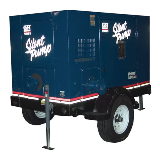
111.00 APPROX [ 2819,4 ] 58.75 [ 1492,2 ] Figure 1. Pump Model PA6C60-4045T FT4-ESP PREINSTALLATION INSPECTION a. Inspect the pump for cracks, dents, damaged threads, and other obvious damage. The pump assembly was inspected and tested be b. Check for and tighten loose attaching hard... -
Page 9: Battery Installation
OM-07428 PA SERIES c. Carefully read all tags, decals, and markings POSITIONING PUMP on the pump assembly, and perform all duties indicated. Note that the pump shaft rotates in the required direction. Death or serious personal injury and damage to the pump or components can occur if proper lifting procedures Only operate this pump in the direction in... -
Page 10: Suction And Discharge Piping
PA SERIES OM-07428 to secure them when filled with liquid and under pressure. Gauges If the pump has been mounted on a mov able base, do not attempt to operate the The pump is drilled and tapped for installing dis pump unless the unit is level. -
Page 11: Sealing
OM-07428 PA SERIES Sealing air to escape from the liquid before it is drawn into the suction inlet. Since even a slight leak will affect priming, head, If two suction lines are installed in a single sump, and capacity, especially when operating with a the flow paths may interact, reducing the efficiency high suction lift, all connections in the suction line of one or both pumps. -
Page 12: Discharge Lines
PA SERIES OM-07428 Figure 2. Recommended Minimum Suction Line Submergence vs. Velocity DISCHARGE LINES Siphoning If the application involves a high discharge head, gradually close the discharge Do not terminate the discharge line at a level lower than that of the liquid being pumped unless a si throttling valve before stopping the pump. -
Page 13: Float Switch Installation
OM-07428 PA SERIES Float Switch Installation pipe is available, attach the float switch cable to the standpipe in the sump at the approxi mate desired liquid level. The Float Switch autostart system employs either a single or double float switch, where a bulb raises or lowers (floats) with the liquid level, thus activating b. - Page 14 PA SERIES OM-07428 that the liquid in the priming chamber never fully Next, install a drain line between the pump drain freezes. and the wet well or sump. This line must remain submerged in the liquid below the pump down lev The second method involves configuring the el of the liquid level control device;...
-
Page 15: Operation - Section C
OM-07428 PA SERIES OPERATION - SECTION C Review all SAFETY information in Section A. cated (see LUBRICATION in MAINTENANCE AND REPAIR). Follow the instructions on all tags, labels and The pump will begin to prime upon startup. The air decals attached to the pump. in the suction line will be discharged from the educ... -
Page 16: Operation
OM-07428 PA SERIES AL'. After the engine starts and the unit is fully Liquid Temperature And Overheating primed, adjust the engine RPM until the desired The maximum liquid temperature for this pump is flow rate is achieved. 160_ F (71_C). Do not apply it at a higher operating temperature. -
Page 17: Stopping
OM-07428 PA SERIES vacuum suction gauge readings regularly to detect against the housing. Record this temperature for strainer blockage. future reference. Never introduce air or steam pressure into the A sudden increase in bearing temperatures is a pump casing or piping to remove a blockage. This warning that the bearings are at the point of failing could result in personal injury or damage to the to operate properly. -
Page 18: Troubleshooting - Section D
OM-07428 PA SERIES TROUBLESHOOTING - SECTION D Review all SAFETY information in Section A. 5. Close the suction and discharge valves. 6. Vent the pump slowly and cau tiously. 7. Drain the pump. Before attempting to open or service the pump: 1. - Page 19 OM-07428 PA SERIES TROUBLE POSSIBLE CAUSE PROBABLE REMEDY Check strainer and clean if neces Strainer clogged. PUMP STOPS OR FAILS TO DELIVER sary. RATED FLOW OR Check and clean check valve. Discharge check valve clogged. PRESSURE (cont.) Suction intake not submerged at Check installation and correct proper level or sump too small.
-
Page 20: Preventive Maintenance
OM-07428 PA SERIES TROUBLE POSSIBLE CAUSE PROBABLE REMEDY BEARINGS RUN Bearing temperature is high, but Check bearing temperature regu TOO HOT within limits. larly to monitor any increase. Low or incorrect lubricant. Check for proper type and level of lubricant. Suction and discharge lines not prop...
Need help?
Do you have a question about the PA6C60-4045T FT4-ESP and is the answer not in the manual?
Questions and answers