Table of Contents

Related Manuals for GORMAN-RUPP PUMPS PA4A60D-4045T FT4-ESP


Summary of Contents for GORMAN-RUPP PUMPS PA4A60D-4045T FT4-ESP
- Page 1 OM-07475-01 September 23, 2021 Rev. A - 8/16/23 INSTALLATION, OPERATION, AND MAINTENANCE MANUAL WITH PARTS LIST PA SERIESr PUMP MODEL PA4A60D‐4045T FT4‐ESP GORMAN‐RUPP PUMPS www.grpumps.com 2021 Gorman‐Rupp Pumps Printed in U.S.A.
- Page 2 Register your new Gorman‐Rupp pump online at www.grpumps.com Valid serial number and e‐mail address required. The engine exhaust from this product contains chemicals known to the State of California to cause cancer, birth defects or other reproductive harm. RECORD YOUR PUMP MODEL AND SERIAL NUMBER Please record your pump model and serial number in the spaces provided below.
-
Page 3: Table Of Contents
TABLE OF CONTENTS INTRODUCTION ..........PAGE I - 1 SAFETY ‐... - Page 4 TABLE OF CONTENTS (continued) Engine Fuel Filter ............PAGE C - 4 Engine Oil .
-
Page 5: Introduction
PA SERIES OM-07475 INTRODUCTION Thank You for purchasing a Gorman‐Rupp pump. HAZARD AND INSTRUCTION Read this manual carefully to learn how to safely DEFINITIONS install and operate your pump. Failure to do so could result in personal injury or damage to the The following are used to alert maintenance per... -
Page 6: Safety - Section A
PA SERIES OM-07475 SAFETY ‐ SECTION A This information applies to Prime Aire the positive battery cable before per Series pumps. Refer to the manual ac forming any maintenance. Failure to do companying the engine or power so may result in serious personal injury. source before attempting to begin oper... - Page 7 OM-07475 PA SERIES After the pump has been installed, make Make sure the pump is level. Lower jack certain that the pump and all piping or stands and chock the wheels, if so hose connections are tight, properly equipped. Use caution when positioning supported and secure before operation.
-
Page 8: Installation - Section B
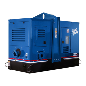
44.25 [ 2682,9 ] [ 1124,0 ] 51.00 [ 1295,4 ] Figure 1. Pump Model PA4A60D-4045T FT4-ESP PREINSTALLATION INSPECTION a. Inspect the pump for cracks, dents, damaged threads, and other obvious damage. The pump assembly was inspected and tested be... -
Page 9: Battery Installation
OM-07475 PA SERIES c. Carefully read all tags, decals, and markings POSITIONING PUMP on the pump assembly, and perform all duties indicated. Note that the pump shaft rotates in the required direction. Lifting Only operate this pump in the direction in Death or serious personal injury and dicated by the arrow on the pump body damage to the pump or components... -
Page 10: Suction And Discharge Piping
PA SERIES OM-07475 to secure them when filled with liquid and under pressure. Gauges If the pump has been mounted on a mov able base, do not attempt to operate the The pump is drilled and tapped for installing dis pump unless the unit is level. -
Page 11: Sealing
OM-07475 PA SERIES Sealing air to escape from the liquid before it is drawn into the suction inlet. Since even a slight leak will affect priming, head, If two suction lines are installed in a single sump, and capacity, especially when operating with a the flow paths may interact, reducing the efficiency high suction lift, all connections in the suction line of one or both pumps. -
Page 12: Discharge Lines
PA SERIES OM-07475 Figure 2. Recommended Minimum Suction Line Submergence vs. Velocity DISCHARGE LINES Siphoning If the application involves a high discharge head, gradually close the discharge Do not terminate the discharge line at a level lower than that of the liquid being pumped unless a si throttling valve before stopping the pump. -
Page 13: Float Switch Installation
OM-07475 PA SERIES Float Switch Installation pipe is available, attach the float switch cable to the standpipe in the sump at the approxi mate desired liquid level. The Float Switch autostart system employs either a single or double float switch, where a bulb raises or lowers (floats) with the liquid level, thus activating b. - Page 14 PA SERIES OM-07475 that the liquid in the priming chamber never fully Next, install a drain line between the pump drain freezes. and the wet well or sump. This line must remain submerged in the liquid below the pump down lev The second method involves configuring the el of the liquid level control device;...
-
Page 15: Operation - Section C
OM-07475 PA SERIES OPERATION - SECTION C OPERATION Review all SAFETY information in Section A. Make sure the pump is level. Lower jack Follow the instructions on all tags, labels and stands and chock the wheels, if so decals attached to the pump. equipped. -
Page 16: Routine Operation
OM-07475 PA SERIES down the pump and consult Maintenance and OPERATIONAL CHECKS Repair, Section E for further details. ROUTINE OPERATION The engine powering this unit may be equipped with an EPA‐compliant Exhaust After‐Treatment (EAT) system, which is de signed to reduce the amount of polutants Do not operate an internal combustion expelled into the atmosphere during oper... -
Page 17: Strainer Check
OM-07475 PA SERIES restart automatically when the liquid rises and acti pletely cool before servicing. Do not re vates the “On” liquid level device(s). move plates, covers, gauges, or fittings from an overheated pump. Liquid within the pump can reach boiling tempera Safety Shutdown System tures, and vapor pressure within the The unit is equipped with a safety system to auto... - Page 18 OM-07475 PA SERIES normal for bearings, and they can operate safely to Consult the manual accompanying the engine, at least 180 F (82 and change the oil filter periodically as indicated. If operated under extremely dusty conditions, Checking bearing temperatures by hand is inaccu change the filter more frequently.
- Page 19 OM-07475 PA SERIES TROUBLESHOOTING - SECTION D Review all SAFETY information in Section A. 5. Close the suction and discharge valves. 6. Vent the pump slowly and cau tiously. 7. Drain the pump. Before attempting to open or service the pump: 1.
- Page 20 OM-07475 PA SERIES TROUBLE POSSIBLE CAUSE PROBABLE REMEDY Check strainer and clean if neces Strainer clogged. PUMP STOPS OR FAILS TO DELIVER sary. RATED FLOW OR Check and clean check valve. Discharge check valve clogged. PRESSURE (cont.) Suction intake not submerged at Check installation and correct proper level or sump too small.
- Page 21 OM-07475 PA SERIES TROUBLE POSSIBLE CAUSE PROBABLE REMEDY BEARINGS RUN Bearing temperature is high, but Check bearing temperature regu TOO HOT within limits. larly to monitor any increase. Low or incorrect lubricant. Check for proper type and level of lubricant. Suction and discharge lines not prop...
- Page 22 OM-07475 PA SERIES Preventive Maintenance Schedule Service Interval* Item Daily Weekly Monthly Semi‐ Annually Annually General Condition (Temperature, Unusual Noises or Vibrations, Cracks, Leaks, Loose Hardware, Etc.) Pump Performance (Gauges, Speed, Flow) Bearing Lubrication Seal Lubrication (And Packing Adjustment, If So Equipped) V‐Belts (If So Equipped) Air Release Valve Plunger Rod (If So Equipped) Front Impeller Clearance (Wear Plate)
- Page 23 PUMP MAINTENANCE AND REPAIR - SECTION E MAINTENANCE AND REPAIR OF THE WEARING PARTS OF THE PUMP WILL MAINTAIN PEAK OPERATING PERFORMANCE. STANDARD PERFORMANCE FOR PUMP MODEL PA4A60D-4045T FT4-ESP Based on 70 F (21 C) clear water at sea level Contact the Gorman‐Rupp Company to verify per...
- Page 24 OM-07475 PA SERIES PARTS PAGE ILLUSTRATION Figure 1. Pump Model PA4A60D-4045T FT4-ESP PAGE E - 2 MAINTENANCE & REPAIR...
- Page 25 OM-07475 PA SERIES Pump Model PA4A60D-4045T FT4-ESP PARTS LIST (From S/N 1707842 Up) ITEM PART PART NAME NUMBER PUMP END ASSEMBLY 46183-241 POWER UNIT J DEERE 4045T FT4 46143-195 ENCLOSURE ASSEMBLY 42164-055 PUMP MOUNTING KIT 48157-026 T-BOLT CLAMP 3.75 IN...
- Page 26 OM-07475 PA SERIES ILLUSTRATION 32 33 34 DETAIL A 22 21 Figure 2. Power Unit Kit PAGE E - 4 MAINTENANCE & REPAIR...
- Page 27 OM-07475 PA SERIES PARTS LIST Power Unit Kit ITEM PART PART NAME NUMBER BASE/FUEL TANK ASSEMBLY 41553-055 24150 JOHN DEERE ENGINE 4045T FT4 29224-473 CONTROL PANEL INSTALLATION KIT 48122-563 CONTROL PANEL SUPPORT 34812-004 15120 LIFTING BAIL KIT 48274-811 HEX NUT D10 15991 LOCK WASHER J10 15991...
- Page 28 OM-07475 PA SERIES ILLUSTRATION Figure 3. Pump End Assembly PAGE E - 6 MAINTENANCE & REPAIR...
- Page 29 OM-07475 PA SERIES Pump End Assembly PARTS LIST ITEM PART PART NAME NUMBER PUMP END ASSEMBLY 46133-694 GASKET 1676G 18000 PIPE PLUG P04 15079 4" HOPPER SPOOL 38644-802 10000 GASKET 38689-037 18000 COVER PLATE 38244-021 15080 HEX HEAD CAP SCREW B0804 15991 LOCK WASHER J08 15991...
- Page 30 OM-07475 PA SERIES ILLUSTRATION Figure 4. Pump End Assembly PAGE E - 8 MAINTENANCE & REPAIR...
- Page 31 OM-07475 PA SERIES PARTS LIST Pump End Assembly ITEM PART PART NAME NUMBER REPAIR VOLUTE ASSY SEE NOTE BELOW HEX NUT D06 15991 LOCK WASHER J06 15991 SIGHT GAUGE S1471 PIPE PLUG P08 15079 PIPE PLUG P06 15079 WEAR PLATE ASSY 10532B 15990 REPAIR ROTATING ASSY 44163-451...
- Page 32 OM-07475 PA SERIES ILLUSTRATION Î Î Î Î Î Ç Ç Î Î Ï Ï Î Î Î Î Î Î Î Î Î Î Ï Ï Î Î Î Î Ï Ï Ç Ì Ì Ç Ì Ç Ç Î...
- Page 33 OM-07475 PA SERIES PARTS LIST Repair Rotating Assembly ITEM PART PART NAME NUMBER IMPELLER 10528 11010 ADJ. SHIM SET 37J 17090 1.50 SEAL ASSY 46513-151 SEAL PLATE 38272-234 10010 GASKET 10959G 20000 OIL SEAL S1352 LOCK WASHER J08 15991 HEX HEAD CAP SCREW B0805-1/2 15991 BEARING HOUSING 38251-423 10000...
- Page 34 OM-07475 PA SERIES ILLUSTRATION Figure 6. Priming Chamber Kit ITEM PART PART NAME NUMBER BALL VALVE 26631-054 STREET ELBOW RS16 11999 PRIMING CHAMBER ASSY 46112-709 HEX NUT D08 15991 LOCK WASHER J08 15991 STUD C0809 15991 BAFFLE 31113-011 17000 GASKET 38687-053 19060 INDICATES PARTS RECOMMENDED FOR STOCK PAGE E - 12...
- Page 35 OM-07475 PA SERIES ILLUSTRATION Figure 7. Priming Chamber Assembly PARTS LIST ITEM PART PART NAME NUMBER PRIMING VALVE 26664-007 -ORIFICE BUTTON 26688-021 HEX HD CAPSCREW B0806 15991 LOCKWASHER J08 15991 PRIMING VALVE GASKET 38683-657 19060 PRIMING CHAMBER 38343-020 10000 STRAINER ASSY 46641-222 17000 INDICATES PARTS RECOMMENDED FOR STOCK MAINTENANCE &...
- Page 36 OM-07475 PA SERIES ILLUSTRATION 0.00 IN. Figure 8. Drive Assembly ITEM PART PART NAME NUMBER COUPLING KIT 48112-005 -BUSHING 24131-496 -COUPLING ASSEMBLY 24391-105 LOCK WASHER 21171-536 SOCKET HEAD CAPSCREW BD0606-1/2 15991 SOCKET HEAD CAPSCREW 22644-220 HEX HD CAPSCREW B0605 15991 HEX HD CAPSCREW 22645-164 HEX HD CAPSCREW...
- Page 37 OM-07475 PA SERIES PUMP AND SEAL DISASSEMBLY 3. Allow the pump to completely cool if overheated. AND REASSEMBLY 4. Check the temperature and make sure it is cool before opening any Review all SAFETY information in Section A. covers, plates, gauges, or plugs. Follow the instructions on all tags, label and de...
- Page 38 OM-07475 PA SERIES If the priming valve float is stuck or the strainer (6) is good working condition and of suffi clogged, it can usually be cleaned without further cient capacity and that they are posi disassembly. tioned so that loads will be balanced and the pump or components will not be The only serviceable part of the priming valve is the damaged when lifting.
- Page 39 OM-07475 PA SERIES (21, Figure 3). Disconnect the suction hose (15, slide the coupling off the shaft. Remove the shaft Figure 3) from the diaphragm primer by removing key (23, Figure 5). the hose clamp (14, Figure 3). Disengage the It is not necessary to remove the outer ring of the mounting hardware (25, 26 and 27, Figure 3) se...
- Page 40 OM-07475 PA SERIES leased as the impeller is removed. Inspect the im Turn peller and replace if cracked or badly worn. Counterclockwise Remove the impeller adjusting shims (2); tie and tag the shims, or measure and record their thick ness for ease of reassembly. Lathe Dog Arm Seal Removal (Figures 5 and 10)
- Page 41 OM-07475 PA SERIES Disengage the hardware (16 and 17) and remove Rotate the bearings by hand to check for rough the drive flange (18), gasket (19) and oil seal (6). ness or binding and inspect the bearing balls. If ro Press the oil seal from the bearing cap.
- Page 42 OM-07475 PA SERIES 5. Press the oil seal into the housing until the face is It is recommended that a sleeve be positioned just flush with the counterbored surface toward against the inboard oil seal to prevent the lip of the the inside of the bearing housing.
- Page 43 OM-07475 PA SERIES ly positioned on the shaft. The heads of the caps tion of the coupling with a non‐petroleum based crews in the center of the coupling must be posi lubricant such as vegetable oil or glycerin, or a sili tioned away from the pump.
- Page 44 OM-07475 PA SERIES SEAL PLATE RETAINER SPRING O‐RINGS IMPELLER SLEEVE O‐RING IMPELLER SHIMS IMPELLER SHAFT INTEGRAL SHAFT STATIONARY ROTATING SLEEVE ELEMENT ELEMENT BELLOWS SHEAR RING SPRING (SHEARED) CENTERING WASHER STATIONARY SEAT DRIVE BAND Figure 10. Seal Assembly Clean and inspect the impeller as described in Im peller Installation and Adjustment.
- Page 45 OM-07475 PA SERIES Handle the seal parts with extreme care to prevent NOTE damage. Be careful not to contaminate precision A firm resistance will be felt as the impeller presses finished faces; even fingerprints on the faces can the stationary seat into the seal plate bore. shorten seal life.
- Page 46 OM-07475 PA SERIES ter the impeller scrapes, add approximately .010 completely clean before reinstalling the im inch (0,25 mm) of shims to each shim set. peller. Even the slightest amount of dirt on the threads can cause the impeller to seize After the face clearance has been set, tighten the to the shaft, making future removal difficult hardware securing the rotating assembly to the...
- Page 47 OM-07475 PA SERIES Priming Chamber Assembly and Installation (Figure 7) Clean and inspect the components of the priming valve (1). Inspect the linkage and ensure the orifice button (not shown) squarely engages the valve seat. Replace the orifice button if required (see Priming Chamber Removal and Disassembly for orifice button removal).
- Page 48 OM-07475 PA SERIES the screwdriver and the tip should have just a little tinuously or installed in an environment with rapid oil on it. Clean and reinstall the vented plug. Check temperature change. the oil level regularly through the sight gauge (13) and maintain it at the midpoint of the gauge.
- Page 49 For Warranty Information, Please Visit www.grpumps.com/warranty or call: U.S.: 419-755-1280 Canada: 519-631-2870 International: +1-419-755-1352 GORMAN‐RUPP PUMPS...
Need help?
Do you have a question about the PA4A60D-4045T FT4-ESP and is the answer not in the manual?
Questions and answers