
Subscribe to Our Youtube Channel
Related Manuals for SMART/RG SR616ac


Summary of Contents for SMART/RG SR616ac
- Page 1 501 SE Columbia Shores Boulevard, Suite 500 Vancouver, Washington 98661 USA +1 360 859 1780 / smartrg.com / Gateway User Manual Model:SR616ac Release 1.1 April 2018...
-
Page 2: Table Of Contents
Table of Contents IP Filtering - Incoming Welcome! MAC Filtering Purpose & Scope Parental Control Intended Audience Time Restriction Getting Assistance Url Filter Copyright and Trademarks Quality of Service Disclaimer Quality of Service Getting Familiar with your Gateway QoS Queue LED Status Indicators QoS Classification Connections... - Page 3 Table of Contents SIP Star Code Setting SIP Extra Setting SIP Debug Setting SIP Black Filter Diagnostics Diagnostics Ethernet OAM Diagnostic Tools Ping Traceroute Start / Stop DSL Management Settings Backup Update Restore Default System Log Security Log SNMP Agent Management Server TR-069 STUN Config...
-
Page 4: Welcome
Welcome! Thank you for purchasing this SmartRG product. SmartRG offers solutions that simplify the complex Internet ecosystem. Our solutions include hardware, software, applications, enhanced network insights, and security delivered via a future-proof operating system. Based in the USA, SmartRG provides local, proactive software development and customer support. -
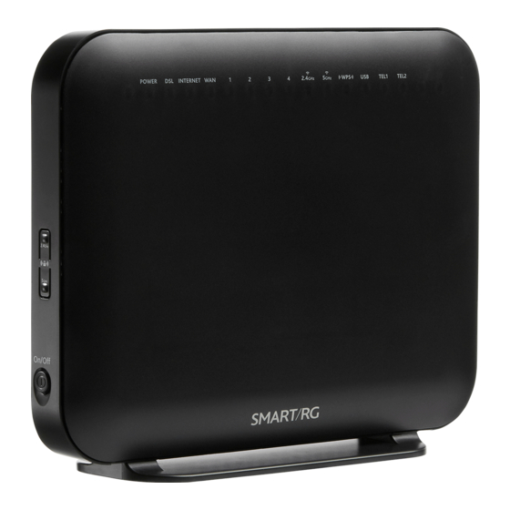
Page 5: Getting Familiar With Your Gateway
This section contains a quick description of the gateway's lights, ports, and buttons to help you get familiar with the model. LED Status Indicators The indicator lights (LEDs) on the front of the SR616ac gateway can help you understand the state of your gateway. -
Page 6: External Buttons
Feature Description Left side On/Off Power switch. 5GHz Enables or disables the 5GHZ wireless function. 2.4GHz Enables or disables the 5GHZ wireless function. External Buttons Smart RG gateways provide push-button controls on the exterior for critical features. These buttons provide a convenient way to toggle the Wi-Fi radio on and off or reset the gateway. -
Page 7: Logging In To Your Gateway's Ui
Logging in to your Gateway's UI To configure the SmartRG gateway's settings, access the gateway's embedded UI. 1. Open a Web browser on your computer. 2. In the address field, enter http://192.168.1.1 (the default IP address of the DSL gateway). The authentication dialog box appears. -
Page 8: Wan
The WAN status screen provides a high level overview of the connection between your Internet Service Provider and your gateway device. The WAN interface can physically be DSL or Ethernet and supports a number of Layer 2 and later configuration options covered later in this document. -
Page 9: Statistics
The fields on this page are defined below. Field Name Description Interface The connection interface (Layer 2 interface) through which the gateway handles the traffic. The service identifier such as pppoe_0_1_1.35. Description The service type. Options are PPPoE , IPoE , and Bridge . Type The VLAN ID. -
Page 10: Wan Service
The fields on this page are defined below. Field Name Description Available LAN interfaces. Options are LAN1 - LAN4 , ETHWAN , 5GHz Band , and 2.4 GHz Band . Interface Received Transmitted & columns Bytes The total number of packets in bytes. Pkts The total quantity of packets. -
Page 11: Xtm
The fields on this page are defined below. Field Name Description Interface Available WAN interfaces. The service description. Options are pppoe , ipoe , and b , followed by the identifier for each service. Description Received Transmitted & columns Bytes The total number of packets in bytes. -
Page 12: Xdsl
xDSL On this page, you can view the DSL statistics for your gateway. All xDSL (VDSL or ADSL) interfaces configured for your gateway are included. The terms and their explanations are derived from the relevant ITU - T standards and referenced accordingly. 1. - Page 13 2. To run an xDSL (BER) test, follow the instructions in "Running xDSL (BER) tests". 3. To reset the counters, click Reset Statistics near the bottom of the page. The fields on this page are defined below. Field Name Description Synchronized Time Time when the last synchronization was performed.
- Page 14 Field Name Description L (# of bits in each data Number of bits included within each data symbol. symbol) D (interleaver depth) Interleaving depth in the current latency path. I (interleaver block size Interleaving block size in the current latency path. in bytes) N (RS codeword size) The number of bits per codeword.
- Page 15 References ITU-T Recommendation G.992.1 (1999), Asymmetric digital subscriber line (ADSL) transceivers ITU-T Recommendation G.992.3 (2005), Asymmetric digital subscriber line transceivers 2 (ADSL2) ITU-T Recommendation G.997.1 (2006), Physical layer management for digital subscriber line (DSL) transceivers ITU-T Recommendation I.432.1 (1999), B-ISDN user-network interface – Physical layer specification: General characteristics Running xDSL (BER) tests 1.
-
Page 16: Route
3. When the test completes, a success dialog box appears. Note: If the Error Ratio reaches e-5, you cannot access the Internet. Route On this page, you can view the LAN and WAN route table information configured in your gateway for both IPv4 and IPv6 implementation. -
Page 17: Arp
The fields on this page are defined below. Field Name Description Destination Destination IP addresses. ( For IPv4 only ) Gateway IP address. Gateway ( For IPv4 only ) Subnet Mask. Subnet Mask ( For IPv6 only ) Identifies the next server in the IPv6 path, if any. Next Hop Flag Status of the flags. -
Page 18: Dhcp
The fields on this page are defined below. Field Name Description IP address IP address of the host. Each entry in the ARP cache is marked with a status flag. Options are Complete , Permanent , and Published . Flags MAC Address MAC address of the host. -
Page 19: Cpu & Memory
CPU & Memory On this page, you can view the CPU and memory data for the gateway. In the left navigation bar, click Device Info > CPU & Memory. The following page appears, showing the current usage and history. The information refreshes automatically. Advanced Setup In this section, you can configure network interfaces, UPnP, quality of service, and other features. - Page 20 2. Modify the settings as needed, using the information in the table below. 3. Click Apply/Save to commit your changes. The new interface appears on the DSL ATM Interface Configuration page. 4. To remove an interface, click the Remove checkbox next to it and then click the Remove button.
- Page 21 Field Name Description Select DSL Latency Select the level of DSL latency. Options are: Path0 (Fast): No error correction and can provide lower latency on error-free lines. This is the default. Path1 (Interleaved): Error checking that provides error-free data which increases latency. Select DSL Link Select the linking protocol.
-
Page 22: Ptm Interface
PTM Interface SmartRG gateway follow VDSL2 standards to support Packet Transfer Mode (PTM). An alternative to ATM mode, PTM transports packets (IP, PPP, Ethernet, MPLS, and others) over DSL links. For more information, refer to the IEEE802.3ah standard for Ethernet in the First Mile (EFM). -
Page 23: Eth Interface
Field Name Description Select Scheduler for Queues Select the algorithm used to schedule queue behavior. VC scheduling is different than scheduling of Equal Precedence done for default queues. Options are: Round Robin (weight=1): Packets are accessed in a round robin style and classes can be assigned. -
Page 24: Wan Service
3. To add an entry, click Add. The following page appears. 4. Select the LAN port you want to use as a WAN port. 5. Click Apply/Save to commit your changes. The interface is added to the ETH WAN Interface Configuration page. WAN Service On this page, you can add, remove, or edit a WAN service. -
Page 25: Ppp Over Ethernet Wan Service
4. To add a service, click Add. The following page appears. 5. Configure the settings as desired, using the information in the topics listed below: "PPP over Ethernet WAN Service" "IP over Ethernet WAN Service" "Bridging" PPP over Ethernet WAN Service There are several parts to configuring a PPP over Ethernet (PPPoE) WAN service. - Page 26 1. In the left navigation bar, click Advanced Setup > WAN Service and then click Add. The following page appears. 2. Select the Layer 2 interface to use for the WAN service. SMARTRG INC. PROPRIETARY AND CONFIDENTIAL. ALL RIGHTS RESERVED. COPYRIGHT © 2018...
- Page 27 3. Click Next. The following page appears. 4. In the WAN Service Type field, accept the default of PPP over Ethernet (PPPoE). 5. (Optional) Modify the other fields, using the information in the following table. Field Name Description Enter Service Description (Optional) Enter a name to describe this configuration. Enter 802.1P Priority Enter the priority for this service.
- Page 28 Field Name Description Network Protocol Different scheduling priorities can be applied to statistically multiplexed data flows. Selection Since each data flow has its own queue, an ill-behaved flow (which has sent larger packets or more packets per second than the others) will only punish itself and not other sessions.
- Page 29 SMARTRG INC. PROPRIETARY AND CONFIDENTIAL. ALL RIGHTS RESERVED. COPYRIGHT © 2018...
- Page 30 7. Modify the fields as needed, using the information in the table provided below. Field Name Description PPP Username and Password section PPP Username Enter the username required for authentication to the PPP server. Use base MAC address as Click this checkbox to use the base MAC address of the gateway as the PPP user name. username PPP Password Enter the password required for authentication to the PPP server.
- Page 31 Field Name Description Enable MAC Clone Click to enable MAC cloning. Additional fields appear. Options are: To use a specific MAC address, enter the MAC address that you want to clone. To use the MAC address of the connected PC, click Clone this PC's MAC Address.
- Page 32 Field Name Description Enable IGMP Multicast Click to enable this service to act as an IGMP multicast source. Source MLD Multicast section Enable MLD Multicast (Available only for IPv6 environments) Click to enable MLD multicast. Used by IPv4 hosts Proxy to report multicast group memberships to any neighboring multicast routers.
- Page 33 11. Click Next. The following page appears where you will select DNS Server settings. 12. Do one of the following to configure the DNS: Select the DNS server interface: Select interface entries and click the arrows to move the entries right or left.
-
Page 34: Ip Over Ethernet Wan Service
Define a static IPv6 DNS IP address: Click Use the following Static IPv6 DNS address and enter the DNS server IP addresses. 13. Click Next. The summary page appears indicating that your PPPoE WAN setup is complete. 14. Review the summary and either click Apply/Save to commit your changes or click Back... - Page 35 1. In the left navigation bar, click Advanced Setup > WAN Service and then click Add. The following page appears. 2. Select an ATM interface to use for the WAN service and click Next. The following page appears. 3. Select IP over Ethernet.
- Page 36 4. Modify the other fields as needed, using the information in the following table. Field Name Description Enter Service (Optional) Enter a name to describe this configuration. Description Enter 802.1P Options are 0 - 7. The default is -1 (disabled). Priority For tagged service, enter values in this field and the 802.1Q VLAN ID...
- Page 37 5. Click Next. The following page appears. SMARTRG INC. PROPRIETARY AND CONFIDENTIAL. ALL RIGHTS RESERVED. COPYRIGHT © 2018...
- Page 38 6. Enter the relevant WAN IP Settings, using the information provided in the table below. Field Name Description Obtain an IP address This option is selected by default. DHCP is enabled in MER mode. Click to prevent automatically the ISP automatically assigning the WAN IP to the gateway. Option 50 Request IP Address Enter the IP address to be used when sending messages.
- Page 39 Field Name Description Dhcpv6 Address Assignment Select this option for the CPE to receive the WAN IP from the ISP. (IANA) Dhcpv6 Prefix Delegation (IAPD) This option is selected by default. The CPE generates the WAN IP's prefix from the server's REST by MAC address.
- Page 40 gateway to access the Internet normally, you need to add a route on the uplink equipment. Failure to do so will cause access to the Internet to fail. The fields on this page are defined below. FIELD NAME DESCRIPTION Enable NAT This option is selected by default.
- Page 41 9. Click Next. The following page appears. 10. Select a WAN interface to act as the system default gateway or accept the default interface. 11. (Optional) For IPv6 environments, in the Selected WAN Interface field, select the preferred WAN interface for the default IPv6 gateway.
- Page 42 12. Click Next. The following page appears. 13. Modify the settings as needed. SMARTRG INC. PROPRIETARY AND CONFIDENTIAL. ALL RIGHTS RESERVED. COPYRIGHT © 2018...
-
Page 43: Bridging
14. Click Next. The following page appears. 15. Review the IPoE settings. You can modify the settings by clicking the Back button. 16. Click Apply/Save to save and apply the settings. Bridging Before you can configure a bridge WAN service, you must create the related Layer2 ATM interface. SMARTRG INC. - Page 44 1. In the left navigation bar, click Advanced Setup > WAN Service and then click Add. The following page appears. 2. Select the interface for the WAN service and then click Next. The following page appears. SMARTRG INC. PROPRIETARY AND CONFIDENTIAL. ALL RIGHTS RESERVED. COPYRIGHT © 2018...
- Page 45 3. Select Bridging. Multicast source fields appear. 4. Modify the other fields as needed, using the information in the following table. Field Name Description Allow as IGMP Multicast Select to enable this service to act as an IGMP multicast source. Source Allow as MLD Multicast Source Select to enable this service to act as an MLD multicast source.
-
Page 46: Vpn
In this section, you can configure tunneling protocols (L2TP or PPTP clients) for your network. L2TP Client Configuration On this page, you can configure the L2TP (Layer 2 Tunneling Protocol) client. 1. In the left navigation menu, click Advanced Setup > and then click Add. - Page 47 Field Name Description Enable Firewall (SPI) (Optional) Click to enable the firewall. Enable Click to enable this L2TP client configuration. 3. Click Next. The following page appears. 4. Select the default gateway by selecting interface entries and clicking the arrows to move the entries right or left.
- Page 48 5. Click Next. The following page appears. 6. Do one of the following to configure the DNS server: Select the DNS server interface: Select interface entries and clicking the arrows to move the entries right or left. Define a static DNS IP address: Click Use the following Static DNS IP address and enter the DNS server IP addresses.
-
Page 49: Pptp Client
7. Click Next. The summary page appears. 8. Click Apply / Save to implement your settings. PPTP Client On this page, you can configure the PPTP (Point-to-Point Tunneling Protocol) client. 1. In the left navigation menu, click Advanced Setup > >... - Page 50 2. Fill in the fields, using the information in the table below. The Description, Interface, and PPTP Server IP/Domain fields are required. Field Name Description Description Enter a useful description of this configuration. WAN Interface Select the WAN interface for this client. PPTP Server IP/Domain Enter the IP address of the PPTP server.
- Page 51 3. Click Next. The following page appears. 4. Select the default gateway by selecting interface entries and clicking the arrows to move the entries right or left. SMARTRG INC. PROPRIETARY AND CONFIDENTIAL. ALL RIGHTS RESERVED. COPYRIGHT © 2018...
- Page 52 5. Click Next. The following page appears. 6. Do one of the following to configure the DNS server: Select the DNS server interface: Select interface entries and clicking the arrows to move the entries right or left. Define a static IP address: Click Use the following Static DNS IP address and enter the DNS server IP addresses.
-
Page 53: Ethernet Config
7. Click Next. The summary page appears. 8. Click Apply / Save to implement your settings. Ethernet Config On this page, you can configure the Ethernet speed for your gateway. SMARTRG INC. PROPRIETARY AND CONFIDENTIAL. ALL RIGHTS RESERVED. COPYRIGHT © 2018... -
Page 54: Lan
1. In the left navigation menu, click Advanced Setup > Ethernet Mode. The following page appears. 2. To set a specific speed, select it in the Configure field. Options are Auto, 100 Full, 100 Half, 10 Full, and 10 Half. The default is Auto. 3. - Page 55 1. In the left navigation menu, click Advanced Setup > LAN. The following page appears. 2. (Optional) In the GroupName field, select the interface group for this configuration. If no groups are defined, the only option is Default. 3. Modify the other fields using the information in the following table. The default configuration settings work for most scenarios.
- Page 56 Field Description IP Address / (Optional) Modify the IP address and subnet mask of the device. The default IP address is Subnet Mask that of the gateway and the subnet mask is 255.255.255.0. Enable IGMP Snooping This option is enabled by default. To disable this option, click the checkbox to clear it. Options are Standard Mode and Blocking Mode.
- Page 57 5. To add addresses to the Static IP Lease List: a. Click Add Entries below the MAC Address table. The DHCP Static IP Lease page appears. b. Enter the MAC address of the LAN host. c. Enter the static IP address that is reserved for the host. d.
-
Page 58: Ipv4 Autoconfig
11. Click Apply/Save to apply your settings. IPv4 Autoconfig 1. In the left navigation menu, click Advanced Setup > LAN. The following page appears. You can also reach this page by clicking Advanced Setup > > IPv4 Autoconfig in the left menu. SMARTRG INC. - Page 59 2. (Optional) In the GroupName field, select the interface group for this configuration. If there are no groupings defined, the only option is Default. 3. Modify the other fields using the information in the following table. The default configuration settings work for most scenarios.
- Page 60 b. Click the State checkboxes as needed to manage DHCP for each LAN interface in the table, and then click Advanced Setup > > IPv4 Autoconfig in the left menu. 5. To add addresses to the Static IP Lease List: a.
-
Page 61: Ipv6 Autoconfig
10. Click Apply/Save to apply your settings. IPv6 Autoconfig On this page, you can configure your gateway's IPv6 environment. 1. In the left navigation bar, click Advanced Setup > > IPv6 Autoconfig. The following page appears. 2. To enable advertisement of the ULA prefix, click Enable ULA Prefix Advertisement. - Page 62 Field Name Description Static LAN IPv6 Address Enter the interface address in IPv6 format (including the prefix length). This address must begin Configuration with "fd". The prefix length must be "64". The address and prefix must reside on the same network.
-
Page 63: Local Vlan Setting
Field Name Description ( Optional ) This option enables LAN-to-LAN Multicast until the first WAN service is connected. Enable MLD LAN to LAN Options are Disable and Enable . The default is Disable . Multicast Enable Relay Click to enable the relay function. Additional fields appear. Do the following: 1. -
Page 64: Nat
4. To add a VLAN: a. Click Add. A table appears where you can enter the details. b. Enter the VLAN ID. Options are 1 - 4094. c. In the Pbits field, enter the type of bits being passed. Options are 1 - 7. 5. - Page 65 1. In the left navigation bar, click Advanced Setup > NAT. The following page appears. SMARTRG INC. PROPRIETARY AND CONFIDENTIAL. ALL RIGHTS RESERVED. COPYRIGHT © 2018...
- Page 66 2. To add a virtual server: a. Click Add. The following page appears. b. Modify the fields as needed, using the information in the table below. Field Description Use Interface Select the interface that you want to configure. SMARTRG INC. PROPRIETARY AND CONFIDENTIAL. ALL RIGHTS RESERVED. COPYRIGHT © 2018...
-
Page 67: Port Triggering
Field Description Service Name Select or enter the service for which you want to forward IP packets. Options are: Select a Service: Select from services defined for your network. The port table at the bottom of the page is updated with the default port ID defined for the service. - Page 68 1. In the left navigation bar, click Advanced Setup > > Port Triggering. The following page appears. SMARTRG INC. PROPRIETARY AND CONFIDENTIAL. ALL RIGHTS RESERVED. COPYRIGHT © 2018...
- Page 69 2. To add a port trigger, click Add. The following page appears. 3. Modify the fields as needed, using the information in the following table. 4. To remove a trigger, click the Remove check box next to it and then click the Remove button.
-
Page 70: Dmz Host
Field Name Description Enter the starting and ending numbers of the range of available outgoing trigger ports. Options are 1 - Trigger Port Start 65535 . Trigger Port End Note: You can use a single port number, several port numbers separated by commas, port blocks consisting of two port numbers separated by a dash, or any combination of these, for example 80, 90-140, 180. -
Page 71: Alg
On this page, you can enable Session Initiation Protocol (SIP) for your NAT. SIP is a communications protocol for signaling and controlling multimedia communication sessions. 1. In the left navigation bar, click Advanced Setup > > ALG. The following page appears. 2. -
Page 72: Security
1. In the left navigation bar, click Advanced Setup > > Multi NAT and then click Add. The following page appears. 2. Modify the fields as needed, using the information in the table below. Field Description Rule Type Select the type of rule. Options are One to One, One to Many, Many to One, and Many to Many. - Page 73 1. In the left navigation bar, click Advanced Setup > Security and then click Add. The following page appears. You can also reach the Outgoing IP Filtering Setup page by clicking Advanced Setup > Security > IP Filtering > Outgoing. 2.
-
Page 74: Ip Filtering - Incoming
Field Name Description Destination IP Enter the destination IP address of a LAN side host for which you wish to filter (block) outgoing traffic using the address [/prefix specified protocol(s). length] Note: The address specified here can be a particular address or a block of IP address on a given network subnet. -
Page 75: Mac Filtering
Field Name Description IP Version For the filter to be configured and effective for IPV6, the gateway must be installed on a network that is either a pure IPV6 network (with that protocol enabled) or is both IPV4 and IPV6 dual protocol enabled/configured. - Page 76 1. In the left navigation bar, click Advanced Setup > Security > Filtering. The following page appears. 2. To modify settings for an existing policy, click the Change checkbox next to it, and then click Change Policy. Options are BLOCKED and FORWARD. The page refreshes, showing that the action has changed. The Change Policy button acts like a toggle switch, clicking it switches the policy from BLOCKED to FORWARD and back again.
-
Page 77: Parental Control
1. On the MAC Filtering Setup page, click Add. The following page appears. 2. Fill in the fields, using the information provided in the following table. The Protocol Type field is required. 3. Click Apply/Save to commit your changes. Field Name Description Select the protocol associated with the device at the destination MAC address. - Page 78 1. In the left navigation menu, click Advanced Setup > Parental Control and then click Add. The following page appears. 2. Enter the user name for which this rule applies. 3. (Optional) Enter an additional MAC address by clicking Other MAC Address and entering the address in the adjacent field.
-
Page 79: Url Filter
Url Filter On this page, you can prevent the LAN users from accessing some Web sites. 1. Click Advanced Setup > Parental Control > Filter. The following page appears. 2. Select whether to exclude or include the URLs in the list you are going to create. If you select Exclude, users cannot access the URLs in the list. -
Page 80: Quality Of Service
Quality of Service Quality of Service (QoS) enables prioritization of Internet content to help ensure the best possible performance. This is particularly useful for streaming video and audio content with minimized potential for drop-outs. QoS becomes significant when the sum of all traffic (audio, video, data) exceeds the capacity of the line. -
Page 81: Qos Queue
QoS Queue On this page, you can configure a queue and add it to a selected Layer2 interface. You can also edit and delete queues. A number of standard queues are already defined. You may have to remove queues that you don't need in order to create the desired queues. 1. - Page 82 queue precedence selections. In most cases, you can use the default values. c. Click Apply/Save. You are returned to the Qos Queue Setup page. 3. To remove a queue, click the Remove checkbox to the right of the entry and then click the Remove button at the bottom of the page.
-
Page 83: Qos Classification
In the left navigation bar, click Advanced Setup > Quality Of Service > QoS Queue > Wlan Queue. The following page appears. QoS Classification On this page, you can create classifications (traffic class rules) for assigning ingress traffic to a priority queue. 1. - Page 84 2. Fill in the fields, using the information in the table below. 3. Click Apply/Save to commit your changes. The fields on this page are defined below. Field Name Description Add Network Traffic Class Rule section Traffic Class Name Enter a descriptive name for this rule. This option is set to Last and cannot be changed.
-
Page 85: Qos Port Shaping
Field Name Description Select an interface for incoming traffic. Options are LAN , WAN , Local , 2.4GHz, 5GHz, and any Ingress Interface interface defined for your network. The default is LAN . Select the Ethernet interface type for this classification. Options include IP , ARP , IPV6 , PPPoE , and Ether Type any other Ethernet interface defined for your network. -
Page 86: Routing
2. (Optional) For each interface in the table, enter a Shaping Rate (in Kbps) and a Burst Size (in bytes). The default settings work for most scenarios. 3. Click Apply/Save to commit your changes. Routing In this section, you can configure default gateway, static routing, policy routing and RIP settings. Default Gateway On this page, you can select the WAN interface for the default gateway. -
Page 87: Static Route
1. In the left navigation bar, click Advanced Setup > Routing. The following page appears. 2. (Optional) Select entries in the lists and click the arrows to move your selections from left to right or right to left. 3. (Optional) In the Selected WAN Interface field, select the appropriate interface. -
Page 88: Policy Routing
2. Fill in the fields, using the information in the table below. 3. Click Apply/Save to commit your changes. Field Name Description Select the IP version associated with the static route you wish to create. Options are IPv4 and IPv6 . The IP Version default is IPv4 . -
Page 89: Rip
2. Fill in the fields, using the information in the table below. 3. Click Apply/Save to commit your changes. You are returned to the Policy Routing Setting page. 4. To remove a route, click the Remove check box next to it and then click the Remove button. -
Page 90: Dns
1. In the left navigation bar, click Advanced Setup > Routing > RIP. The following page appears. 2. For the interface that you want to modify, select values using the information in the table below. 3. To enable a configuration, click the Enabled checkbox next to the interface. - Page 91 1. In the left navigation bar, click Advanced Setup > DNS. The following page appears. 2. Do one of the following to configure the DNS server: Select the DNS server interface from available WAN interfaces: Select interface entries in the lists and click the arrows to move the entries right or left.
-
Page 92: Dynamic Dns
Define a static IPv6 DNS IP address: Click Use the following Static IPv6 DNS address and enter the DNS server IP addresses. 3. Click Apply/Save to apply your settings. Dynamic DNS Dynamic DNS (DDNS) automatically updates a name server in the DNS with the active DNS configuration of its configured hostnames, addresses or other data. -
Page 93: Dsl
1. In the left navigation bar, click Advanced Setup > > Config. The following page appears. 2. To add a DNS domain, click Add. The following page appears. 3. Enter a domain name and IP address for the domain. Only letters, numbers, dashes, and periods are allowed. 4. - Page 94 1. In the left navigation menu, select Advanced Setup > DSL. The following page appears. SMARTRG INC. PROPRIETARY AND CONFIDENTIAL. ALL RIGHTS RESERVED. COPYRIGHT © 2018...
- Page 95 SMARTRG INC. PROPRIETARY AND CONFIDENTIAL. ALL RIGHTS RESERVED. COPYRIGHT © 2018...
-
Page 96: Upnp
2. Modify the settings as needed. 3. (Optional) To modify additional parameters, click Advanced Settings. The following page appears. 4. Select the test mode that you want to run. 5. To view the tone selection table, click Tone Selection. Changing these settings arbitrarily is not recommended. Close the window to return to the DSL Advanced Settings page. -
Page 97: Dns Proxy
1. In the left navigation menu, click Advanced Setup > UPnP. The following page appears. 2. To disable UPnP, click the Enable UPnP check box to clear it. 3. Click Apply/Save to save and apply the settings. DNS Proxy On this page, you can enable or disable the DNS proxy function. This function is enabled by default. 1. -
Page 98: Interface Grouping
Interface Grouping On this page, you can configure interface groupings. Interface grouping supports multiple ports to PVC and bridging groups. Each group performs as an independent network. Only the default group has an IP interface. To support this feature, you must create mapping groups with the appropriate LAN and WAN interfaces. -
Page 99: Ip Tunnel
2. To add a new grouping, click Add. The following page appears. 3. Follow the on-screen instructions and then click Apply/Save. 4. To remove a grouping from the list, click the Remove checkbox next to the group name and then click the Remove button. -
Page 100: Ipv6Inipv4
In this section, you can configure connections of IPv6 networks across the IPv4 internet or IPv4 in IPv6. IPv6inIPv4 On this page, you can configure a tunnel for IPv6inIPv4. 1. In the left navigation bar, click Advanced Setup > IP Tunnel and then click Add. -
Page 101: Certificate
2. Enter a Tunnel Name. In the Mechanism field, the only option is DS-Lite. 3. Select the interfaces associated with the tunnel you wish to establish. 4. In the AFTR (Address Family Transition Router) field, do either of the following: To configure manually, enter the remote address in the AFTR field. - Page 102 Creating certificate requests 1. In the left navigation bar, click Advanced Setup > Certificate. The following page appears. 2. Click Create Certificate Request. The following page appears. 3. Enter your connection details, using the information provided in the table below. 4.
- Page 103 Field Name Description Common Name Enter the IP address (in dotted decimal notation), domain name, or email address. Browsers use this information to verify your certificate is valid. Organization Name Enter the name or the company or organization creating the request. State/Province Enter the full name of the state or province where your organization's head office is located.
-
Page 104: Trusted Ca
4. Paste the Private Key information between the BEGIN markers. 5. Click Apply to commit this certificate. Trusted CA On this page, you can import Trusted Certificates to identity other gateways to your gateway as a trusted source. 1. In the left navigation bar, click Advanced Setup >... -
Page 105: Power Management
3. In the Certificate Name field, type a descriptive name for this certificate. If you are using this certificate with TR-069, the name must be "acscert". 4. Paste the certificate details between the BEGIN markers. 5. Click Apply to commit this certificate. After you add one certificate, a Remove button appears on the... - Page 106 2. Fill in the fields, using the information in the table below. The fields provided for the IGMP and MLD configurations are largely the same. 3. To create or remove exceptions in the Group Exception List table, follow the instructions in "Managing group exception lists".
-
Page 107: Managing Group Exception Lists
Managing group exception lists You can manage exceptions for multicast groups using the IGMP Group Exception List MLD Group Exception List tables. The first two entries are created by default; you cannot change these entries. To add an exception, type the IP address in the Group Address field, enter the mask information in the Mask / Mask bits... -
Page 108: Wireless
Wireless In this section, you can configure the wireless interface settings for your gateway, including basic and advanced settings, MAC filtering, and wireless bridging. Basic On this page, you can configure basic features of the WiFi LAN interface. You can enable or disable the WiFi LAN interface, hide the network from active scans, set the WiFi network name (also known as SSID) and restrict the channel set based on country requirements. - Page 109 2. If you want to view or configure the 2.4GHz band settings, click 2.4 GHZ Band in the left menu. 3. Modify the settings as desired, using the information provided in the table below. 4. (Optional) Define up to three virtual access points for guest access using the information from the Wireless - Guest/Virtual Access Points section of the table below.
-
Page 110: Security
Security On this page, you can configure network security settings of a wireless LAN interface, either by using the WiFi Protected Setup (WPS) method or by setting the network authentication mode. For WiFi Protected Setup, the following methods are supported: PIN entry: Mandatory method of setup for all WPS-certified devices. - Page 111 1. In the left navigation bar, click Wireless > 5 GHz Band 2.4 GHz Band > Security. The following page appears. 2. Modify the settings as needed, using the information provided in the field description table below and in the sections that explain each authentication method.
-
Page 112: Open And Shared Authentication
Field Name Description Add Client (Available for WPA-PSK, WPA2-PSK and Open Network Authentication methods) Select the method for generating the WPS PIN. Options are: Enter STA PIN: Type the input station PIN for the client in the field below the radio button. -
Page 113: 802.1X Authentication
Modify the fields as needed and then click Apply/Save. Field Name Description Select the Wired Equivalent Privacy (WEP) mode. Options are Enabled and Disabled . The default is WEP Encryption Disabled for Open authentication and Enabled for Shared authentication. Select the length of the encryption method. Options are 128-bit and 64-bit . 128-bit is the default and is Encryption Strength the more robust option for security. -
Page 114: Wpa2 And Mixed Wpa2/Wpa Authentication
Modify the fields as needed, using the information provided in the table below, and then click Apply/Save. Field Name Description RADIUS Server IP Enter the IP address of the RADIUS (Remote Authentication Dial In User Service) server associated with address your network. - Page 115 Modify the fields as needed, using the information provided in the table below, and then click Apply/Save. Field Name Description Select whether management frames are protected. Options are Disabled , Capable , and Required . The Protected Management default is Disabled . Frames WPA2 Preauthentication Select whether clients can pre-authenticate with the gateway while still connected to another AP.
-
Page 116: Wpa2-Psk And Mixed Wpa2/Wpa-Psk Authentication
Field Name Description WPA /WAPI Encryption Select the encryption standard. This field is displays the option most compatible with the selected network authentication method. Options are: AES: Advanced Encryption Standard. This is the default. TKIP+AES: AES combined with TKIP (Temporary Key Integrity Protocol) allows access by either standard. -
Page 117: Mac Filter
MAC Filter On this page, you can configure whether wireless clients are allowed to access the wireless network of the wireless gateway. 1. In the left navigation bar, click Wireless > Filter. The following page appears. 2. In the Select SSID field, select the access point that you want to configure. -
Page 118: Wireless Bridge
c. Click Apply/Save to save the address to the list. You are returned to the Wireless - MAC Filter landing page. 5. To remove a MAC address from the list, click the Remove check box next to it and then click the Remove button. -
Page 119: Advanced
2. Modify the fields as needed, using the information provided in the table below. Field Name Description AP Mode Select whether to enable or disable access point (AP) functionality. Options are: Wireless Bridge: Disables AP functionality. Access Point: Enables AP functionality. Wireless bridge functionality is still available and wireless stations can associate to the AP. - Page 120 1. In the left navigation bar, click Wireless > Advanced. The following page appears. 2. Modify the fields as needed, using the information in the following table. 3. Click Apply/Save to commit your changes. Field Name Description Band The only option for this field is the band selected in the left menu. SMARTRG INC.
- Page 121 Field Name Description Channel Select the Wi-Fi channel you want to use. The current channel number displays to the right of the field. For the 5GHz band, options are Auto and 36 through 157 . For the 2.4GHz band, options are Auto and 1 - 7 .
- Page 122 Field Name Description Multicast rate Select the multicast transmission rate for the network according to the speed of your wireless network. Select from a range of transmission speeds or select Auto to have the gateway automatically use the Auto-Fallback fastest possible data rate and enable the feature.
-
Page 123: Station Info
Field Name Description WMM No The acknowledge policy used at the MAC level. Enabling this option allows better throughput but, in a noisy RF environment, higher -963 error rates may result. The default is Disabled , meaning that an Acknowledgment acknowledgment packet is returned for every packet received. - Page 124 1. In the left navigation menu, click Wireless > Wifi Insight. The following page appears. You can also reach this page by clicking Wireless > Wifi Insight > Configure. 2. In the Sample Interval section, select the number of seconds for sampling to occur. Options are 5, 10, 15, and 20 seconds.
-
Page 125: Site Survey
4. In the Database Size section, configure the database size limits: a. In the Database Size field, enter the maximum size for the database file where the collected data will be stored. The default is 2 MB. b. (Optional) Select whether to stop data collection when the maximum size is reached. Options are Overwrite Older Data and Stop Datacollection. -
Page 126: Channel Statistics
2. In the first field above the chart, select the wireless network that you want to review. 3. In the Select Channel field, select the channel that you want to review. 4. In the Select Bandwidth field, select the bandwidth. 5. - Page 127 SMARTRG INC. PROPRIETARY AND CONFIDENTIAL. ALL RIGHTS RESERVED. COPYRIGHT © 2018...
-
Page 128: Voice
Voice In this section, you can view status, enable features, and configure settings for VoIP. VoIP Status On this page, you can view status data for your SIP accounts. In the left navigation menu, click Voice. The following page appears. In the Registration Status field, Up means registered successfully, Down means unregistered, Disabled means the account is not... - Page 129 1. In the left navigation menu, click Voice > SIP Basic Setting. The following page appears. 2. Modify the fields as needed, using the information in the following table. 3. Click Apply to implement your changes. SMARTRG INC. PROPRIETARY AND CONFIDENTIAL. ALL RIGHTS RESERVED. COPYRIGHT © 2018...
- Page 130 The fields on this page are defined below. FIELD NAME DESCRIPTION Select the bound interface name. Options are LAN , Any_WAN , and any other interfaces configured for Bound Interface Name your network. The default is Any_WAN . Country Select the country or region for this voice configuration. Enter the local port of the gateway which is the SIP UA (user agent) port.
-
Page 131: Sip Advanced Setting
FIELD NAME DESCRIPTION Polarity Reverse Enable Enable or disable this function by selecting and clearing the check boxes. Authentication name Enter the user name. Password Enter the password. Cid Name Enter the user name that should display as the caller ID name. Cid Number Enter the number that should display as the caller ID number. - Page 132 In the bottom section are settings for Fax, QoS, caller ID, service offer models and so on. SMARTRG INC. PROPRIETARY AND CONFIDENTIAL. ALL RIGHTS RESERVED. COPYRIGHT © 2018...
- Page 133 2. Modify the fields as needed, using the information provided in the table below. 3. Click Apply to implement the settings. The fields on this page are defined below. FIELD NAME DESCRIPTION Line The VoIP line you want to configure. Call waiting Select to enable call waiting notification.
- Page 134 FIELD NAME DESCRIPTION Enter the number to which you want all incoming calls to be forwarded. Unconditionally Call forwarding number Busy Call forwarding Enter the number to which you want all incoming calls to be forwarded when the line is busy. number No Answer Call Enter the number to which you want all incoming calls to be forwarded when the calls are not answered.
- Page 135 FIELD NAME DESCRIPTION Enter the registration expire timeout. The default is 172800 (48 hours). Registration Expire Timeout Enter the time interval for closing a conversation. The default is 86400 (24 hours). Session Expire Time Enter the minimum interval for closing a conversation. This value must be 90 seconds or greater. Min Session Expire Time Digitmap Setting section...
-
Page 136: Sip Star Code Setting
SIP Star Code Setting On this page, you can set the numbers that are used with the * key to enable and disable various features. 1. In the left navigation menu, click Voice > SIP Star Code Setting. The following page appears. 2. - Page 137 1. In the left navigation menu, click Voice > SIP Extra Setting. The following page appears. 2. Modify the fields as needed, using the information in the table below. 3. Click Apply to implement the settings. The fields on this page are defined below. Field Description Line...
-
Page 138: Sip Debug Setting
SIP Debug Setting On this page, you can configure the debugging settings. 1. In the left navigation menu, click Voice > SIP Debug Setting. The following page appears. 2. Modify the fields as needed, using the information in the table below. 3. - Page 139 Field Description ( Optional ) Select the level of detail stored in the System log. Options are SPY_GEN_INFO , SPY_FNENTER , System Log Level SPY_EVENT , SPY_MINOR_ERR , SPY_MAJOR_ERR , SPY_FATAL_ERR , and SPY_LEVEL_OFF . The default is SPY_EVENT . ( Optional ) Select the level of detail stored in these logs.
-
Page 140: Sip Black Filter
SIP Black Filter On this page, you can configure the black filtering settings. 1. In the left navigation menu, click Voice > SIP Black Filter. The following page appears. 2. In the black list column, enter the phone number that you want to block. 3. -
Page 141: Diagnostics
Diagnostics Line performance diagnostic tools are supported by your SmartRG gateway. Three legs of the data path are included in the available tests: LAN connectivity, DSL connectivity, and Internet connectivity tests. Diagnostics On this page, you can test the connection to your local network, the connection to your DSL service provider, and the connection to your Internet service provider. -
Page 142: Ethernet Oam
3. To test another connection, click Next Connection. The data refreshes and the Previous Connection button appears. 4. If a test fails, click the Help link located in the last column to learn more about what is being tested and what actions you can take. - Page 143 2. To enable Ethernet Link OAM (802.3ah): a. Click the Enabled checkbox. Additional fields appear. b. Modify the fields as needed, using the information in the Ethernet Link OAM (802.3ah) section of the table below. 3. To enable Ethernet Service OAM (802.1ag/Y.1731): a.
- Page 144 b. Modify the fields, using the information provided in the Ethernet Service OAM (802.1ag/Y.1731) section of the table below. 4. Click Apply/Save to commit your changes. 5. To run a loopback test, enter a MAC address in the Target MAC field and click Send Loopback at the bottom of the...
-
Page 145: Diagnostic Tools
Field Name Description Click to enable reporting of critical conditions that may cause link failure. Link Events Click to enable on-demand link diagnostics, including bit-error-rate approximation. Remote Loopback Click to enable this feature. Active Mode Ethernet Service OAM (802.1ag/Y.1731) section WAN Interface Select the WAN interface that you want to test. - Page 146 1. In the left navigation menu, click Diagnostics Tools > Ping. The following page appears. 2. Enter the host name or IP address. 3. Click Submit. The details of the ping appear on the page. 4. To return to the Ping Diagnostic page, click Back. 5.
-
Page 147: Traceroute
Traceroute On this page, you can use the Traceroute utility to trace a connection. 1. In the left navigation menu, click Diagnostics Tools > Traceroute. The following page appears. 2. Enter the host name or IP address. SMARTRG INC. PROPRIETARY AND CONFIDENTIAL. ALL RIGHTS RESERVED. COPYRIGHT © 2018... -
Page 148: Start / Stop Dsl
3. Click Submit. The details of the trace appear on the page. 4. To return to the Traceroute Diagnostic page, click Back. 5. To stop a test, click Stop. Start / Stop DSL On this page, you can start or stop your DSL connection. 1. -
Page 149: Management
Management In this section, you can configure server and system log settings, control access, and configure clients. Settings In this section, you can back up the current settings, restore saved settings, or reset the gateway to default settings. Backup On this page, you can back up the current settings for your gateway in a file stored on your computer. 1. -
Page 150: Update
Update On this page, you can restore previously backed-up gateway settings. 1. In the left navigation bar, click Management > Settings > Update. The following page appears. 2. To update settings from a file that you saved previously: a. Click the appropriate Browse button to locate either a customized setting file or the default setting file (.conf file) on your local system and click Open. -
Page 151: Restore Default
Restore Default On this page, you can restore the gateway to the factory default settings. If you think you might need to reload the current settings, create a backup (on the Management > Settings > Backup page) before proceeding. 1. In the left navigation menu, click Management >... - Page 152 2. To view the system log details: a. Click View System Log. The log appears in a separate window. b. To update the data, click Refresh. SMARTRG INC. PROPRIETARY AND CONFIDENTIAL. ALL RIGHTS RESERVED. COPYRIGHT © 2018...
- Page 153 3. To configure the log settings: a. Click Configure System Log. The following page appears. b. Modify the fields as needed, using the information in the table below. c. Click Apply/Save to save and apply your changes. You are returned to the System Log page. The fields on this page are defined below.
-
Page 154: Security Log
Security Log The security log contains a history of events related to sensitive access to the gateway. Logged events include: Password change success / failure Authorized login success / failure Authorized user logged out Security lockout added / removed Authorized / unauthorized resource access Software update 1. -
Page 155: Snmp Agent
SNMP Agent On this page, you can configure the SNMP (Simple Network Management Protocol) settings to retrieve statistics from the SNMP agent for the gateway. You can enable or disable the SNMP agent and set parameters such as the read community, system name and trap manager IP. -
Page 156: Management Server
Management Server SmartRG gateways support TR-069 based standards for remote management, including STUN server configuration. In this section, you can configure the gateway with details about the management ACS (Auto Configuration Server) to which this gateway will be linked. TR-069 The TR-069 client screen contains default connection parameters and generally only needs to be enabled, pointed to the ACS URL, and any required ACS Username and ACS Password entered. - Page 157 Field Name Description ACS URL from DHCP Click to enable the gateway to obtain the ACS URL from the DHCP server. OUI-Serial Select whether to use the MAC address or the device serial number as the identifier. The default is MAC. Inform Select whether to disable or enable the inform feature.
-
Page 158: Stun Config
4. To force the gateway to attempt to sync with the ACS, click the GetRPCMethods button. This will assist you in verifying the TR-069 parameters entered above. 5. Click Apply/Save to commit your changes. STUN Config STUN stands for “Simple Traversal of UDP through NATs”. STUN enables a device to find out its public IP address and the type of NAT service it is sitting behind. - Page 159 2. To view the required STUN settings, click STUN Server Support. Additional fields appear. 3. Modify the fields using the information provided in the following table. 4. Click Save/Apply to commit your changes. Field Name Description STUN Server Address Enter the physical STUN server’s assigned network address. An invalid address will produce an immediate on-page error message from the gateway.
-
Page 160: Xmpp Connection
With these NAT schemes, the initial network address translation may not be used after a specified elapsed time. Internal mapping is dropped. The gateway then assigns a different address mapping. This mechanism allows for coordinated refresh on the bindings for mappings used by the STUN protocol. -
Page 161: Internet Time
2. To add a connection, click Add. The following page appears. 3. In the XMPP Connection field, select whether to use TLS and then click Enable. 4. Modify the fields as needed, using the information provided in the table below. Field Description Username... -
Page 162: Access Control
1. In the left navigation bar, click Management > Internet Time. The following page appears. 2. Click Automatically synchronzie with Internet time servers. Additional fields appear. 3. Select the desired time servers. 4. Select the Time zone offset. 5. (Optional) Click Enable Daylight Savings Time. -
Page 163: Access List
1. In the left navigation bar, click Management > Access Control. The following page appears. 2. Enter the user name in the User Name field. 3. Enter the current password in the Old Password field. 4. Enter the new password in the New Password Confirm Password fields. -
Page 164: Services Control
1. In the left navigation bar, click Management > Access Control > Access List. The following page appears. 2. To enable the listed IP addresses to access local management services, in the Access Control Mode field, click Enable. 3. To add an access list: a. -
Page 165: User Profile
1. In the left navigation bar, click Management > Access Control > Services Control. The following page appears. 2. Select or clear the enable checkbox next to each service and interface that you want to change. 3. (Optional) In the WAN Port Number field, modify the port numbers for the services. -
Page 166: Update Software
1. In the left navigation bar, click Management > Access Control > Logout Timer. The following page appears. 2. In the Logout Timer Period field, type the number of minutes after which a session will be ended. Options are 0 - 60 minutes. -
Page 167: Reboot
3. Click Update Software. Note: When software update is in progress, do not shut down the gateway. After the software update completes, the gateway automatically reboots. Reboot On this page, you can reboot your gateway without needing physical access to the unit. 1. -
Page 168: Logout
Logout 1. To log out of your gateway, click Logout in the left navigation menu. The Logout page appears. 2. Click the Logout button. A success message appears. SMARTRG INC. PROPRIETARY AND CONFIDENTIAL. ALL RIGHTS RESERVED. COPYRIGHT © 2018... -
Page 169: Appendix: Fcc Statements
Appendix: FCC Statements FCC Interference Statement This device complies with Part 15 of the Federal Communications Commission (FCC) Rules. Operation is subject to the following two conditions: This device may not cause harmful interference. This device must accept any interference received, including interference that may cause undesired operation. This equipment has been tested and found to comply with the limits for a Class B digital device, pursuant to part 15 of the FCC Rules. -
Page 170: Ringer Equivalency Number Statement
This equipment uses the following USOC jacks: RJ-11/RJ45/USB/Power Jacks. A plug and jack used to connect this equipment to the premises wiring and telephone network must comply with the applicable FCC Part 68 rules and requirements adopted by the ACTA. A compliant telephone cord and modular plug is provided with this product. It is designed to be connected to a compatible modular jack that is also compliant. -
Page 171: 5Ghz
Le dispositif rencontre l'exemption des limites courantes d'évaluation dans la section 2.5 de RSS 102 et la conformité à l'exposition de RSS-102 rf, utilisateurs peut obtenir l'information canadienne sur l'exposition et la conformité de rf. This transmitter must not be co-located or operating in conjunction with any other antenna or transmitter. This equipment should be installed and operated with a minimum distance of 20 centimeters between the radiator and your body. -
Page 172: Revision History
Revision History Revision Date LAN ports Apr 2018 Updated to match release 2.6.1.5. Mar 2018 Updated to match release 2.6.1 SMARTRG INC. PROPRIETARY AND CONFIDENTIAL. ALL RIGHTS RESERVED. COPYRIGHT © 2018...
Need help?
Do you have a question about the SR616ac and is the answer not in the manual?
Questions and answers