
Related Manuals for SMART/RG SR808ac


Summary of Contents for SMART/RG SR808ac
- Page 1 501 SE Columbia Shores Boulevard, Suite 500 Vancouver, Washington 98661 USA +1 360 859 1780 / smartrg.com / Gateway User Manual Model: SR808ac Release 1.1 April 2018...
-
Page 2: Table Of Contents
Table of Contents Welcome! Wireless Purpose & Scope Radio Intended Audience Primary Network Getting Assistance Guest Network Copyright and Trademarks Appendix: FCC Statements Disclaimer FCC Interference Statement Installing your Gateway FCC Radiation Exposure Statement Getting Familiar with Your Gateway FCC - PART 68 LED Status Indicators Ringer Equivalency Number Statement Connections... -
Page 3: Welcome
Learn more at www.SmartRG.com. Purpose & Scope This Gateway User Manual provides SmartRG customers with installation, configuration and monitoring information for their SR808ac gateway. Intended Audience The information in this document is intended for Network Architects, NOC Administrators, Field Service Technicians and other networking professionals responsible for deploying and managing broadband access networks. -
Page 4: Installing Your Gateway
Installing your Gateway The connectors located on the back of the SR808ac gateway are described below (from top to bottom). 3G USB Data Card / LTE RESET WPS CABLE ON/OFF POWER 1. Connect one end of the supplied cable to the port labeled Cable on the gateway. -
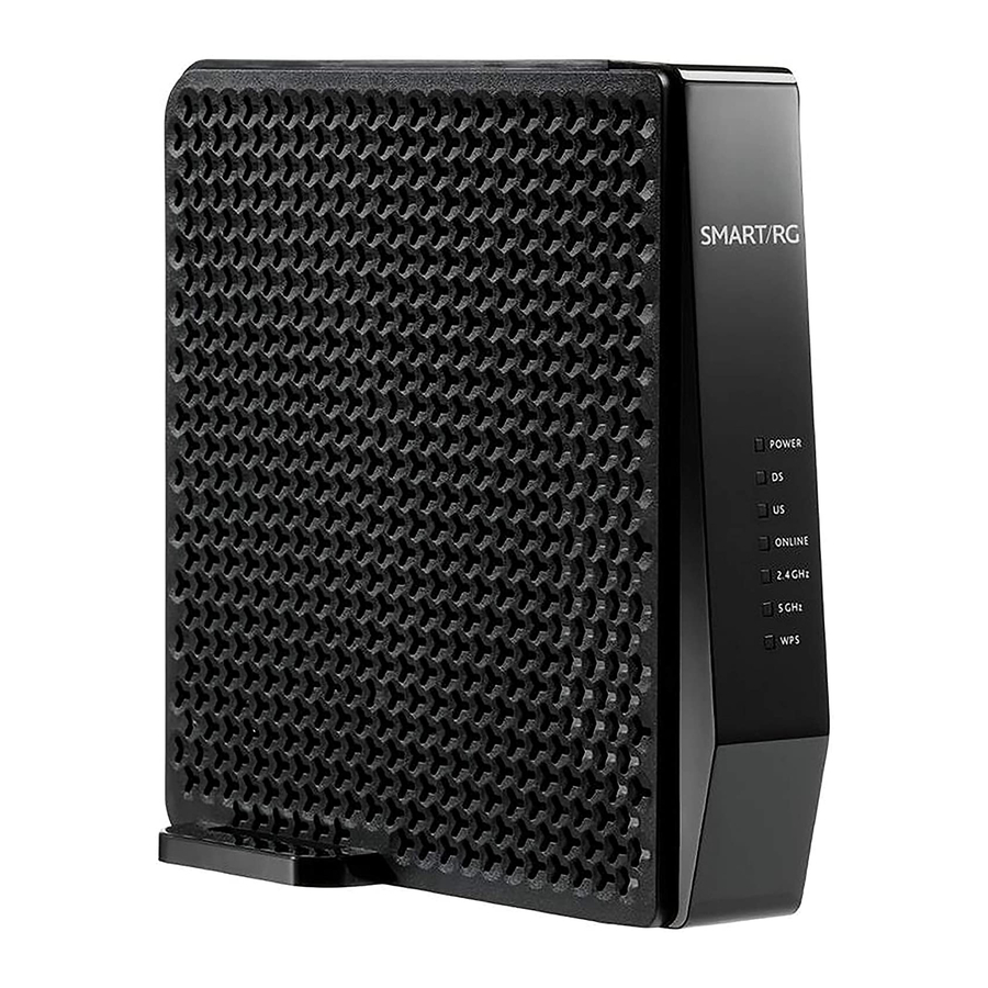
Page 5: Getting Familiar With Your Gateway
Getting Familiar with Your Gateway This section describes the gateway's lights, ports, and buttons to help you get familiar with the SR808ac model. LED Status Indicators Your SmartRG gateway has several indicator lights (LEDs) on its front. The following table describes those LEDs. - Page 6 Interface Description Button for activating WPS. Cable RF cable port, for connecting HFC cable. On/Off On/Off button. Power Power interface, for connecting the power adapter. SMARTRG INC. PROPRIETARY AND CONFIDENTIAL. ALL RIGHTS RESERVED. COPYRIGHT © 2018...
-
Page 7: Logging In To Your Gateway's Interface
Logging in to Your Gateway's Interface To manually configure the SmartRG SR808ac gateway, you must log in to the gateway's embedded UI. 1. Open a Web browser on your computer. 2. Enter http://192.168.0.1 (the default IP address of the cable modem gateway) in the address bar. The login dialog box appears. -
Page 8: Status
Status In this section, you can review status data for software, connections, security, diagnostics, Ethernet speed, and gateway statistics. Software On this page you can view information about the hardware and software versions, MAC address, serial number, system “up” time, and network registration status. -
Page 9: Security
Security On this page, you can change a user's password and restore the factory default settings. 1. In the top navigation bar, click Status and then click Security in the left menu. The Status > Security page appears. 2. To change the security password: a. -
Page 10: Diagnostics
acters or less. d. Click Apply to save your changes. You do NOT have to restore factory defaults to change the password. 3. To restore factory defaults, click and then click Apply. The gateway reboots. 4. To log back into the gateway after the factory defaults are restored, you must enter the factory default user name (admin) and the password found on the Password label on the bottom of the unit. -
Page 11: Ethernet
d. Click Start Test. The Results field is refreshed automatically as the test is performed. The minimum, maximum and average time statistics display in the Results field. Note: You can abort a ping test by clicking Abort Test but you cannot abort a trace test. e. -
Page 12: Statistics
Statistics This page displays the bytes transmitted and received for each interface defined for this gateway, such as: LAN1-4: Bytes transmitted and received for each of the Local Area Network ports. WLAN: Bytes transmitted and received by the WiFi interface. Guestn: Bytes transmitted and received by each of the guest networks in use. -
Page 13: Basic
Basic In this section, you can configure the basic features for your gateway such as WAN connection type, DHCP, DDNS, and backup settings. Setup On this page, you can configure the basic connection features for your gateway. Note: If you change the WAN Connection Type, the gateway will reboot when you click Apply. -
Page 14: Dhcp
Communication with the LAN will work whether the WAN connection provided by the cable gateway is up or down. However, you will not be able to access the Internet until the WAN connection is enabled and has an IP address. Most configuration items can be changed without rebooting the gateway, but some settings (such as the static WAN IP address parameters) are retrieved only when the gateway first powers up. - Page 15 2. (Optional) Modify the entries in the Starting Local Address, Number of CPEs, and Lease Time fields. Then click Apply. 3. To use a specific DHCP client, click Select to the right of the entry. 4. To add static DHCP clients that will be allowed to connect to the LAN, in the DHCP Static Assignment section: a.
-
Page 16: Ddns
Enter the dynamic DNS domain to which your host will be assigned. Enter your host’s current IP address. This is the WAN IP address that was assigned to your SR808ac gateway during provisioning and is displayed on the Basic > Setup page.) To configure DDNS for your gateway, proceed as described below. -
Page 17: Backup
3. Enter your DynDNS account information. 4. Click Apply to save your changes. The Status statement is updated. Backup On this page, you can save the current configuration settings to a local PC. You can later restore these settings if you need to return to a particular configuration or to recover from changes you made that had an undesirable effect. -
Page 18: Advanced
Advanced In this section, you can configure IP and MAC filtering, port filtering and triggers, forwarding, and RIP settings. Options On this page, you can configure features are accessible to end users. A system reset is not needed. 1. In the top navigation bar, click Advanced. The Advanced > Options page appears. SMARTRG INC. - Page 19 2. To enable a feature, click the Enable check box next to it. 3. To disable a feature, clear the Enable check box next to it. For detailed descriptions of some of the available features, see the table provided below. 4.
-
Page 20: Ip Filtering
IP Filtering On this page, you can configure the gateway to prevent local PCs from getting access to the WAN. 1. In the top navigation bar, click Advanced and then click IP Filtering in the left menu. The Advanced > IP Filtering page appears. -
Page 21: Mac Filtering
MAC Filtering On this page, you can prevent PCs from sending outgoing TCP/UDP traffic to the WAN via their MAC address. This is useful because the MAC address of a specific NIC never changes, unlike its IP address which can be assigned via DHCP server or hard- coded to various addresses over time. -
Page 22: Port Filtering
Port Filtering On this page, you can prevent PCs from sending outgoing TCP/UDP traffic to the WAN on specific IP port numbers. For instance, if you want to block all PCs on the private LAN from accessing HTTP sites (or “web surfing”), set the Start Port to 80, the End Port... -
Page 23: Forwarding
Forwarding On this page, you can configure forwarding settings to allow incoming requests on specific port numbers to reach web servers, FTP servers, mail servers, etc., so they are accessible from the public Internet. Forwarding allows you to run a publicly accessible server on the LAN by specifying the mapping of TCP/UDP ports to a local PC. - Page 24 2. To specify a mapping, click Create IPv4. Additional fields appear. 3. Complete the fields, using the information provided in the table below. A table of commonly used Port numbers is sup- plied on the page for convenience. 4. Click Apply. The table refreshes. 5.
-
Page 25: Port Triggers
Field Description External IP Enter the external IP address to which you want certain ports to be forwarded. External Start Port Enter the range of external port numbers that should be forwarded. If you want to forward a single port, External End Port enter the same port number in the Start... - Page 26 2. To create a port trigger: a. Click Create. Additional fields appear. b. Complete the fields, using the information provided in the table below. c. Click Apply. The table refreshes. 3. To edit a trigger: a. Click the Edit button next to it. b.
-
Page 27: Dmz Host
4. To remove a trigger, click the Remove button next to it. The table refreshes. 5. To remove all listed triggers, click Remove All. The list is cleared. 6. Click Apply to save your changes. The options on this page are described in the following table. Field Description Trigger Start Port... -
Page 28: Rip Setup
2. In the text field, enter the last three digits of the DMZ address that you want to expose. 3. Click Apply. RIP Setup Warning: Your ISP must configure this information for proper operation. Do not alter these settings without first contacting your ISP. -
Page 29: Configuring Ripv2 For Cisco Cmts
2. To activate RIP MD5 Authentication, click the RIP Enable check box. 3. Modify the other fields as needed, using the information provided in the table below. 4. To enable the CMTS for RIPv2 with MD-5 authentication, follow the instructions in the Cisco ubr example provided in the Configuring RIPv2 for Cisco CMTS section. - Page 30 RIPv2 messages to the CMTS and the CMTS is set up to receive these messages. The configuration file looks similar to the following: 7223#configure terminal 7223(config)#key chain ubr 7223(config-keychain)#key 1 7223(config-keychain-key)#key-str BRCMV2 7223(config-keychain-key)#exit 7223(config-keychain)#exit 7223(config)#router rip 7223(config-router)#ver 2 7223(config-router)#no validate-update 7223(config-router)#passive-interface cable 2/0 7223(config-router)#network 10.0.0.0 7223(config-router)#exit...
-
Page 31: Acl Setting
N1 - OSPF NSSA external type 1, N2 - OSPF NSSA external type 2 E1 - OSPF external type 1, E2 - OSPF external type 2, E - EGP i - IS-IS, L1 - IS-IS level-1, L2 - IS-IS level-2, ia - IS-IS inter area * - candidate default, U - per-user static route, o - ODR P - periodic downloaded static route Gateway of last resort is 10.24.95.17 to network 0.0.0.0... -
Page 32: Service Control
2. To create an access configuration: a. Click Create. Additional fields appear. b. In the CIDR IP field, enter the IP address that you want to be accessible. c. (Optional) In the Length field, enter the length of the subnet, e.g., "/24". d. - Page 33 2. To enable a service, click the Enable check box in the same row for LAN, WAN, or both. 3. To disable a service, clear the Enable check box in the same row for LAN, WAN, or both. 4. Click Apply to save your changes.
-
Page 34: Wireless
Wireless In this section. you can configure wireless settings for the primary and guest networks, WMM, access control, bridging, and so on. Radio On this page, you can configure the physical parameters of your wireless network. The MAC address for your network displays in Wireless Interfaces field at the top of the page. -
Page 35: Primary Network
Field Description Bandwidth Select the bandwidth for your wireless network. Options are 20 MHz and 40 MHz for the 2.4 GHZ band plus 80 MHz for the 5.0 GHz band. The default is 20 MHz. for the 2.4 GHz band and 80 MHz for the 5 GHz band. - Page 36 2. Fill in the fields using the information provided in the table below. The network selected on the Wireless > Radio page is shown above the Primary Network field. 3. Click Apply to save your changes. Field Description Primary Network Select whether to disable the primary network.
-
Page 37: Guest Network
Field Description Automatic Security Select whether to use Wi-Fi Protected Setup (WPS) for the primary network. Options are WPS (enabled) Configuration and Disabled. The default is WPS. Guest Network On this page, you can configure a secondary guest network on the wireless interface. This network is isolated from the LAN. Any clients that associate with the guest network SSID will be isolated from the private LAN and can only communicate with WAN hosts. - Page 38 Field Description Guest WiFi Security Settings section Guest Network Select whether to enable the selected guest network. Options are Disabled and Enabled. The default is Disabled. Guest Network Name (Optional) Enter a name for the guest network. This option is Disabled by default and cannot be changed. WPA-PSK This option is Disabled by default and cannot be changed.
-
Page 39: Appendix: Fcc Statements
Appendix: FCC Statements FCC Interference Statement This device complies with Part 15 of the Federal Communications Commission (FCC) Rules. Operation is subject to the following two conditions: This device may not cause harmful interference. This device must accept any interference received, including interference that may cause undesired operation. This equipment has been tested and found to comply with the limits for a Class B digital device, pursuant to part 15 of the FCC Rules. -
Page 40: Fcc - Part 68
FCC - PART 68 This equipment complies with Part 68 of the FCC rules and the requirements adopted by the ACTA. On the bottom case of this equipment is a label that contains, among other information, a product identifier in the format US: VW7DL01BSR555A. This equipment uses the following USOC jacks: RJ-11/RJ45/USB/Power Jacks. -
Page 41: Canada Statement
Canada Statement This device complies with Industry Canada licence-exempt RSS standard(s). Operation is subject to the following two conditions: (1) this device may not cause interference, and (2) this device must accept any interference, including interference that may cause undesired operation of the device. Le présent appareil est conforme aux CNR d'Industrie Canada applicables aux appareils radio exempts de licence. -
Page 42: Revision History
Revision History Revision Date Description April 2018 Clarified LED Indicator descriptions. March 2018 Initial release of this document. SMARTRG INC. PROPRIETARY AND CONFIDENTIAL. ALL RIGHTS RESERVED. COPYRIGHT © 2018...
Need help?
Do you have a question about the SR808ac and is the answer not in the manual?
Questions and answers