Advertisement
Quick Links
Advertisement

Related Manuals for Hay PIER SYSTEM


Summary of Contents for Hay PIER SYSTEM
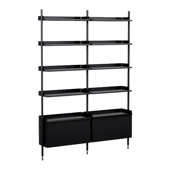
- Page 1 – INSTRUCTION MANUAL – PIER SYSTEM DESIGN BY RONAN & ERWAN BOUROULLEC...
- Page 4 – PARTS – Screw Connector Wall plug Allen key Mounting tool Screw Wall bracket Shelf Work shelf wall bracket Work shelf Coat rack Work shelf screw Wire shelf ...
- Page 5 Protect the products from scratches and other damage while assembling.
-
Page 6: Installation Of Connectors
– INSTALLATION OF CONNECTORS – When assembling your Pier System, you first need to identify where on the profiles the shelves are going to be mounted. This page features three standard configurations, with markings for where the connectors that hold the shelves are to be mounted. - Page 7 CONFIGURATION 2 CONFIGURATION 3...
- Page 8 – NOTICE – When assembling the Pier system, you need to be a minimum of two people.
-
Page 9: Securing To The Wall
– SECURING TO THE WALL – Pier System is secured to the wall with a wall bracket. The wall bracket must be connected to a shelf that is mounted above the 14th hole in the profile, counting from the bottom. - Page 10 – INSTALLATION OF WALL BRACKET – Make sure you have mounted all connectors 4. Identify your wall type. If it is a brick wall or on your profiles before going ahead. solid concrete, insert the provided wall plugs F. . Other wall types may require other types of fastening.
- Page 11 8. Insert the wall plug. 9. Move the wall bracket back up and insert the next screw. Do not tighten it completely yet. 10. Use a spirit level (or the mounting The provided wall plugs and screws are tool ) to make sure the wall bracket is designed for brick wall or solid concrete only.
- Page 12 CONFIGURATION 1 1. Start by laying a Cabinet and a Shelf down on their backs. Then Make sure you have finished the first fasten them to the pre-assembled steps with mounting connectors and connectors on the Profiles the first wall bracket before going sliding them into the cut-outs.
- Page 13 4. Slide the Mounting tool into the top Make sure the connectors on the back of the connector on the profile. shelf go into the designated cut-outs on the wall bracket. 5. Go back to pages 10-11 and follow the instructions to mount the next wall bracket.
- Page 15 7. Lay the other Cabinet on the floor and connect the last Profile by sliding the cabinet into the cut-outs of the connectors. 8. Lift the cabinet and profile and slide into the connectors of the middle profile. 9.
- Page 16 CONFIGURATION 2 1. Start by laying a Cabinet and a Shelf down on their backs. Then fasten them to the pre-assembled Make sure you have finished the first steps with mounting connectors and connectors on the Profiles the first wall bracket before going sliding them into the cut-outs.
- Page 17 Make sure the connectors on the back of the 4. Slide the Mounting tool into the shelf go into the designated cut-outs on the connector where the Work shelf will sit. wall bracket. 5. Go back to pages 10-11 and follow the 3.
- Page 18 6. Slide the Work shelf on. Since the 7. Secure the work shelf by inserting screws right profile is not yet fastened, you need on the underside of the shelf, and tighten them to be a minimum of two people to line with Allen key D.
- Page 19 go into the designated cut-outs on the wall 8. Slide the Mounting tool E. into the top bracket. connector of the middle profile. 11. Finally you can adjust the height of the feet 9. Go back to pages 10-11 and follow the of your shelving by first loosening the nut right instructions to mount the next wall bracket.
- Page 20 CONFIGURATION 3 1. Slide the Mounting tool into the top connector on the first profile. 2. Go back to pages 10-11 and follow the Make sure to have finished instructions to mount the wall bracket. the first step with mounting all connectors on the profiles 3.
- Page 21 4. Slide the Wire shelf and Coat rack into the connectors on the profiles. 5. Rescrew the connectors that were removed in STEP 3.
- Page 22 6. Slide a Shelf into the top connectors on the profiles. Make sure the connectors on the back of the shelf go into the designated cut-outs on the wall bracket. 7. Slide the Mounting tool into the top connector on the middle profile.
- Page 23 8. Go back to pages 10-11 and follow the instructions to mount the next wall bracket. 9. After mounting the wall bracket, remove the two connectors as illustrated.
- Page 24 10. Slide a Wire shelf into the connector on the profile. 11. Slide the wire shelf with the profile into the connectors on the middle profile. Then add the second wire shelf and the coat rack.
- Page 25 12. Rescrew the connectors that were Finally, you can adjust the height of the feet removed in STEP 9. of your shelving by first loosening the nut right under the profile. Use the provided 13. Slide the top shelf into the connectors ...
-
Page 26: Care And Maintenance
– CARE & MAINTENANCE – Our Care & Maintenance offers guidance for optimal maintenance of your HAY product. It includes advice and instructions on cleaning and caring for specific materials to prolong the life of your furniture. Please find our Care & Maintenance... - Page 32 Havnen 1 8700 Horsens Denmark +45 4282 0282 / hay@hay.com 08/04/2022...
Need help?
Do you have a question about the PIER SYSTEM and is the answer not in the manual?
Questions and answers