Table of Contents
Advertisement
Quick Links
Advertisement
Table of Contents

Related Manuals for Aaeon EMB-Q77B


Summary of Contents for Aaeon EMB-Q77B
- Page 1 EMB-Q77B...
- Page 2 E8890 First Edition January 2014 Copyright Notice This document is copyrighted, 2014. All rights are reserved. The original manufacturer reserves the right to make improvements to the products described in this manual at any time without notice. No part of this manual may be reproduced, copied, translated, or transmitted in any form or by any means without the prior written permission of the original manufacturer.
-
Page 3: Table Of Contents
3.2.2 System Date [Day xx/xx/xxxx] ......... 3-3 Advanced menu ................3-4 3.3.1 ICC Spread Spectrum ............. 3-4 3.3.2 AAEON ICC Spread Spectrum ........3-4 3.3.3 ACPI Settings ..............3-4 3.3.4 S5 RTC Wake Settings ........... 3-5 3.3.5 Trusted Computing ............3-5... - Page 4 3.3.6 CPU Configuration ............3-5 3.3.7 SATA Configuration ............3-6 3.3.8 Intel TXT(LT) Configuration ..........3-6 3.3.9 AMT Configuration ............3-7 3.3.10 USB Configuration ............3-7 3.3.11 NCT6779D Super IO Configuration ........ 3-8 3.3.12 NCT6779D H/W Monitor ..........3-8 3.3.13 CPU PPM Configuration ..........3-8 Chipset ..................3-9 3.4.1 Power Mode [ATX Type] ..........3-9 3.4.2 PCH-IO Configuration .............
-
Page 5: Chapter 1: Product Overview
Chapter 1 Product overview Package contents Check your industrial motherboard package for the following items. 1 x Industrial Motherboard 1 x SATA Cable 1 x I/O Shield 1 x Support CD If any of the above items is damaged or missing, contact your distributor or sales representative immediately. -
Page 6: Specifications
Up to 1920 x 1200 @60Hz Storage 2 X SATA 6Gb/s connectors (gray) 2 x SATA 3Gb/s connectors (blue) Supports RAID 0,1, 5, and 10 configurations 4 x USB 3.0/2.0 ports ( 4 ports at the back panel) 4 x USB 2.0/1.1 ports (4 ports at mid-board) EMB-Q77B... - Page 7 Display 1 x HDMI port 1 x VGA port Audio 3 Audio jack (Line-in, Mic-in, Line-out) 2 x LAN (RJ-45) ports Serial Port 1 x RS-232/422/485 supports 5V/12V/RI option (COM1, D-Sub 9) 1 x RS-232 (COM2, D-Sub 9) PS/2 Port 1 x PS/2 Keyboard port 1 x PS/2 Mouse port 1 x 4-pin CPU Fan connector...
- Page 8 1 x Front panel connector 1 x AT/ATX mode select jumper 1 x CMOS jumper OTHERS Operating System Windows XP 32bit ® Support Windows XP 64bit ® Windows 7 32bit ® Windows 7 64bit ® Windows ® Linux Fedrora NOTE: Specifications are subject to change without notice. EMB-Q77B...
-
Page 9: Chapter 2: Motherboard Information
Chapter 2 Motherboard information Before you proceed Take note of the following precautions before you install motherboard components or change any motherboard settings. CAUTION! • Unplug the power cord from the wall socket before touching any component. • Before handling components, use a grounded wrist strap or touch a safely grounded object or a metal object, such as the power supply case, to avoid damaging them due to static electricity. -
Page 10: Motherboard Layout
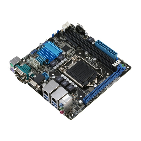
CAUTION! Do not overtighten the screws! Doing so can damage the motherboard. 17.0cm(6.7in) COM1 CLRTC CHASSIS _VSET USB56 USB1112 KBMS_USB910 Intel ® Super 1442 EATX12V Intel 82583V Place this side LAN2_USB3_34 towards the rear of the chassis LAN1_USB3_12 DIS_ME Intel AUDIO 82579LM SB_PWR PCIEX16 EMB-Q77B... - Page 11 Connectors/Jumpers/Slots Page Serial ATA 6.0Gb/s connectors (7-pin SATA6G_1, SATA6G_2) 2-21 CPU and chassis fan connectors (4-pin CPU_FAN, 4-pin CHA_FAN) 2-19 COM1 Ring/+5V/+12V selection (COM1_VSET) 2-14 USB 2.0 connector (10-1 pin USB56, USB1112) 2-22 Serial ATA 3.0Gb/s connectors (7-pin SATA3G_1, SATA3G_2) 2-21 Intel LGA1155 CPU socket...
-
Page 12: Screw Size
Screw size 2.3.1 Component side EMB-Q77B... -
Page 13: Solder Side
2.3.2 Solder side Chapter 2: Motherboard information... -
Page 14: Central Processing Unit (Cpu)
Intel® 3rd/2nd Generation Core™ i7 / Core™ i5 / Core™ i3 / Pentium / Celeron ® ® processors. EMB-Q77B CPU socket LGA1155 IMPORTANT: Unplug all power cables before installing the CPU. CAUTION! • Upon purchase of the motherboard, ensure that the PnP cap is on the socket and the socket contacts are not bent. -
Page 15: Installing The Cpu
2.4.1 Installing the CPU CAUTION! The LGA1156 CPU is incompatible with the LGA1155 socket. DO NOT install a LGA1156 CPU on the LGA1155 socket. Chapter 2: Motherboard information... - Page 16 EMB-Q77B...
-
Page 17: Cpu Heatsink And Fan Assembly Installation
2.4.2 CPU heatsink and fan assembly installation CAUTION! Apply the Thermal Interface Material to the CPU heatsink and CPU before you install the heatsink and fan if necessary. To install the CPU heatsink and fan assembly Chapter 2: Motherboard information... - Page 18 To uninstall the CPU heatsink and fan assembly EMB-Q77B 2-10...
-
Page 19: System Memory
DDR2 DIMM socket. DDR3 modules are developed for better performance with less power consumption. The figure below illustrates the location of the DDR3 DIMM sockets: Channel Sockets Channel A DIMM_A1 Channel B DIMM_B1 EMB-Q77B 240-pin DDR3 DIMM sockets Chapter 2: Motherboard information 2-11... -
Page 20: Installing A Dimm
2.5.1 Installing a DIMM To remove a DIMM EMB-Q77B 2-12... -
Page 21: Jumpers
CMOS RTC RAM data. The onboard button cell battery powers the RAM data in CMOS, which include system setup information such as system passwords. EMB-Q77B Clear RTC RAM To erase the RTC RAM: Turn OFF the computer and unplug the power cord. - Page 22 Management Engine (ME) boot from ® recovery mode when ME become corrupted. DIS_ME ME Enable ME Disable (Default) EMB-Q77B Intel ME jumper ® COM1 Ring/+5V/+12V selection (COM1_VSET) Com1_Vset PIN 1 EMB-Q77B COM VSET connector Setting Pins +12V Ring (Default) EMB-Q77B 2-14...
-
Page 23: Onboard Leds
The illustration below shows the location of the onboard LED. SB_PWR Standby Power Powered Off EMB-Q77B Onboard LED Chapter 2: Motherboard information 2-15... -
Page 24: Connectors
LED indications. LAN port LED indications Speed Activity Link ACT/LINK LED SPEED LED Status Description Status Description No link 10 Mbps connection ORANGE Linked ORANGE 100 Mbps connection LAN port BLINKING Data activity GREEN 1 Gbps connection EMB-Q77B 2-16... - Page 25 Line In port (light blue). This port connects the tape, CD, DVD player, or other audio sources. Line Out port (lime). This port connects to a headphone or a speaker. In a 4-channel, 6-channel and 8-channel configurations, the function of this port becomes Front Speaker Out. Microphone port (pink). This port connects a microphone. NOTE: Refer to the audio configuration table below for the function of the audio ports in the 2.1, 4.1, 5.1, or 7.1-channel configuration.
-
Page 26: Internal Connectors
+5 Volts PSON# +3 Volts -12 Volts +3 Volts +3 Volts PIN 1 EMB-Q77B ATX power connectors IMPORTANT: • For a fully configured system, we recommend that you use a power supply unit (PSU) that complies with ATX 12 V Specification 2.0 (or later version) and provides a minimum power of 230W. • DO NOT forget to connect the 4-pin ATX +12V power plug. Otherwise, the system will not have enough power. - Page 27 CPU_FAN SENSE EMB-Q77B CPU fan connector CAUTION: Do not forget to connect the fan cables to the fan connectors. Insufficient air flow inside the system may damage the motherboard components. These are not jumpers! Do not place jumper caps on the fan...
- Page 28 HDD_LED- PWR_LED+ HDD_LED+ PIN 1 EMB-Q77B System panel connector • System power LED (2-pin PWR_LED) This 2-pin connector is for the system power LED. Connect the chassis power LED cable to this connector. The system power LED lights up when you turn on the system power, and blinks when the system is in sleep mode.
- Page 29 Serial ATA 3.0Gb/s connectors (7-pin SATA3G_1, SATA3G_2) These connectors connect to Serial ATA 3.0 Gb/s hard disk drives and optical drives via Serial ATA 3.0 Gb/s signal cables. EMB-Q77B SATA 3.0Gb/s connectors NOTES: • You must install Windows XP Service Pack 3 or later version before using ®...
- Page 30 The USB module cable is purchased separately. Speaker connector (4-pin SPEAKER) The 4-pin connector is for the chassis-mounted system warning speaker. The speaker allows you to hear system beeps and warnings. SPEAKER PIN 1 Speaker Out EMB-Q77B Speaker Out Connector EMB-Q77B 2-22...
-
Page 31: Chapter 3: Bios Setup
Chapter 3 BIOS setup BIOS setup program Use the BIOS Setup program to update the BIOS or configure its parameters. The BIOS screens include navigation keys and brief online help to guide you in using the BIOS Setup program. Entering BIOS Setup at startup To enter BIOS Setup at startup: Press <Delete> during the Power-On Self Test (POST). If you do not press <Delete>, POST continues with its routine. -
Page 32: Bios Menu Screen
For selecting the exit options and loading default settings. Save & For selecting the exit options and loading default settings. Exit To select an item on the menu bar, press the right or left arrow key on the keyboard until the desired item is highlighted. EMB-Q77B... -
Page 33: Main Menu
Main menu When you enter the BIOS Setup program, the Main menu screen appears, giving you an overview of the basic system information. Refer to section 3.1.1 BIOS menu screen for information on the menu screen items and how to navigate through them. Aptio Setup Utility - Copyright (C) 2012 American Megatrends, Inc. -
Page 34: Advanced Menu
This item allows you to enable or disable the Spread Spectrum function for BCLK, DMI, PEG, PCIe, PCI33, SATA, USB3. Configuration options: [Enabled] [Disabled] 3.3.2 AAEON ICC Spread Spectrum This item provides the AAEON ICC Spread Spectrum default value. 3.3.3 ACPI Settings The items in this menu allows you to configure the system ACPI parameters. ACPI Sleep State [S3 only (Suspend to...] Allows you to select the ACPI sleep state that the system will enter when the SUSPEND button is pressed. Configuration options: [Suspend Disabled] [S1... -
Page 35: S5 Rtc Wake Settings
3.3.4 S5 RTC Wake Settings This item allows you to enable the system to wake up from S5 state using an alert event. Wake system with Fixed Time [Disabled] Allows you to enable or disable the system’s wake-on alert event. When enabled, the system wakes up on the specified time. -
Page 36: Sata Configuration
Enables Secure Mode Extensions. [Disabled] Disables Secure Mode Extensions. Intel TXT(LT) Support [Enabled] Enables support for Intel Trusted Execution Technology. [Disabled] Disables support for Intel Trusted Execution Technology. To enable Intel TXT(LT) Support, SMX and VT-d items should also be enabled. EMB-Q77B... -
Page 37: Amt Configuration
3.3.9 AMT Configuration The items in this menu allow you to change the Intel Active Management ® Technology (AMT) feature. Intel AMT [Enabled] ® Allow you to enable or disable the Intel Active Management Technology (AMT) in ® the BIOS extension. Configuration options: [Enabled] [Disabled] • iAMT H/W is always enabled. This option just controls the BIOS extension execution. If enabled, this requires additional firmware in the SPI device. -
Page 38: Nct6779D Super Io Configuration
NCT6779D H/W Monitor NCT6779D H/W Monitor H/W Monitor The items in this menu allows you to monitor the hardware status. 3.3.13 CPU PPM Configuration CPU PPM Configuration The items in this menu allows you to enable or disable the Intel SpeedStep. Configuration options: [Enabled] [Disabled] EMB-Q77B... -
Page 39: Chipset
Chipset The Chipset menu allows you to change the advanced chipset settings. Select an item then press <Enter> to display the sub-menu. 3.4.1 Power Mode [ATX Type] Allows you to select the power supply type. Configuration options: [ATX Type] [AT Type] 3.4.2 PCH-IO Configuration PCIE Express Configuration Allows you to configure the PCI Express settings. PCH Azalia Configuration Allows you to configure the PCH Azalia settings. -
Page 40: Boot Menu
The Boot menu items allow you to change the system boot options. 3.5.1 Boot Configuration Quiet Boot [Enabled] Enables or disables the Quiet Boot option. Configuration options: [Enabled] [Disabled] Launch PXE OpROM policy [Disabled] Controls the launch of UEFI and Legacy PXE OpROM. Configuration options: [Disabled] [Enabled] EMB-Q77B 3-10... -
Page 41: Security Menu
Security menu The Security menu items allow you to change the system security settings. Administrator Password If you have set an administrator password, we recommend that you enter the administrator password for accessing the system. Otherwise, you might be able to see or change only selected fields in the BIOS setup program. -
Page 42: Save & Exit Menu
Select Yes to load the default values. Save as User Defaults This option allows you to save the current changes as the user’s default values. Restore User Defaults This option allows you to load the user’s default values. EMB-Q77B 3-12... -
Page 43: Appendix
Check local regulations for disposal of electronic products. DO NOT throw the mercury-containing button cell battery in municipal waste. This symbol of the crossed out wheeled bin indicates that the battery should not be placed in municipal waste. EMB-Q77B Q77B... - Page 44 印 刷 電 路 板 及 其 × ○ ○ ○ ○ ○ 電子組件 外 部 信 號 連 接 頭 × ○ ○ ○ ○ ○ 及線材 ○: 表示該有毒有害物質在該部件所有均質材料中的含量均在 SJ/T 11363- 2006 標准規定的限量要求以下。 ×: 表示該有毒有害物質至少在該部件的某一均質材料中的含量超出 SJ/T 11363-2006 標准規定的限量要求,然該部件仍符合歐盟指令 2002/95/ E� 的規范。 備註:此產品所標示之環保使用期限,係指在一般正常使用狀況下。 EMB-Q77B...
Need help?
Do you have a question about the EMB-Q77B and is the answer not in the manual?
Questions and answers