Advertisement
Quick Links
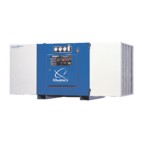
Quincy QMB/T
Electronic Control
This manual contains important safety information and should be made available
to all personnel who operate and/or maintain this product. Carefully read this
manual before attempting to operate or perform maintenance on this compressor.
Manual No. 65004-FA
Series
™
Instruction Manual
Quincy
Compressor
T r u e B l u e R e l i a b i l i t y
February 1998 Edition
®
TM
Advertisement

Related Manuals for Quincy QMB Series


Summary of Contents for Quincy QMB Series
- Page 1 Quincy QMB/T Series ™ Electronic Control Instruction Manual This manual contains important safety information and should be made available to all personnel who operate and/or maintain this product. Carefully read this manual before attempting to operate or perform maintenance on this compressor.
- Page 3 ® QMB/T Control Operations This manual describes the microprocessor control for the QMB/T series of Air Compressors. The decal at the right shows the control layout for the electronic control panel. The primary controls are on the right hand side of the panel, with the selected item being displayed on the LED digits in the top window.
-
Page 4: Basic Controls
BASIC CONTROLS: 1) MENU - This button scrolls through the set parameters as indicated by the LED lamps to the left, in the following order: a) System Pressure (default) b) Discharge Temperature c) Running (Total) Hours; Shows 'run' followed by the hours in alternating form. - Page 5 SYSTEM INDICATORS: RUN STATUS indicates that the compressor is in a run state. A steady light indicates that the compressor is running. If this light is flashing, and the compressor is in a stopped condition, the compressor will re-start at any time. This also indicates that the compressor is about to start, when the auto-restart option is enabled.
- Page 6 MENU 02: FILTER SERVICE HOURS LED 1: This is the separator service hours setup. The display will show the hours remaining, alternating with 'SEPA'. On servicing the separator, this counter is set to the desired service interval. LED 2: This is the air filter service hours setup. The display will show the hours remaining, alternating with'AIr.F'.
- Page 7 FAULTS: 1) EMERGENCY STOP: Pressing this button will cause the immediate halting of compressor operation. This is a redundant control. The microcontroller is signaled to halt operations and power is removed from all control relays; causing all circuits to open up. The LED indicators at the side of the panel will flash and 'STOP' will flash on the numeric display.
- Page 8 SERVICE REPLACEMENTS: Prior to attempting any repairs of the electronic control or related components, disconnect and lock out all power supplies to the compressor plus any remote controllers. Assure yourself that power is removed from the compressor by checking for any AC voltage at the line side of the motor starter. Replacing sensors or transducers: To replace a temperature sensor (HAT probe), disconnect conduit from elbow of probe.
- Page 9 WIRING DIAGRAM - ACROSS THE LINE STARTING...
- Page 10 WIRING DIAGRAM - WYE-DELTA STARTING...
- Page 12 T r u e B l u e R e l i a b i l i t y Rotary/Vacuum/Systems: 251.937.5900 Reciprocating/Systems: 217.222.7700 Nearest Distributor: 888.424.7729 © 2003 Quincy Compressor, an EnPro Industries company EnPro Industries company EnPro Industries E-mail: trueblue@quincycompressor.com All Rights Reserved. Litho in U.S.A. Discover:...
Need help?
Do you have a question about the QMB Series and is the answer not in the manual?
Questions and answers