Advertisement
Quick Links
THIS MACHINE MUST BE CONNECTED TO TWO DIFFERENT POWER
SUPPLIES: THREE-PHASE SUPPLY FOR THE COMPRESSOR SINGLE-
PHASE SUPPLY FOR THE DRYER
READ THIS MANUAL CAREFULLY BEFORE CARRYING OUT ANY OPERATIONS ON THE COMPRESSOR UNIT.
WARNING: ALWAYS WAIT FOR FIVE MINUTES BEFORE REMOVING THE FRONT COVER (INSTRUMENT PANEL).
USE A SPECIFIC INSTRUMENT TO CHECK THAT THERE ARE NO DANGEROUS VOLTAGES BEFORE PERFORMING
OPERATIONS ON THE MOTOR.
CONTENTS
PART A: INFORMATION FOR THE USER
1.0
GENERAL CHARACTERISTICS
2.0
INTENDED USE
3.0
OPERATION
4.0
GENERAL SAFETY STANDARDS
5.0
DESCRIPTION OF DANGER SIGNALS
6.0
DANGER ZONES
7.0
SAFETY DEVICES
8.0
POSITION OF PLATES
9.0
COMPRESSOR ROOM
10.0
TRANSPORT AND HANDLING
11.0
UNPACKING
12.0
INSTALLATION
13.0
DIMENSIONS AND TECHNICAL DATA
14.0
MACHINE ILLUSTRATION
15.0
ORDINARY MAINTENANCE TO BE DONE BY THE USER
16.0
PERIODS OF INACTIVITY
17.0
SCRAPPING THE UNIT
18.0
LIST OF SPARE PARTS FOR ROUTINE MAINTENANCE
19.0
TROUBLE-SHOOTING AND EMERGENCY REMEDIES
MANUAL USE AND MAINTENANCE
SILENCED SCREW ROTARY COMPRESSOR UNITS
QGS 20 - 25 - 30 - 40
PART B: INFORMATION RESERVED FOR TECHNICALLY SKILLED
20.0
21.0
22.0
23.0
24.0
25.0
26.0
27.0
IMPORTANT: A COPY OF THE WIRING DIAGRAMS CAN BE FOUND
INSIDE THE ELECTRIC PANEL OF THE COMPRESSOR.
PERSONNEL
STARTING UP
GENERAL ORDINARY MAINTENANCE REQUIRES
TRAINED PERSONNEL
CHANGING THE OIL
CHANGING THE OIL SEPARATING FILTER
BELT TENSION
REPLACING THE ELECTRIC MOTOR
OLEOPNEUMATIC DIAGRAM
CALIBRATIONS FOR DRYER
Cod. 9828093237 01 ed. 02/2023 - 1
ENGLISH
Codice
9828093237 01
Date 02/2023
Advertisement

Related Manuals for Quincy QGS 20


Summary of Contents for Quincy QGS 20
- Page 1 MANUAL USE AND MAINTENANCE Date 02/2023 SILENCED SCREW ROTARY COMPRESSOR UNITS QGS 20 - 25 - 30 - 40 THIS MACHINE MUST BE CONNECTED TO TWO DIFFERENT POWER SUPPLIES: THREE-PHASE SUPPLY FOR THE COMPRESSOR SINGLE- PHASE SUPPLY FOR THE DRYER READ THIS MANUAL CAREFULLY BEFORE CARRYING OUT ANY OPERATIONS ON THE COMPRESSOR UNIT.
- Page 2 ENGLISH MACHINE AND MANUFACTURER IDENTIFICATION DATA 1) Position of the identification plate ADDRESSES OF ASSISTANCE CENTRES In the event of breakdown or malfunction of the machine, switch it off and do not tamper with it. If repairs are needed, apply only to a technical assistance center approved by the manufacturer and insist on the use of original spare parts. Failure to comply with the above may endanger the safety of the machine.
- Page 3 ENGLISH AIR RECEIVER AND SAFETY VALVE: - To limit internal corrosion, which could compromise the safety of the compressed air tank, the condensation that is produced must be discharged at least once a day. If an automatic drain fitted to the air receiver is present, it is necessary to check that it is working correctly every week and repair it if necessary.
- Page 4 ENGLISH 4.0 GENERAL SAFETY STANDARDS The appliance may be used only by specially trained and authorized personnel. Any tampering with the machine or alterations not approved beforehand by the Manufacturer relieve the latter of responsibility for any damage resulting from the above actions. The removal of or tampering with the safety devices constitutes a violation of the European Standards on safety.
- Page 5 ENGLISH 6.0 DANGERS ZONES 6.1 DANGERS ZONES FOR COMPRESSOR UNIT Risks present on the whole machine FIG. 3 Cod. 9828093237 01 ed. 02/2023 - 5...
- Page 6 ENGLISH 6.2 DANGERS ZONES FOR DRYER UNIT AND TANK Risks present on the whole machine FIG. 3A 7.0 SAFETY DEVICES 7.1 SAFETY DEVICES FOR SCREW COMPRESSOR (Fig. 4) 1) Safety screws 4) Emergency stop button with mechanical seal and rotation release. 2) Front panels and door to the electric panel, opened with a special key 5) Oil filling cap (with safety breather) 3) Fixed protection device - cooling fan / pulleys...
- Page 7 ENGLISH 7.2 SAFETY DEVICES FOR DRYER UNIT AND TANK 1) Safety valve 3) Fan protection 2) Earth 4) Capacitor FIG. 5 8.0 POSITION OF PLATES 8.1 POSITION OF THE DANGER PLATES FOR COMPRESSOR UNIT The plates fitted on the compressor unit are part of the machine; they have been applied for safety purposes and must not be removed or spoiled for any reason.
- Page 8 ENGLISH 8.2 POSITION OF THE DANGER PLATES FOR DRYER UNIT AND TANK The plates fitted on the compressor unit are part of the machine; they have been applied for safety purposes and must not be removed or spoiled for any reason. 1) Dangers label Cod.
- Page 9 ENGLISH 8.3 POSITION OF THE DATA PLATE FOR COMPRESSOR UNIT 1) Identification plate 2) Direction of rotation 3) Drain condensate of the oil tank FIG. 8 Power supply label Compressor power supply Dryer power supply (Only for machine with dryer) Cod.
- Page 10 ENGLISH 8.4 POSITION OF THE DATA PLATE FOR DRYER – AIR RECEIVER FIG. 9 9.0 COMPRESSOR ROOM 9.1 FLOOR The floor must be even and of industrial type; the total weight of the machine is shown in the Chap. 13.0 Remember the total weight of the machine when positioning it.
- Page 11 ENGLISH 12.0 INSTALLATION 12.1 POSITIONING After unpacking the equipment and preparing the compressor room, put the machine into position, checking the following items: • Ensure that there is sufficient space around the machine to allow maintenance (see Fig. 12). FIG. 12 SPACE FOR MAINTENANCE MINIMUM mt 1,5 (in) 59 PROTECT THE POWER...
- Page 12 ENGLISH 12.3 CONNECTION TO THE COMPRESSED AIR NETWORK Fit a manual interception valve Ref. 1 between the machine and the compressed air network so that the compressor may be isolated during maintenance, operations (see figure 13). PIPES, FITTINGS AND CONNECTIONS USED FOR THE CONNECTION OF THE ELECTROCOMPRESSOR TO THE COMPRESSED AIR NETWORK MUST BE SUITABLE TO THE USE ACCORDING TO THE PRESCRIPTIONS OF THE REGULATIONS IN FORCE IN THE COUNTRY OF USE.
- Page 13 ENGLISH Without Dryer Dimensions mm (in) Air connection HP 20-25-30-40 1130 1250 kW 15-18,5-22-30 1” (44,5) (30,7) (49,2) Net weight (Lb.) HP 20 HP 25 HP 30 HP 40 kW 15 kW 18,5 kW 22 kW30 Weight (without / with) dryer 1087 With air receiver 500 l.
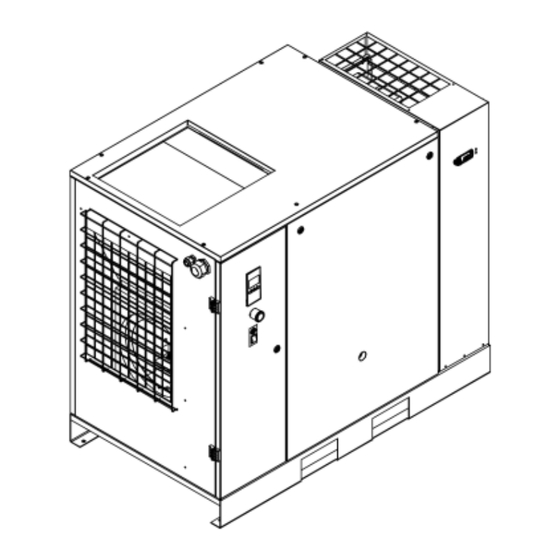
- Page 14 ENGLISH 14.0 MACHINE ILLUSTRATION 14.1 GENERAL LAYOUT FOR DRYER AND TANK 1 Air suction filter 12 Oil discharge 2 Thermostatic valve 13 Oil tank 3 Oil filter 14 Pressure gauge tank 4 Air-oil cooler 15 Control card 5 Filter panel 16 Safety valve () 6 Belt tightening system 17 Condensate manual drainage...
- Page 15 ENGLISH 14.2 COMMAND AND CONTROLLERS BEFORE CARRYING OUT THE OPERATION TEST, READ CAREFULLY AND ACQUIRE A GOOD KNOWLEDGE OF THE COMMAND FUNCTIONS. FIG. 16 1) Controller 2) Emergency stop button with mechanical seal and rotation release 14.3 COMPRESSOR CONTROLLER FIG. 17 14.3.1 INTRODUCTION In general, the controller has following functions: - Controlling the unit...
- Page 16 ENGLISH PROTECTING THE COMPRESSOR SHUTDOWN If the outlet element temperature exceeds the programmed shutdown level, the unit will be stopped. This will be indicated on the display of the controller. The unit will also be stopped in case of overload of the drive motor. Air-cooled units will also be stopped in the event of overload of the fan motor Before remedying, consult the safety precautions.
- Page 17 ENGLISH ARAVF label The ARAVF label is attached on the side panel, next to the controller, with the goal of warning users of the risks linked to the function. INTEGRATED CONNECTIVITY Integrated connectivity allows you to monitor and control the unit by using just your smartphone. Use the application to check the real-time performance indicator like pressure, temperature, running hours and operation mode.
- Page 18 ENGLISH Operation sign Is lit when the unit is running in automatic operation. Voltage sign Indicates that the voltage is switched on. Up button Use these buttons to scroll through the menu. This button starts the unit. The operation sign (4) lights up. Start/stop button The controller is operative.
- Page 19 ENGLISH 14.3.3 ICONS USED ON THE DISPLAY STATUS ICONS ICON DESCRIPTION Motor stopped Running unloaded Running loaded Remote Machine Control Mode, active Automatic Restart After Voltage Failure, active Emergency stop Main motor Element outlet temperature Units of pressure, outlet Units of temperature, outlet Dryer Units of dryer LAT temperature (Low ambient temperature) Multiply value x1000...
- Page 20 ENGLISH ICON DESCRIPTION Fixed: LAN cable connected Blinking: LAN cable not connected Bluetooth connection Wi-Fi signal 100% Wi-Fi signal 75% Wi-Fi signal 50% Wi-Fi signal 25% Cloud connected Fixed: Over-the-air (OTA) update available Blinking: Over-the-air (OTA) update in progress NOTE: This chapter gives a general survey of available icons.
- Page 21 ENGLISH 14.3.5 WARNING DESCRIPTION A Warning will appear in the event of: Too high temperature at the outlet of the compressor’s element (TT90) Too low temperature at the outlet of the compressor’s element (TT90) If unit is connected to cloud you will receive real time warning notification. COMPRESSOR ELEMENT OUTLET TEMPERATURE (TT90) If the outlet temperature of the compressor's element exceeds the warning level warning (factory setting 110°C / 230°F) LED (2) will light up: Main screen with temperature outlet warning...
- Page 22 ENGLISH 14.3.6 SHUTDOWN DESCRIPTION The unit will be shutdown in case of: Outlet temperature exceeds the shutdown level, detected by temperature sensor (TT90) or temperature switches (TSHH11- TSHH21) Error of the outlet pressure (PT20) /temperature sensor (TT90) Outlet pressure too high Overload of the main motor/fan motor If unit is connected to the cloud you will receive real time shutdown notification.
- Page 23 ENGLISH COMPRESSOR ELEMENT OUTLET TEMPERATURE BY TEMPERATURE SWITCH (TSHH11 / TSHH21) If the outlet temperature of the compressor element triggers for temperature switch the compressor will be shutdown, alarm LED (2) will flash, automatic operation LED (4) will go out and the following screen will appear: Main screen with temperature switch shutdown The related pictograph will appear flashing.
- Page 24 ENGLISH COMPRESSOR OUTLET PRESSURE TOO HIGH If the outlet pressure of the compressor exceeds the shutdown level (factory setting 1.5bar / 22psi over the maximum pressure of compressor) the compressor will be shutdown, alarm LED (2) will flash, automatic operation LED (4) will go out and the following screen will appear: High outlet pressure The unit of pressure bar/psi/MPa will appear flashing.
- Page 25 ENGLISH 14.3.7 SERVICE WARNING A service warning will appear when the service timer has reached the programmed time interval. If the service timer exceeds the programmed time interval, alarm LED (3) will light up. Stop the unit, switch off the voltage and carry out the required service actions. See section Preventive Maintenance.
- Page 26 ENGLISH 14.3.9 SCROLLING THROUGH SCREENS Scroll buttons (6-8) can be used to scroll through all screens. For most screens, the unit of measurement and the related pictograph are shown together with the screen number. Example: The screen shows the screen number P.SEt, the unit used bar and the related symbol for pressure unit. Press Enter key (9) to call up the actual running hours.
- Page 27 ENGLISH Press Enter button (9) to modify. Starting/loading pressure changing The pictograph shows starting/loading pressure and the value starts blinking. Press Scroll button (6-8) to modify the starting/loading pressure and press enter button (9) to confirm. The unloading pressure on secondary row will update in consequence to have optimal pressure range. Stopping/unloading pressure changing The pictograph shows stopping/unloading pressure and the value starts blinking.
- Page 28 ENGLISH 14.3.11 CALLING UP RUNNING HOURS Starting from the Main screen: Press Scroll button (6-8) until HoUr is shown on the display. Running hours screen Press Enter button (9). Running hours value The screen shows the unit used (x1000 hrs) and the value (11.25): the running hours of the unit are 11250 hours. 28 - Cod.
- Page 29 ENGLISH 14.3.12 CALLING UP SOFTWARE RELEASE Starting from the Main screen: Press Scroll button (6-8) until SoFt is shown on the display. Software release screen Press Enter button (9) to show the software release version. 14.3.13 CALLING UP BLUETOOTH PAIRING/ DISCOVERY MODE For Bluetooth connectivity a paring with the device is necessary, see section Connectivity.
- Page 30 ENGLISH 14.3.14 ADVANCED MENU To enter inside the advanced menu Press buttons (6) and (8) together. Advanced menu consists by following functions: CONTROLLER SCREENS DESIGNATION FUNCTION SEru Service mode See section Calling-up Service mode tESt Screen Test See section Calling-up Screen Test FACt Factory reset See section Calling-up Factory reset...
- Page 31 ENGLISH 14.3.16 SCREEN TEST Starting from the Main screen: Press buttons (6) and (8) together to enter inside advanced menu. Press Scroll button (6-8) until tESt is shown on the display. Use enter button (9) to confirm the screen test. The display now shows all icons that can be displayed: Test screen 14.3.17 CALLING UP FACTORY RESET...
- Page 32 ENGLISH In order to have an overview of all the features available in the App we refer to the APP guidelines document which can be found in the media section of the App. Unit configuration and control are made possible by Bluetooth communication with digital signature. To connect the unit to the cloud for monitoring purposes, a Wi-Fi connection or alternatively an Ethernet network with access to Internet is required.
- Page 33 ENGLISH Follow the instructions in the application. At the start of the update the following icon on the controller screen starts blinking Do not turn the power off the unit during the firmware update or interrupt this procedure. During the update the machine will be stopped;...
- Page 34 ENGLISH DRYER CONTROLLER (In case of compressor version with integrated dryer) 14.4 BEFORE CARRYING OUT THE OPERATION TEST, READ CAREFULLY AND ACQUIRE A GOOD KNOWLEDGE OF THE COMMAND FUNCTIONS. FIG. 17/B Reference Name Alarm icon Refrigerant compressor icon Fan icon Dryer ON PDP indicator Button to snooze or to reset the alarm...
- Page 35 ENGLISH REMOTE ALARM FUNCTION The controller allows to remotely control a number of alarms. This is managed by means of a free NC (Normally Closed) contact. The contact opens in case of an alarm or when the dryer is switched off. (Contact customer center for more details) TROUBLE-SHOOTING AND EMERGENCY REMEDIES N.B.
- Page 36 ENGLISH “EE” ALARM EE alarm is shown when internal EPROM errors happens, if this warning will appear, the dryer will stop running. The error can be reset by pressing one of the four buttons of the controller, anyway please replace the controller itself. NOTE: In case of EE alarm please contact your tech support.
- Page 37 ENGLISH HOW TO RESET THE MAINTENANCE WARNING: FOLLOW STEPS 1 TO 12 DOWN Push and hold buttons “SET” and PDP is flashing between standard Message “SE” appears on display. view and “SE” alarm “DOWN” to enter in the menu. Message “rS” appears on display. Push and release button “SET”.
- Page 38 ENGLISH PROCEDURE TO SET THE SERVICE INTERVAL ON PDP DEVICE DOWN PDP is showing standard view. Push and hold buttons “SET” and Message “SE” appears on display. “DOWN” to enter in the menu. Current service interval is displayed. Select desired service interval Push and release “SET”...
- Page 39 ENGLISH 15.0 ORDINARY MAINTENANCE TO BE DONE BY THE USER BEFORE CARRYING OUT ANY MAINTENANCE, IT IS OBLIGATORY TO STOP THE MACHINE AND DISCONNECT IT FROM THE POWER MAINS AND FROM THE COMPRESSED AIR DISTRIBUTION NETWORK. The user may carry out the maintenance jobs described in this chapter. The more complex maintenance jobs, which require professionally skilled personnel, are listed in the chapter on GENERAL ROUTINE MAINTENANCE.
- Page 40 ENGLISH 15.3 DRAINING CONDENSATE FROM THE OIL TANK If the compressor work cycle includes long pauses during which the machine cools down, a certain amount of condensate will gather in the oil tank. This happens, for example, when stopping overnight or at weekends. The condensate must be drained off every 50 hours or every week.
- Page 41 ENGLISH OIL LEVEL CHECK Running unit: - Foam level is in the center of sight glass. Machine just stopped: - When foam disappears, the sight glass must be almost completely filled with oil. ATTENZIONE: - Do not check level if machine is standing for more than 10 minutes. - Do not overfill.
- Page 42 ENGLISH BEFORE PERFORMING ANY MAINTENANCE, IT IS MANDATORY TO STOP THE MACHINE AND DISCONNECT IT FROM THE POWER MAINS AND FROM THE COMPRESSED AIR DISTRIBUTION NETWORK. 15.5 CLEANING THE FILTRATION PANEL - Switch off the machine with pushbutton Ref. 1 Fig. 18: In this way, the machine stops after 30 seconds of idle running. - Disconnect the power supply by means of the disconnector switch, Ref.
- Page 43 ENGLISH - Close the fixed protection (machine cover) Ref. 2 Fig. 19 device again, using the appropriate safety screws. 15.7 CHECKING THE AUTOMATIC AND MANUAL CONDENSATION EMPTYING AND THE DRAIN STATUS LED(FOR DRYER AND TANK) BEFORE CARRYING OUT ANY MAINTENANCE, IT IS OBLIGATORY TO STOP THE MACHINE AND DISCONNECT IT FROM THE POWER MAINS AND FROM THE COMPRESSED AIR DISTRIBUTION NETWORK.
- Page 44 ENGLISH - Install the filter, fix the plug. - Re-assemble the panel Ref.3 Fig. 20 - Close the drain valve Ref.2 Fig. 20 15.9 CLEANING THE CONDENSER UNIT (ON THE DRYER IF FITTED) BEFORE CARRYING OUT ANY MAINTENANCE, IT IS OBLIGATORY TO STOP THE MACHINE AND DISCONNECT IT FROM THE POWER MAINS AND FROM THE COMPRESSED AIR DISTRIBUTION NETWORK.
- Page 45 ENGLISH 16.0 PERIOD OF INACTIVITY If the machine has to remain inactive for a long period: - Switch off the machine with pushbutton Ref. 4 Fig. 22: In this way, the machine stops after 30 seconds of idle running. - Close the cock Ref. 1 Fig. 22. (machine with/without tank) and push the emergency stop button on cubicle door. - Remove the panel Ref.
- Page 46 ◼ ◼ Separator cartridge air/oil 6221372550 ◼ ◼ ◼ Filtering element 2202260065 ◼ Filtering element 2204121301 ◼ ◼ ◼ ◼ () Please contact your Quincy compressor dealer for oil replacement. () FIG. 23 46 - Cod. 9828093237 01 ed. 02/2023...
- Page 47 ENGLISH 19.0 TROUBLE-SHOOTING AND EMERGENCY REMEDIES N.B. OPERATIONS MARKED ◼ ◼ MUST BE CARRIED OUT BY PROFESSIONALLY SKILLED PERSONNEL APPROVED THE MANUFACTURER PROFESSIONALLY SKILLED PERSONNEL MUST CARRY OUT ALL WORK. BEFORE CARRYNG OUT ANY MAINTENANCE JOBS, IT IS OBLIGATORY TO STOP THE MACHINE AND DISCONNECT IT FROM THE POWER MAINS. 19.1 TROUBLE-SHOOTING AND EMERGENCY REMEDIES FOR SCREW COMPRESSOR FAULT FOUND POSSIBLE CAUSES...
- Page 48 ENGLISH 19.2 TROUBLE-SHOOTING AND EMERGENCY REMEDIES FOR DRYER PROFESSIONALLY SKILLED PERSONNEL MUST CARRY OUT ALL WORK. BEFORE CARRYNG OUT ANY MAINTENANCE JOBS, IT IS OBLIGATORY TO STOP THE MACHINE AND DISCONNECT IT FROM THE POWER MAINS. N.B. OPERATIONS MARKED ◼ ◼ MUST BE CARRIED OUT BY PROFESSIONALLY SKILLED PERSONNEL APPROVED THE MANUFACTURER FAULT FOUND POSSIBLE CAUSES...
- Page 49 ENGLISH PART “B” THIS PART “B” OF THE INSTRUCTIONS MANUAL IS RESERVED FOR PROFESSIONALLY SKILLED PERSONNEL APPROVED THE MANUFACTURER 20.0 STARTING UP BEFORE CARRYING OUT ANY OPERATION ON THE MACHINE, ENSURE THAT THE ELECTRIC POWER SUPPLY HAS BEEN DISCONNECTED. 20.1 PREPARING FOR SETTING UP After checking everything as indicated in Chap.
- Page 50 ENGLISH 20.3 CHECK THE DIRECTION OF ROTATION - Check that all fixed guards are in their correct position. - Apply voltage to the control panel by operating on the disconnector switch Ref. 1 Fig. 25. - If the rotation is not correct, the compressor will not start, and the related alarm will be shown in the controller display. PROFESSIONALLY SKILLED PERSONNEL MUST CARRY OUT ALL WORK ON THE ELECTRIC PLANT, HOWEVER SLIGHT.
- Page 51 ENGLISH 21.0 GENERAL ORDINARY MAINTENANCE REQUIRES TRAINED PERSONNEL BEFORE CARRYING OUT ANY MAINTENANCE JOBS, IT IS OBLIGATORY TO STOP THE MACHINE AND DISCONNECT IT FROM THE POWER MAINS. IT’S ALSO NECESSARY TO DEPRESSURIZE THE MACHINE. MAINTENANCE SCHEDULE These maintenance intervals are recommended for work environments that are not dusty and are well ventilated. For particularly dusty environments, double the frequency of controls.
- Page 52 ENGLISH 22.0 CHANGING THE OIL BEFORE CARRYING OUT ANY MAINTENANCE JOBS, IT IS OBLIGATORY TO STOP THE MACHINE AND DISCONNECT IT FROM THE POWER MAINS AND FROM THE COMPRESSED AIR DISTRIBUTION NETWORK. Oil changing is an important operation for the compressor: If the lubrication of the bearings is not efficient, the compressor life will be short.
- Page 53 ENGLISH 23.0 CHANGING THE OIL SEPARATING FILTER BEFORE CARRYING OUT ANY MAINTENANCE THE MACHINE MUST BE STOPPED, CUT OFF THE MACHINE FROM THE ELECTRICAL MAINS AND FROM THE COMPRESSED AIR DISTRIBUTION CIRCUIT, CHECK THAT THE MACHINE IS NOT UNDER PRESSURE. Before proceeding with the replacement of the de-oiler filter or the oil filter check that there is no pressure in the machine: check the pressure gauge Ref.
- Page 54 ENGLISH 24.0 BELT TENSION BEFORE CARRYING OUT ANY MAINTENANCE THE MACHINE MUST BE STOPPED, CUT OFF THE MACHINE FROM THE ELECTRICAL MAINS AND FROM THE COMPRESSED AIR DISTRIBUTION CIRCUIT, CHECK THAT THE MACHINE IS NOT UNDER PRESSURE. Tightening or retightening new belts 1 - F= 11,2 Lb., force to be applied at the Proceed as follows: center line, at right angles to the new belt.
- Page 55 ENGLISH 25.0 REPLACING THE ELECTRIC MOTOR BEFORE CARRYING OUT ANY MAINTENANCE THE MACHINE MUST BE STOPPED, CUT OFF THE MACHINE FROM THE ELECTRICAL MAINS AND FROM THE COMPRESSED AIR DISTRIBUTION CIRCUIT, CHECK THAT THE MACHINE IS NOT UNDER PRESSURE. 25.1 DISASSEMBLING THE COOLING FAN AND CONVEYOR (Fig. 29) Proceed as follows: - Remove the external panels.
- Page 56 ENGLISH 26.0 OLEOPNEUMATIC DIAGRAM 1 AIR FILTER 13 AIR VESSEL 2 REGULATING VALVE 14 SAFETY VALVE 3 COMPRESSOR 15 SAFETY TERMOSTATIC 4 OIL DRAIN 16 ELECTRIC MOTOR 5 AIR-OIL RECEIVER 17 NO-LOAD RUNNING SOLENOID VALVE 6 OIL FILTER 18 MANOMETER 7 THERMOSTATIC VALVE 19 MANUAL DRAIN VALVE 8 OIL COOLER...
- Page 57 ENGLISH 27.0 CALIBRATION FOR DRYER BYPASS VALVE FOR HOT GAS N.B. These valves have already been calibrated and they do not require any adjustment. A dew point different from the rated one generally depends on causes which are not attributable to their operation. 1) Closing cap 2) Adjusting screw WORKING PRESSURES AND TEMPERATURES OF R134a / R410a...
- Page 58 ENGLISH 58 - Cod. 9828093237 01 ed. 02/2023...
Need help?
Do you have a question about the QGS 20 and is the answer not in the manual?
Questions and answers