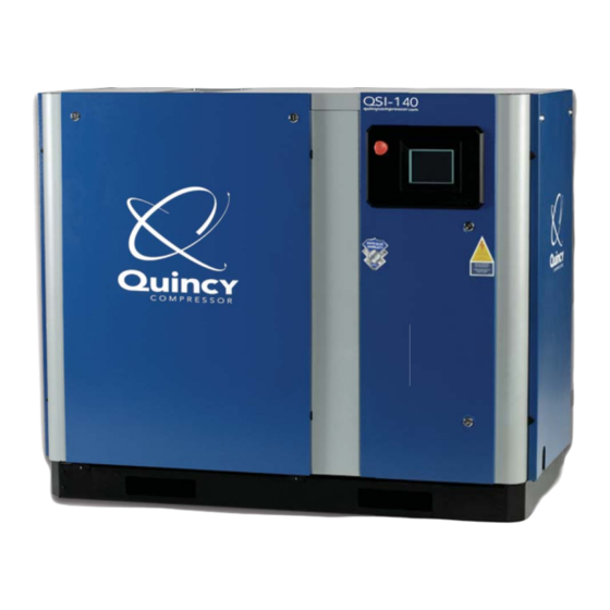
Quincy QSI-90 Instruction Manual

Quincy QSI-90 Instruction Manual

Direct drive air compressors
Table of Contents

Advertisement

A-Z COPM
Địa chỉ: 365 QL 51, P. Long Bình Tân, Biên Hòa, Đồng Nai
Điện Thoại: 0888.624.124
Email: maynenkhi.az@gmail.com
Website:maynenkhia-z.com
QSI-90/120/140
& QGV-20/25/30
This manual contains important safety information and should be made available to
all personnel who operate and/or maintain this product. Carefully read this manual
before attempting to operate or perform maintenance on this equipment.
Direct Drive Air Compressors
Instruction Manual
Manual No.
December 2012 Edition
2012200011

Advertisement

Table of Contents
loading

Summary of Contents for Quincy QSI-90

  • Page 1 Địa chỉ: 365 QL 51, P. Long Bình Tân, Biên Hòa, Đồng Nai Điện Thoại: 0888.624.124 Email: maynenkhi.az@gmail.com Website:maynenkhia-z.com QSI-90/120/140 & QGV-20/25/30 Direct Drive Air Compressors Instruction Manual This manual contains important safety information and should be made available to all personnel who operate and/or maintain this product.
  • Page 3: Table Of Contents

    Table of Contents Section I - General Information Safety Alert Symbols ......................1 Safety P recautions .......................2 Spare Parts Ordering Information ..................3 Serial/Model Identification Plate ..................3 Section II - Description General Description ......................4 The Compression Cycle ......................4 Air Flow ..........................5 Cooling System ........................5 Air-cooled Fluid Coolers ......................5 Aftercoolers .........................5 Moisture Separ ator ......................5...
  • Page 4 Converting to QuinSyn Plus ....................55 Sampling P rocedures ......................55 Understanding the Analysis Report ...................56 Fluid Parameters .......................58 Section VII - Troubleshooting Troubleshooting ........................60 Appendix A - Dimensional Drawings QSI-90/120/140 ......................66-73 QGV-20/25/30 ......................74-77 Appendix B - Technical Data QSI-90/120/140 ......................
  • Page 5: Section I - General Information

    Section I - General Information • Safety Alert Symbols • Safety Precautions • Spare Parts Ordering Information • Serial/Model Identification Plate Safety Alert Symbols IMPORTANT! Throughout this manual we have identified key hazards. The following symbols identify the level of hazard seriousness: DANGER! WARNING! This symbol identifies immediate...
  • Page 6: Safety Precautions

    Section I - General Information Safety Precautions ♦ A properly sized pressure relief valve Read this manual and follow all instructions must be installed in the discharge prior to installing or operating the piping ahead (upstream) of any shutoff compressor. valve (block valve), heat exchanger, Listed below are some, but not all, safety orifice or any potential blockage...
  • Page 7: Spare Parts Ordering Information

    Section I - General Information Spare Parts Ordering Information ♦ Use the correct fluid at all times. Quincy Compressor maintains replacement parts for Quincy compressors and ♦ Do not rely on the discharge air line accessories. A repair parts list is shipped check valve.
  • Page 8: Section Ii - Description

    fl ute pass the discharge port. Acoustical cabinets are standard on QSI The compressed air is then discharged into compressors. QSI-90, 120 and 140 units the air/fl uid reservoir. There are four or are available mounted on a 120 gallon fi...
  • Page 9: Air Flow

    Section II - Description Air Flow then discharged into the air/fl uid reservoir. When the compressor is operating, Compressed air passes through the air/ a partial vacuum is produced at the fl uid separator, then through a minimum compressor inlet. Air entering via the air pressure check valve, through the fi...
  • Page 10: Capacity Control System

    Section II - Description Capacity Control System When maximum pressure (typically 15 As the motor starts driving the compressor PSIG above normal full load pressure) rotors, air is drawn in, compressed and has been obtained in the air system, discharged into the system downstream. complete compressor unloading occurs.
  • Page 11: Standard Control Lights, Indicators & Gauges

    Section II - Description Standard Control Lights, Indicators & Gauges Hourmeter Indicates actual hours of operation on the compressor. Air Pressure Gauge This gauge indicates air pressure available for distribution to the service line. CAUTION! Main Power on Light Gauge may not register when the unit Indicates when power from the main is unloaded or off.
  • Page 12: Operating Modes

    Section II - Description Operating Modes Load/No Load In the Load/No Load mode, the compressor does not modulate the inlet valve. The valve is either fully open or it is WARNING! closed. If system demands include regular periods of air usage at less than full load, Never assume it is safe to work on a a large compressed air storage capability compressor because it is not operating.
  • Page 13: Electrical System

    Electrical system diagrams are shown in DANGER! the parts manual sent with the compressor. The appropriate diagram is also included in the control panel on all Quincy QSI High voltage could cause death or compressors. serious injury. Disconnect all power...
  • Page 14: Section Iii - Installation

    Section III - Installation • Receiving • Moving the Unit to the Installation Site • Location • Shipping Supports • Piping Connections • Pressure Vessels • Relief Valves • Electrical • Pneumatic Circuit Breakers or Velocity Fuses • Guards • Manual Vent and Shutoff Valves •...
  • Page 15: Location

    fl uid may need to be changed to exposed to a toxic, volatile or corrosive QuinSyn-PG in high humidity areas. atmosphere, nor should toxic, volatile Quincy QSI compressors are essentially or corrosive agents be stored near the vibration free, however, some customers compressor.
  • Page 16: Shipping Supports

    Section III - Installation Shipping Supports NOTICE! Shipping supports are used to secure the motor and airend during shipping to Once the compressor has been located prevent damage to the motor, airend, and secured at the installation site, the reservoir and the connections to these shipping supports must be removed components.
  • Page 17: Relief Valves

    ASME B19 safety standards. Failure to provide properly sized relief valves could result in death or serious injury. Electrical Quincy would like to emphasize the Before installation, the electrical supply importance of providing adequate should be checked for adequate wire size grounding for air compressors.
  • Page 18: Pneumatic Circuit Breakers Or Velocity Fuses

    Section III - Installation Pneumatic Circuit Breakers or Velocity Fuses Pneumatic safety devices are designed to The Occupational Safety and Health Act, prevent hoses from whipping, which could Section 1926.303 Paragraph 7 published result in a serious or fatal accident. in Code of Federal Regulations 29 CFR 1920.1 (revised 07/01/1982), states “all hoses exceeding 1/2”...
  • Page 19: Compressor Rotation

    Section III - Installation Compressor Rotation and warranty coverage will be voided. To Compressor rotation must be checked check for proper rotation, jog the starter prior to start-up. Proper rotation is button, allowing the motor to turn 2 or 3 clockwise (as viewed from the power- revolutions.
  • Page 20: Section Iv - Operating Procedures

    Section IV - Operating Procedures • Prior to Starting • Starting the Compressor • Stopping the Compressor • HMI Control Panel Operation Prior to Starting ♦ Check the fan and fan mounting for tightness. CAUTION! ♦ Manually rotate the compressor Provisions should be made to have the through enough revolutions to be instruction manual readily available...
  • Page 21: Starting The Compressor

    Section IV - Operating Procedures Starting the Compressor ♦ Secure all enclosure panels on ♦ Control settings have been adjusted at compressor. the factory; however, they should be checked during start-up and readjusted, ♦ Open the service valve to the plant air if necessary.
  • Page 22: Qsi Standard Controls

    Section IV - Operating Procedures QSI Standard Controls Main Display Screen: This is the main display screen, that shows the basic parameters and current conditions. Pressure, Temperature, operating status are all available at a glance. The main control buttons are present for Starting and Stopping the compressor.
  • Page 23 Section IV - Operating Procedures Three languages are built-in: English, Spanish and French. (Spanish shown) TEMP FAULT: The temperature probe is faulty, either an open circuit or shorted. PRES FAULT: The Pressure Transducer is faulty, either an open circuit or shorted. HIGH Temp: The Discharge Temperature was greater than the shutdown temperature.
  • Page 24 Section IV - Operating Procedures TIMES Menu: This menu displays the current operating hours and the Service time remaining on the various fi lter elements. When the fi lter hours reach ‘0’, an warning message will be displayed on the main display, indicating that the element should be checked.
  • Page 25 Section IV - Operating Procedures TREND DISPLAY(s): These 3 screens, display the last 16 hours of samples (one sample per 16 seconds). The buttons advance Left or Right, or Expand or Compress the plot. The time scale gives the number of measurements.
  • Page 26 Section IV - Operating Procedures EVENT LOG: The EVENT LOG, displays the faults or other alarms that are monitored, with the most recent being at the top of the list. The date and time are given for each event. Scroll buttons at the side (appear when list is greater than the window) allow viewing events not present in the display window.
  • Page 27 Section IV - Operating Procedures CONFIG: S.S. RAMP time is for Solid State / Soft Starts to match the ‘up to speed’ intervals. The Y/D delay sets the transition time for reduced voltage starts. The Capacity display requires the addition of a vacuum sensor and analog module to add a capacity gauge on the main running screen.
  • Page 28 Section IV - Operating Procedures CALIBRATE: This menu allows calibration of the temperature and pressure sensors. Quincy’s normal span is 0-300 for both the pressure transducer and the temperature sensor. For pressure, vent the sensor to atmosphere, and then press the ZERO button.
  • Page 29 Section IV - Operating Procedures RUN MODES: The settings in the BLUE box apply to the Continuous and AD modes only. Auto-restart activates the power-on starting of the compressor. This is to automatically restart after a power interruption. If the time is ‘0’, then this function is not active.
  • Page 30 Section IV - Operating Procedures LANGUAGE: Three languages are selectable from this menu. The current language is displayed at the top, and pressing the labeled button, selects the new language. FILTERS: This allows the setup of service interval for the various fi lters in the compressor. These times are counted down to 0, and a notice will be displayed on the main menu, to check the fi...
  • Page 31 Section IV - Operating Procedures UNITS: This sets the displayed units for the panel. NOTE: The PLC operates in Imperial units internally, so there may be some rounding when entering Metric values.
  • Page 32 Section IV - Operating Procedures Appendix A Adding Capacity Sensor to STD QSIi Return +24V 2091Z01PV2M11P1 Setra, or Eqv. These 2 switches Programming the PLC Remove the power from the compressor, and pull this cap off.
  • Page 33 Section IV - Operating Procedures Place the program cartridge into the socket and restore power. The PLC run status lights will be yellow for a second or two, then turn green. That signifi es that the program has been copied. Power down and remove the program cartridge, and replace the cover blank.
  • Page 34 Section IV - Operating Procedures The CP 243-1 IT Module, provides the connectivity to an Ethernet system, to provide the eMail notifi cation option on QSIi series compressors. The module contains the fi rmware that establishes the connection and protocol for communication, but needs to be setup according to the local conditions.
  • Page 35 Section IV - Operating Procedures Diagnostic LED’s: SF (red) is on if there is some system error. LINK will be green when an Ethernet connection is present. RX/TX will fl ash green when data is being passed, or attempting to pass. RUN will be green when the module is ready.
  • Page 36 Section IV - Operating Procedures Once communications is established, type ‘FTP’ and the network address. The module will respond with “Connected to …” with other information. It will then ask for a user input. This is ‘admin’ (lower case) and then will ask for a password, which is ‘quincy123’, also in lower case.
  • Page 37 Section IV - Operating Procedures TIMESTAMP=4539104E FILETYPE=EDB FILEFORMAT=01 FROM=Compressor@room.com SMTPSA1=172.26.66.87 SMTPSP1=25 SMTPSA2=0.0.0.0 SMTPSP2=25 00|TO|armor@quincycompressor.com 00|CC| 00|SU|Service 00|TX|A,%VD5000:8.0h%%VD5004:8.0h%%VD5008:8.0h%%VD5012:8.0h%%VD5016:8.0h %%VD5020:8.0h%%VD5024:8.0h%%VD5028:8.0h%%VD5032:8.0h%%VD5036:8.0h%%VD504 0:8.0h%%VD5044:8.0h%%VD5048:8.0h%%VD5052:8.0h%%VD5056:8.0h%%VD5060:8.0h% %VD5064:8.0h%%VD5068:8.0h%%VD5072:8.0h%%VD5076:8.0h%%VD5080:8.0h% 01|TO| 01|CC| 01|SU| 01|TX| ………….. Then, using a text editor like ‘Notepad’ or ‘Wordpad’, the fi le has the mail server location set for the plant’s mail server.
  • Page 38: Section V - Servicing

    Section V - Servicing • Preparing for Maintenance or Service • Safety • Maintenance Schedule • Water Removal • Air/Fluid Separator Element Safety • Air Filter • Changing the Compressor Fluid • Shaft Seal NOTICE! • Differential Pilot Valve Maintenance should be performed by •...
  • Page 39: Maintenance Schedule

    Section V - Servicing Maintenance Schedule This Schedule is intended to be used as a guideline only. Depending on the specifi c operating conditions of your QSI compressor, maintenance requirements may vary. The instructions in this section will give more details about determining when specifi c service should be performed.
  • Page 40: Maintenance & Troubleshooting

    Section V - Servicing Maintenance & Troubleshooting Use a “Megger” periodically WARNING! to ensure that the integrity of the winding insulation hes been UL Listed motors must only be serviced maintained. Record the Megger by UL Approved Authorized Baldor readings. Immediately investigate Service Centers if these motors are any significant drop in insulation to be returned to a hazardous and/or...
  • Page 41: Water Removal

    Section V - Servicing Water Removal 5 minutes. Then open the drain valve. Water is heavier than the compressor Water vapor may condense in the reservoir fl uid and will collect at the bottom of the and must be removed. The frequency reservoir.
  • Page 42: Shaft Seal

    Disassemble the seal adapter as are required for a successful seal follows: replacement. Ask your Quincy distributor a. With the face of the seal for complete illustrated instructions adapter up, insert two small, fl at...
  • Page 43 Section V - Servicing Preparation for New Seal Installation Seal Installation ♦ ♦ Apply a thin coat of compressor fluid to Inspect the compressor shaft for burrs the outer face of the wear sleeve and or deep scratches at the wear sleeve seal lip.
  • Page 44: Differential Pilot Valve

    Section V - Servicing Differential Pilot Valve WARNING! on the inlet valve, causing the valve to modulate toward its closed position, thereby reducing the volume of air being Never adjust the pressure higher than compressed. the factory setting. Death or serious injury and compressor or property To raise the pressure, turn the adjusting damage could result.
  • Page 45: Electronic Control

    Section V - Servicing Electronic Control To replace the electronic control, remove Prior to attempting any repairs of the the screws attaching control to the panel. electronic control or related components, Remove and discard wire tie-wraps. disconnect and lock out all power supplies to the compressor plus any remote controllers.
  • Page 46 Section V - Servicing ASSEMBLING THE FACE SEAL END 3) POSITION TO FITTING 1) CHECK SEALING SURFACES ENSURE THAT O-RING IS PROPERLY SEATED IN THE GROOVE. POSITION AND HOLD FLAT SEALING CHECK SEALING SURFACE FACE AGAINST O-RING. AND GROOVE FOR DAMAGE OR MATERIAL BUILDUP.
  • Page 47: Water Coolers

    Section V - Servicing Water Coolers When zinc anodes are used for a particular application, they should be inspected two weeks after initial startup and also anodes need to be checked once a month until a wear pattern is established for a given application/environment. The zinc anodes must be replaced when the zinc body is 75% depleted.
  • Page 48: Section Vi - Compressor Fluids

    • Understanding the Analysis Report • Fluid Parameters A fl uid tag is attached to each Quincy The three functions of compressor fl uid rotary screw compressor indicating the are: type of fl uid provided in the initial fi ll. All ♦...
  • Page 49: Lubrication

    fi ltration or carryover. Consult the Quincy the fl uid throughout the machine. Service Department before changing Each Quincy compressor is fi lled at the brands of fl uid. factory with the correct amount of one of the synthetic fl uid listed in the Fluid Specifi...
  • Page 50: Fluid Filter

    • burnt fuel - Air intake should provide contaminant- i.e. exhaust from: forklifts, boilers, free, cool air. A Quincy heavy-duty intake jet aircraft fi lter will reduce the risk of abrasion and • ni trogen o xides increased wear.
  • Page 51: Fluid Analysis Program - General

    Section VI - Compressor Fluids Fluid Analysis Program - General Analysis until a history of performance Quincy’s fl uid analysis program is offered in a specifi c compressor application is to all customers using QuinSyn fl uids established. Once the appropriate drain in Quincy Compressor ®...
  • Page 52: Quinsyn Plus

    Section VI - Compressor Fluids QuinSyn Plus Applications QuinSyn Plus is the factory fi ll for Quincy rotary screw compressors. QuinSyn Plus is suited for use in rotary screw air compressors operating in QuinSyn Plus is an ISO 46 viscosity fl uid...
  • Page 53: Quinsyn Pg

    485°F compliance, fluid samples of QuinSyn Fire Point ASTM D92 525°F ® PG must be sent to Quincy Compressor Fluid Analysis a minimum of every 2,000 hours or every 6 month for light Applications use units. QuinSyn PG is the recommended fl uid in high humidity applications due to its ability to hold water.
  • Page 54: Quinsyn Xp

    fl uid sampling done in accordance with Local, State, and program). Federal regulations. Should condensate need to be treated, Quincy’s QIOWA fl uid/ water separators are required. Typical Properties of QuinSyn XP ISO 68 Viscosity @ 100°F ASTM D445 60.0 cSt.
  • Page 55: Quinsyn F

    Section VI - Compressor Fluids QuinSyn F Typical Properties of QuinSyn F QuinSyn F is Quincy’s food grade fl uid, suitable in applications where there may Viscosity @ 100°F ASTM D445 43.0 cSt. be incidental food contact. Compliant with Viscosity @ 210°F ASTM D445 7.5 cSt.
  • Page 56: Cleaning And Flushing With Quinsyn Flush

    Analysis at 200 hours. cleaning, fi ll with a fresh charge of the QuinSyn fl uid selected for your machine. Varnished Machines Send fl uid sample to Quincy Compressor ® Fluid Analysis at 200 hours. Always clean slightly varnished machines using mineral oils or PAO fl...
  • Page 57: Converting To Quinsyn Pg

    Run compressor for 300 hours. Take a fl uid foam may be visible in the fluid level ® sample and send to Quincy Compressor sightglass. If this occurs, repeat the Fluid Analysis to determine if further flushing procedure.
  • Page 58: Converting To Quinsyn Xp

    Drain and refi ll with Flush and run machine until it reaches a fresh charge of new QuinSyn normal operating temperature. Drain XP. Send a fl uid sample to Quincy and refi ll with a fresh charge of new Compressor ®...
  • Page 59: Sampling Procedures

    Quincy Compressor Fluid Analysis 2300 James Savage Road Sample From Reservoir Filter Midland, MI 48642-6535 Sample Bottle Label Shipping Label Note: A fl uid sample valve kit is available from Quincy Compressor. Contact the Service Department and ask for part number 143286.
  • Page 60: Understanding The Analysis Report

    (Ba) (Ca) (Mg) (Mo) (Na) (Si) (Zn) Quincy Compressor Fluid Analysis 2300 James Savage Road Midland, MI 48642-6535 Thank you for this opportunity to provide technical assistance to your company. If you have any questions about this report please contact us at 1-800-637-8628 or fax 1-517-496-2313.
  • Page 61 fl uid and fi lter. This statement will also note any problems g) SERIAL NUMBER - The unit serial that need attention. number of the Quincy compressor the fl uid sample was taken from. m) PHYSICAL PROPERTIES RESULTS - Particle size is measured in microns.
  • Page 62: Fluid Parameters

    Section VI - Compressor Fluids FLUID PARAMETERS QuinSyn PG, QuinSyn XP & QuinSyn Plus ROPERTY NITS ETHOD LUID LUID ARGINAL NACCEPTABLE ASTM D-445 45-55 41,61 <41, >61 (1) ISCOSITY 40°C 58-75 50, 85 <50, >85 (1) 42-51 38, 56 <38, >56 (1) KOH/ ASTM D-947 <0.2...
  • Page 63 Section VI - Compressor Fluids FLUID PARAMETERS QuinSyn F ROPERTY NITS ETHOD LUID ARGINAL NACCEPTABLE 40°C ASTM D-445 41-51 39, 56 <39, >56 (1) ISCOSITY . TAN KOH/ ASTM D-947 0.8-0.9 >1 (1) ADDITIVE METALS 5-20 >20 ARIUM LASMA MISSION 5-20 >20 ALCIUM...
  • Page 64: Troubleshooting

    Section VII - Troubleshooting Failure to Start: “ON” “ON” OWER NOT TURNED URN THE POWER BY CLOSING THE MAIN DISCONNECT SWITCH OR CIRCUIT BREAKER LOWN CONTROL CIRCUIT FUSE EPLACE FUSE IND AND CORRECT CAUSE AFETY CIRCUIT SHUTDOWN RESULTING FROM HIGH DISCHARGE AIR ORRECT THE SITUATION IN ACCORDANCE WITH THE “H ”...
  • Page 65 Section VII - Troubleshooting Thermal Overload Relays Tripping: XCESSIVE DISCHARGE PRESSURE OWER FULL LOAD PRESSURE SETTING AT CONTROL PANEL OW VOLTAGE HECK VOLTAGE AND AMPERAGES WHILE OPERATING AT FULL LOAD PRESSURE OOSE OVERLOAD CONNECTION IGHTEN MOUNTING SCREWS ON THERMAL OVERLOAD NCORRECT THERMAL OVERLOAD RELAY SETTING HECK MOTOR NAMEPLATE AND COMPARE TO OVERLOAD RELAY SETTING...
  • Page 66 Section VII - Troubleshooting High Discharge Air Temperature and/or High Fluid Injection Temperature: NADEQUATE CIRCULATION OF COOLING AIR AT THE COOLER HECK LOCATION OF COOLER AND ASSURE NO RESTRICTION TO FREE CIRCULATION OF COOLING AIR HECK COOLER FIN AND CLEAN AS NECESSARY OW FLUID LEVEL IN RESERVOIR DD FLUID TO RECOMMENDED LEVEL HECK FLUID SYSTEM...
  • Page 67 Section VII - Troubleshooting Fluid Discharge Out Blowdown Valve: OO HIGH FLUID LEVEL IN RESERVOIR DJUST FLUID LEVEL TO RECOMMENDED FLUID LEVEL BY DRAINING THE RESERVOIR SE FLUID LEVEL GAUGE AS A GUIDE FLUID RESERVOIR BLOWS DOWN TOO FAST HECK FOR PROPER BLOWDOWN VALVE SIZE “I NLET VALVE NOT CLOSING COMPLETELY ORRECT IN ACCORDANCE WITH INSTRUCTIONS IN...
  • Page 68 Section VII - Troubleshooting Inlet Valve Not Opening Or Closing In Relation To Air Demand: MPROPER PRESSURE SETTING OR FAULTY SENSOR DJUST AIR PRESSURE SETTING OR REPLACE SENSOR IF FAULTY XCESSIVE MOISTURE IN CONTROL AIR LINE AT AIR CYLINDER ERVICE CONTROL AIR LINE FILTER DAILY MPROPER FUNCTIONING OF INLET VALVE PISTON HECK PISTON AND CYLINDER BORE EPAIR OR REPLACE AS...
  • Page 69 Section VII - Troubleshooting Compressor Will Not Time-out Or Shut Down When Unloaded (Auto/Dual Only): EAKS IN CONTROL LINES HECK AND REPAIR ANY LEAKS EAKS IN SERVICE LINES HECK PLANT AIR DISTRIBUTION SYSTEM FOR LEAKS AULTY AIR PRESSURE SENSORS EPLACE AS NECESSARY Excessive Water in Plant Air Distribution System: LOGGED MOISTURE SEPARATOR...
  • Page 70: Appendix A - Dimensional Drawings

    Appendix A - Dimensional Drawings QSI-90/120/140 (micro)
  • Page 71: Qsi-90/120/140

    Appendix A - Dimensional Drawings QSI-90/120/140 (micro,dry)
  • Page 72 Appendix A - Dimensional Drawings QSI-90/120/140 (micro,tank mounted)
  • Page 73 Appendix A - Dimensional Drawings QSI-90/120/140 (micro,dry,tank mounted)
  • Page 74 Appendix A - Dimensional Drawings QSI-90/120/140 (guage)
  • Page 75 Appendix A - Dimensional Drawings QSI-90/120/140 (guage,dry)
  • Page 76 Appendix A - Dimensional Drawings QSI-90/120/140 (guage,tank mounted)
  • Page 77 Appendix A - Dimensional Drawings QSI-90/120/140 (guage,dry,tank mounted)
  • Page 78: Qgv-20/25/30

    Appendix A - Dimensional Drawings QGV-20/25/30 (460V)
  • Page 79 Appendix A - Dimensional Drawings QGV-20/25/30 (460V,dry)
  • Page 80 Appendix A - Dimensional Drawings QGV-20/25/30 (460V,tank mounted)
  • Page 81 Appendix A - Dimensional Drawings QGV-20/25/30 (460V,dry,tank mounted)
  • Page 82 Appendix B - Technical Data QSI-90 Operating Pressure Capacity acfm Nameplate HP Max Operating Pressure Min Operating Pressure Max Ambient Temperature °F Min Ambient Temperature °F Rotor Diameter 120.5 120.5 120.5 120.5 Nominal Driven Rotor Speed 3600 3600 3600 3600 Service Line Connection 1”...
  • Page 83 Appendix B - Technical Data QSI-120 Operating Pressure Capacity acfm Nameplate HP Max Operating Pressure Min Operating Pressure Max Ambient Temperature °F Min Ambient Temperature °F Rotor Diameter 120.5 120.5 120.5 120.5 Nominal Driven Rotor Speed 3600 3600 3600 3600 Service Line Connection 1”...
  • Page 84 Appendix B - Technical Data QSI-140 Operating Pressure Capacity acfm Nameplate HP Max Operating Pressure Min Operating Pressure Max Ambient Temperature °F Min Ambient Temperature °F Rotor Diameter 120.5 120.5 120.5 Nominal Driven Rotor Speed 3600 3600 3600 Service Line Connection 1”...
  • Page 85 Appendix B - Technical Data QGV-20 Operating Pressure Full Load Pressure - Maximum - Minimum Max Operating Pressure Min Operating Pressure Max Ambient Temperature °F Min Ambient Temperature °F Rotor Diameter 120.5 Sound Level Free Air Delivery Compressor RPM - 1000 15.2 13.6 11.5...
  • Page 86 Appendix B - Technical Data QGV-25 Operating Pressure Full Load Pressure - Maximum - Minimum Max Operating Pressure Min Operating Pressure Max Ambient Temperature °F Min Ambient Temperature °F Rotor Diameter 120.5 Sound Level Free Air Delivery Compressor RPM - 1000 26.1 19.9 22.0...
  • Page 87 Appendix B - Technical Data QGV-30 Operating Pressure Full Load Pressure - Maximum - Minimum Max Operating Pressure Min Operating Pressure Max Ambient Temperature °F Min Ambient Temperature °F Rotor Diameter 120.5 Sound Level Free Air Delivery Compressor RPM - 1000 33.0 31.0 29.6...
  • Page 88 TANDARD ERMS AND ONDITIONS UINCY OMPRESSOR AND RTMAN LUID OWER IVISIONS LEGAL EFFECT: Except as expressly otherwise agreed to in writing by an authorized representative of Seller, the following terms and conditions shall apply to and form a part of this order and any additional and/or different terms of Buyer’s purchase order or other form of acceptance are rejected in advance and shall not become a part of this order.
  • Page 89 ENVIROMENTAL AND OSHA REQUIREMENTS: At the time of shipment of the equipment from the factory, Quincy Compressor / Ortman Fluid Power will comply with the various Federal, State and local laws and regulations concerning occupational health and safety and pollution. However, in the installation and...
  • Page 90 Notes ____________________________________________________________________ ____________________________________________________________________ ____________________________________________________________________ ____________________________________________________________________ ____________________________________________________________________ ____________________________________________________________________ ____________________________________________________________________ ____________________________________________________________________ ____________________________________________________________________ ____________________________________________________________________ ____________________________________________________________________ ____________________________________________________________________ ____________________________________________________________________ ____________________________________________________________________ ____________________________________________________________________ ____________________________________________________________________ ____________________________________________________________________ ____________________________________________________________________ ____________________________________________________________________ ____________________________________________________________________ ____________________________________________________________________ ____________________________________________________________________ ____________________________________________________________________ ____________________________________________________________________ ____________________________________________________________________ ____________________________________________________________________ ____________________________________________________________________ ____________________________________________________________________ ____________________________________________________________________ ____________________________________________________________________ ____________________________________________________________________ ____________________________________________________________________ ____________________________________________________________________ ____________________________________________________________________ ____________________________________________________________________...
  • Page 92 Quincy Compressor Products: 217.222.7700 © 2012 Quincy Compressor E-mail: info@quincycompressor.com All Rights Reserved. Litho in U.S.A. Website: www.quincycompressor.com...

This manual is also suitable for:

Qsi-140Qsi-120Qgv-30Qgv-20Qgv-25

Table of Contents