Advertisement
Quick Links
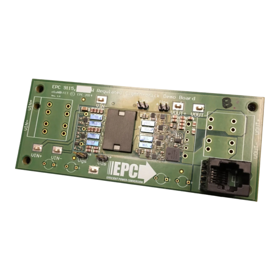
Demonstration Board
EPC9115
Quick Start Guide
1/8th Brick Converter
Featuring EPC2020 and EPC2021
For More Information:
Please contact info@epc-co.com
or your local sales representative
Visit our website:
www.epc-co.com
Sign-up to receive
EPC updates at
bit.ly/EPCupdates
or text "EPC" to 22828
EPC Products are distributed
through Digi-Key.
www.digikey.com
DESCRIPTION
The EPC9115 demonstration board is a fully regulated 300 kHz isolated DC/DC bus converter
with a 12 V, 42 A output and a input range of 48 – 60 V. The demonstration board features the
enhancement mode (eGaN®) field effect transistors (FETs), the EPC2020 (60 V) and EPC2021 (80 V),
along with eGaN FET specific integrated circuit drivers – the LM5113 half-bridge driver and
UCC27611 low side driver from Texas Instruments. The power stage is a conventional
hard-switched 300 kHz isolated buck converter. The EPC9115 board is intended to
showcase the superior performance that can be achieved using eGaN FETs and eGaN driver
together in a conventional topology.
The complete converter fits within a standard eighth-brick envelope, but the demonstration board
is oversized to allow connections for bench evaluation. There are also various probe points to
facilitate simple waveform measurement and efficiency calculation.
A complete block diagram of the circuit is given in Figure 1. The converter uses a full-bridge (FB)
primary power stage, a 4:1 transformer, and a center-tapped (CT) output stage with active reset
snubbers. Control is provided by a Microchip dsPIC® controller, and basic voltage mode control
is implemented. For more information on the EPC2020 and EPC2021 eGaN FETs, as well as the
gate drivers and controller, please refer to the datasheets available from EPC at www.epc-co.com,
www.ti.com, and www.microchip.com. These datasheets, should be read in conjunction with
this quick start guide.
Table 1: Performance Summary (V
SYMBOL
PARAMETER
V
Bus Input Voltage Range
IN
V
Output Voltage
OUT
I
Output Current
2
OUT
f
Switching Frequency
SW
Output Ripple Frequency
Peak Efficiency
Full Load Efficiency
Full Load Efficiency
Full Load Efficiency
Output voltage duty cycle limited to 98%
1
Maximum current limited by thermal considerations
2
Board placed vertical on long edge to aid convection – Do NOT operate horizontally without forced air cooling
3
Demonstration Board Notification
EPC9115 boards are intended for product evaluation purposes only and are not intended for commercial use. As evaluation tools, they are not designed for compliance with the European Union directive on
electromagnetic compatibility or any other such directives or regulations. As board builds are at times subject to product availability, it is possible that boards may contain components or assembly materials
that are not RoHS compliant. Efficient Power Conversion Corporation (EPC) makes no guarantee that the purchased board is 100% RoHS compliant. No Licenses are implied or granted under any patent
right or other intellectual property whatsoever. EPC assumes no liability for applications assistance, customer product design, software performance, or infringement of patents or any other intellectual
property rights of any kind.
EPC reserves the right at any time, without notice, to change said circuitry and specifications.
EPC – EFFICIENT POWER CONVERSION CORPORATION |
=52 V, T
= 25°C, 400 LFM unless otherwise specified)
IN
A
CONDITIONS
T
= 25°C, no forced air cooling
3
a
T
= 25°C, ~200 LFM
a
T
= 25°C, ~400 LFM
a
48 V
, 30 A I
IN
OUT
52 V
, 42 A I
IN
OUT
56 V
, 42 A I
IN
OUT
60 V
, 42 A I
IN
OUT
WWW.EPC-CO.COM
MIN
TYP
MAX
UNITS
48
52
60
V
11.4
12
12.1
V
1
5
A
35
A
42
A
300
kHz
600
kHz
96.7
%
96.4
%
96.3
%
96.1
%
| COPYRIGHT 2015
Advertisement

Related Manuals for EPC 9115


Summary of Contents for EPC 9115
- Page 1 As board builds are at times subject to product availability, it is possible that boards may contain components or assembly materials that are not RoHS compliant. Efficient Power Conversion Corporation (EPC) makes no guarantee that the purchased board is 100% RoHS compliant. No Licenses are implied or granted under any patent right or other intellectual property whatsoever.
-
Page 2: Quick Start Procedure
12*4.7 uF EPC2021 EPC2021 V_OUT- EPC2020 EPC2020 EPC2020 EPC2020 470nF V_BIAS_PRI Controller V_BIAS_SEC V_OUT_SNS snb1 I_OUT_SNS snb2 Figure 1: Block Diagram of EPC9115 Demonstration Board EPC – EFFICIENT POWER CONVERSION CORPORATION | WWW.EPC-CO.COM | COPYRIGHT 2015 | | PAGE 2... - Page 3 Gate Data are taken after converter reaches thermal steady state. 4 V/div Figure 4: Typical waveforms taken at 52 V to 12 V /42 A EPC – EFFICIENT POWER CONVERSION CORPORATION | WWW.EPC-CO.COM | COPYRIGHT 2015 | | PAGE 3...
-
Page 4: Operating Considerations
1V or less. 400 LFM Figure 6: Thermal images of EPC9115. Operating conditions: 400 LFM (2 m/s) forced convection, ambient temperature 27 °C, thermal steady state. EPC – EFFICIENT POWER CONVERSION CORPORATION | WWW.EPC-CO.COM | COPYRIGHT 2015 |... - Page 5 R21, R23, R28, R30, R37, R44, Resistor 49.9 Yageo RC0402FR-0749R9L R59, R60 R22, R25, R29, R32 Resistor ZERO Vishay CRCW04020000Z0ED R3, R4 Resistor 33.2 K Vishay RC0402FR-0733K2L EPC – EFFICIENT POWER CONVERSION CORPORATION | WWW.EPC-CO.COM | COPYRIGHT 2015 | | PAGE 5...
- Page 6 NVE Corporation IL611-1E magnetic isolator U8, U9 half-bridge eGaN gate driver LM5113 LM5113TME/NOPB CORE1 Planer E core Ferroxcube EQ20/R-3F35 CORE2 Planer I core Ferroxcube PLT20/S-3F35 EPC – EFFICIENT POWER CONVERSION CORPORATION | WWW.EPC-CO.COM | COPYRIGHT 2015 | | PAGE 6...
- Page 7 4.7 uF 35V OUT_ R ET OUT_ RET OUTER_METAL OUT_RET .1” Male Vert. .1” Male Vert. 3300P Figure 7: EPC9115 Demonstration board schematic - Power EPC – EFFICIENT POWER CONVERSION CORPORATION | WWW.EPC-CO.COM | COPYRIGHT 2015 | | PAGE 7...
- Page 8 LM5113 ZERO GPLR +5V0_SEC OUT_RET 0.22U VREF 4.99 GS2_2 49.9 DSP_SIG_SEC2 UCC27611DRV OUT_RET 4.99 GS2_1 Figure 8: EPC9115 Demonstration board schematic – Gate Drive OUT_RET EPC – EFFICIENT POWER CONVERSION CORPORATION | WWW.EPC-CO.COM | COPYRIGHT 2015 | | PAGE 8...
- Page 9 OUT_RET PGED LP2985 5V0 2.2U 2.2U PGEC IN CIRCUIT PROGRAM HEADER FOR CONTROLLING PARAMETERS, 12C Figure 9: EPC9115 Demonstration board schematic – Bias and Control EPC – EFFICIENT POWER CONVERSION CORPORATION | WWW.EPC-CO.COM | COPYRIGHT 2015 | | PAGE 9...
Need help?
Do you have a question about the 9115 and is the answer not in the manual?
Questions and answers