
Related Manuals for Kramer VA-16XL


Summary of Contents for Kramer VA-16XL
-
Page 1: User Manual
Kramer Electronics, Ltd. USER MANUAL Models: VA-8xl, 8 Channel Balanced Stereo Audio Amplifier VA-16xl, 16 Channel Balanced Stereo Audio Amplifier... -
Page 2: Table Of Contents
Figure 4: Unbalanced Audio Input Channel Figure 5: Unbalanced Audio Output Channel Figure 6: Connecting a VA-8xl or VA-16xl to a PC without using a Null-modem Adapter Figure 7: Rear Panel Dipswitches (Factory Default) Figure 8: Configuring up to 15 VA-8xl or VA-16xl Units... - Page 3 Table 2: Rear Panel VA-8xl / VA-16xl Features Table 3: Dipswitch Definitions Table 4: Machine # Dipswitch Settings Table 5: Technical Specifications of the VA-8xl or VA-16xl Table 6: Instruction Codes Table 7: Examples Table 8: VA-16xl Hex Codes for Gain Control (Attenuation)
-
Page 4: Introduction
GROUP 6: Accessories and Rack Adapters; GROUP 7: Scan Converters and Scalers; and GROUP 8: Cables and Connectors 2 Download up-to-date Kramer user manuals from the Internet at this URL: http://www.kramerelectronics.com/manuals.html 3 The complete list of Kramer cables is on our Web site at http://www.kramerelectronics.com (click “Cables and Connectors” in the Products section) -
Page 5: Overview
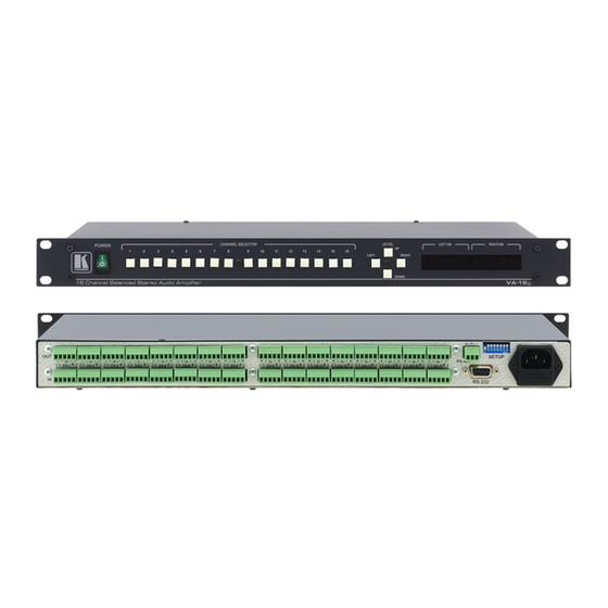
Figure 1 illustrates the VA-8xl 8 Channel Balanced Stereo Audio Amplifier and Figure 2 illustrates the VA-16xl 16 Channel Balanced Stereo Audio Amplifier. Table 1 defines the front panel of the VA-8xl and VA-16xl, and Table 2 defines the rear panel of the VA-8xl and VA-16xl. -
Page 6: Figure 1: Va-8Xl 8 Channel Balanced Stereo Audio Amplifier
Your VA-8xl and VA-16xl Figure 1: VA-8xl 8 Channel Balanced Stereo Audio Amplifier Figure 2: VA-16xl 16 Channel Balanced Stereo Audio Amplifier... -
Page 7: Operating Your Va-8Xl And Va-16Xl
Table 1: Front Panel VA-8xl / VA-16xl Features Feature POWER Switch CHANNEL SELECTOR Buttons DOWN Button LEFT Button UP Button RIGHT Button LEFT/dB 7-segment LED Display RIGHT/dB 7-segment LED Display Shows the gain of the selected right channel Table 2: Rear Panel VA-8xl / VA-16xl Features... -
Page 8: Figure 4: Unbalanced Audio Input Channel
VA-8xl or VA-16xl briefly scan each channel 7-segment LED Displays 1, and show its gain/attenuation level in dB. During regular work, the VA-8xl or VA-16xl show the status of the last channel you observed and/or changed. To observe the status of a Channel, do the following: •... -
Page 9: Controlling The Gain/Attenuation Of The Channels
Display and the setup number appears in the RIGHT /dB 7-segment LED Display. 1 When the LEDs are dimmed, you cannot change the gain or attenuation - the values are for observation only 2 Stored in the non-volatile memory Operating Your VA-8xl and VA-16xl 7-segment LED Displays KRAMER: SIMPLE CREATIVE TECHNOLOGY... -
Page 10: Serial Control Of The Va-8Xl Or Va-16Xl
Serial Control of the VA-8xl or VA-16xl You can control a single VA-8xl or VA-16xl unit (see section 6.1) or configure up to a 240 channel balanced stereo audio amplifier, using 15 VA-16xl units via RS-485 or RS-232 (see section 6.2). -
Page 11: Controlling A Single Va-8Xl Or Va-16Xl Unit
1 Switch OFF the power on each device before connecting it to your VA-8xl or VA-16xl. After connecting your VA-8xl or VA-16xl, switch on its power and then switch on the power on each device. Switching on the VA-8xl or VA-16xl, recalls the previous setup of all the channels from the non-volatile memory. -
Page 12: Dipswitch Settings
Serial Control of the VA-8xl or VA-16xl 6.1.2 Dipswitch Settings Configure the VA-8xl or VA-16xl by setting the dipswitches as Figure 7 and Table 3 define: Figure 7: Rear Panel Dipswitches (Factory Default) DIP # Function: Set the MACHINE # (see Table 4 in section 6.1.3) -
Page 13: Configuring Up To A 240 Channel Balanced Stereo Audio Amplifier
RS-485 ports on each of the VA-8xl or VA-16xl units (see section 6.2.1.2) 1 Switch OFF the power on each device before connecting it to a VA-8xl or VA-16xl unit. After connecting all the VA-8xl or VA-16xl units, switch on their power and then switch on the power on each device that connects to them. Switching on each VA-8xl or VA-16xl unit, recalls the previous setup of each channel from the non-volatile memory. -
Page 14: Figure 9: Preparing The Rs-232 Connectors
1 Choose the RS-232 control interface, for a range of about 25 meters used for a point-to-point connection 2 By preparing a special RS-232 cable (not required when connecting a stand-alone VA-8xl or VA-16xl unit (see section 6.1.1)), as illustrated in Figure 8 and Figure 9... -
Page 15: Figure 10: An Rs-485 Control Interface Setup
RS-485 port on the VP-43xl to the RS-485 ports on the VA-8xl or VA-16xl units) Figure 10: An RS-485 Control Interface Setup 1 Choose the RS-485 control interface, to operate the VA-8xl or VA-16xl from an extended distance of up to 1200 meters KRAMER: SIMPLE CREATIVE TECHNOLOGY... -
Page 16: Flash Memory Upgrade
Before installing the latest Kramer firmware version on a VA-8xl or VA-16xl unit, do the following: 1. Connect the RS-232 DB9 rear panel port on the VA-8xl or VA-16xl unit to the Null-modem adapter and connect the Null-modem adapter with a 9 wire flat cable to the RS-232 DB9 COM port on your PC (see section 6.1.1). -
Page 17: Figure 11: Splash Screen
Figure 12: Atmel – Flip Window 3. Press the keyboard shortcut key F4 (or select the “Read Configuration File” command from the File menu, or press the keys: Alt FR). The “Open Configuration File” window appears: KRAMER: SIMPLE CREATIVE TECHNOLOGY... -
Page 18: Figure 13: Open Configuration File Select Window
Flash Memory Upgrade Figure 13: Open Configuration File Select Window 4. Choose the file: “Va16xl.cfg” (by double-clicking it). If COM 2 was not selected (see section 7.2), an RS-232 error message appears. In the “Atmel – Flip” window, the Operations Flow column is disabled, and crosses appear in the third column. -
Page 19: Figure 15: Rs-232 Window
Memory Verify Pass appears 1 See also the blue progress indicator on the status bar 2 If an error message: “Not Finished” shows, click Run again Flash Memory Upgrade Figure 15: RS-232 Window KRAMER: SIMPLE CREATIVE TECHNOLOGY... -
Page 20: Figure 17: Atmel - Flip Window (Operation Completed)
8. Close the “Atmel – Flip” window. 9. Turn the POWER switch on the VA-8xl or VA-16xl OFF. 10. Disconnect the RS-232 DB9 rear panel port on the VA-8xl or VA-16xl unit from the Null-modem adapter. 11. Set DIP 7 OFF. -
Page 21: Technical Specifications
Table 5: Technical Specifications INPUTS: VA-8xl: 8 balanced stereo audio +4dBm / 30kΩ on detachable terminal blocks VA-16xl: 16 balanced stereo audio +4dBm / 30kΩ on detachable terminal blocks OUTPUTS: VA-8xl: 8 balanced stereo audio +4dBm / 50Ω on detachable terminal blocks VA-16xl: 16 balanced stereo audio +4dBm / 50Ω... -
Page 22: Communication Protocol
Table 8 on page 20 defines the VA-16xl Hex Codes for Gain Control (Attenuation), Table 9 on page 21 defines the VA-16xl Hex Codes for Gain Control (Amplification), and Table 10 on page 21 defines the Channel Number Codes. -
Page 23: Table 8: Va-16Xl Hex Codes For Gain Control (Attenuation)
Table 8: VA-16xl Hex Codes for Gain Control (Attenuation) Gain (dB) Hex Codes Mute - - - 16 XX 80 81 -95.5 -95.5 16 XX 81 81 16 XX 82 81 -94.5 -94.5 16 XX 83 81 16 XX 84 81 -93.5... -
Page 24: Table 9: Va-16Xl Hex Codes For Gain Control (Amplification)
-9.5 -9.5 16 XX AD A1 16 XX AE A1 -8.5 -8.5 16 XX AF A1 Table 9: VA-16xl Hex Codes for Gain Control (Amplification) Gain (dB) Hex Codes 16 XX C0 A1 +0.5 +0.5 16 XX C1 A1 16 XX C2 A1 +1.5... - Page 25 EXCLUSION OF DAMAGES The liability of Kramer for any effective products is limited to the repair or replacement of the product at our option. Kramer shall not be liable for: Damage to other property caused by defects in this product, damages based upon inconvenience, loss of use of the product, loss of time, commercial loss;...
- Page 26 For the latest information on our products and a list of Kramer distributors, visit our Web site: www.kramerelectronics.com. Updates to this user manual may be found at http://www.kramerelectronics.com/manuals.html. We welcome your questions, comments and feedback. Kramer Electronics, Ltd. Web site: www.kramerelectronics.com E-mail: info@kramerel.com...
Need help?
Do you have a question about the VA-16XL and is the answer not in the manual?
Questions and answers