
Related Manuals for Kramer VA-8xl


Summary of Contents for Kramer VA-8xl
-
Page 1: User Manual
K R A ME R E LE CT R O N IC S L T D . USER MANUAL MODEL: VA-8xl 8-Channel Balanced Stereo Audio Amplifier P/N: 2900-300151 Rev 1... -
Page 3: Table Of Contents
Hex Codes for Amplification Gain Control 10.3 Channel Number Codes Figures Figure 1: VA-8xl 8-Channel Balanced Stereo Audio Amplifier Front Panel Figure 2: VA-8xl 8-Channel Balanced Stereo Audio Amplifier Rear Panel Figure 3: Balanced Stereo Audio Connection Figure 4: Unbalanced Stereo Audio Input Connection... -
Page 4: Introduction
Introduction Welcome to Kramer Electronics! Since 1981, Kramer Electronics has been providing a world of unique, creative, and affordable solutions to the vast range of problems that confront the video, audio, presentation, and broadcasting professional on a daily basis. In recent years, we have redesigned and upgraded... -
Page 5: Getting Started
(often associated with low quality cables) • Avoid interference from neighboring electrical appliances that may adversely influence signal quality • Position your Kramer VA-8xl away from moisture, excessive sunlight and dust VA-8xl - Getting Started... -
Page 6: Overview
Overview The VA-8xl 8-Channel Balanced Stereo Audio Amplifier is a high−performance 8-channel, balanced stereo input volume controller for balanced audio signals on terminal block connectors. The volume of each L and R stereo channel can be adjusted independently of the other stereo channel. -
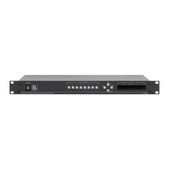
Page 7: Figure 1: Va-8Xl 8-Channel Balanced Stereo Audio Amplifier Front Panel
Figure 1: VA-8xl 8-Channel Balanced Stereo Audio Amplifier Front Panel Feature Function POWER Switch Illuminated switch supplying power to the unit CHANNEL SELECTOR Buttons (a). Select/deselect the stereo channel (from 1 to 8) (b). Select a setup number (from 1 to 15) DOWN (a). -
Page 8: Figure 2: Va-8Xl 8-Channel Balanced Stereo Audio Amplifier Rear Panel
Figure 2: VA-8xl 8-Channel Balanced Stereo Audio Amplifier Rear Panel Feature Function IN Terminal Block Connectors Connect to audio sources (from 1 to 8) OUT Terminal Block Connectors Connect to audio acceptors (from 1 to 8) RS-485 Detachable Terminal Block Port Pin # 1 is for Ground;... -
Page 9: Connecting The Va-8Xl
Connecting the VA-8xl Always switch off the power to each device before connecting it to your VA-8xl. After connecting your VA-8xl, connect its power and then switch on the power to each device. To connect the VA-8xl as illustrated in the example in Figure 1. -
Page 10: Figure 6: Connecting The Va-8Xl 8-Channel Balanced Stereo Audio Amplifier
Figure 6: Connecting the VA-8xl 8-Channel Balanced Stereo Audio Amplifier VA-8xl - Connecting the VA-8xl... -
Page 11: Operating The Va-8Xl
(stored in the non-volatile memory), showing the settings in the LED displays. After that, the VA-8xl goes to channel 1, and shows its gain/attenuation level in dB. During regular work, the VA-8xl shows the status of the last channel you observed and/or changed. To observe the status of a channel: •... -
Page 12: Storing And Recalling Setups
“YES” appears in the LEFT LED display and the setup number appears in the RIGHT LED display. Note: Saving a setup to an previously allocated setup number, overwrites the previous setup To cancel, press the LEFT or RIGHT button VA-8xl - Operating the VA-8xl... - Page 13 If no setting is stored in the non-volatile memory with that setup #, “NO” appears in the LEFT LED display and the setup number appears in the RIGHT LED display. Note: Recalling a setup implements the amplifier gain or the attenuation immediately VA-8xl - Operating the VA-8xl...
-
Page 14: Controlling The Va-8Xl
15 units via RS-485 or RS-232 (see Section 6.3). Controlling a Single VA-8xl Unit To connect and control a single VA-8xl unit, connect the following to the rear panel: • PC or other controller, see Section 6.2: “Preparing the RS-232... -
Page 15: Figure 8: Straight Cable Rs-232 Connection With A Null Modem Adapter
To control a unit via RS-232 or RS-485, each unit has to be identified via its unique MACHINE #. Set the MACHINE # on a VA-8xl unit according to the following table. A valid MACHINE # is from 1 to 15. -
Page 16: Configuring Up To A 120 Channel Balanced Stereo Audio Amplifier
For a single, stand alone machine, set as MACHINE # 1. MACHINE # DIP-SWITCH Configuring up to a 120 Channel Balanced Stereo Audio Amplifier To connect up to 15 VA-8xl units, do the following: • Connect the balanced/unbalanced audio sources/acceptors to the rear panel on each unit (see Section •... -
Page 17: Figure 10: Configuring Up To 15 Va-8Xl Units
To connect the control interface on a set of units, do one of the following: • Connect the RS-232 port on the first VA-8xl unit to a PC or other controller, and then connect the RS-232 port on each of the... -
Page 18: Figure 11: Preparing The Rs-232 Connectors
9 to PIN 2. 5. Connect the RS-232 9-pin D-sub (M) connector (B) to the RS-232 9-pin D-sub (F) port on the first VA-8xl unit. 6. Attach the RS-232 9-pin D-sub (M) connector (C) to another RS-232 9-pin D-sub (M) connector, if required, by connecting PIN 5 to PIN 5, PIN 8 to PIN 3, PIN 9 to PIN 2. - Page 19 To connect an RS-485 connector on one VA-8xl unit to an RS-485 connector on another unit: 1. Connect the “+” PIN on the first VA-8xl unit to the “+” PIN on the second VA-8xl unit 2. Connect the “-” PIN on the first VA-8xl unit to the “-” PIN on the second VA-8xl unit 3.
-
Page 20: Figure 12: An Rs-485 Control Interface Setup
Figure 12: An RS-485 Control Interface Setup VA-8xl - Controlling the VA-8xl... -
Page 21: Upgrading The Flash Memory
Before installing the latest Kramer firmware version on a VA-8xl unit, do the following: 1. Connect the RS-232 9-pin D-sub rear panel port on the VA-8xl unit to the null modem adapter and connect the null modem adapter with a 9-wire flat... -
Page 22: Upgrading Firmware
3. Connect the power cord and turn the POWER switch on the VA-8xl ON. The LED displays may show erratic data, which should be ignored. Upgrading Firmware Follow these steps to upgrade the firmware: 1. Double click the desktop icon: “Shortcut to FLIP.EXE”. -
Page 23: Figure 14: Atmel - Flip Window
4. Choose the file: “Va8xl.cfg” (by double-clicking it). If COM 2 was not selected (see Section 7.2), an RS-232 error message appears. In the “Atmel – Flip” window, the Operations Flow column is disabled, and crosses appear in the third column. VA-8xl - Upgrading the Flash Memory... -
Page 24: Figure 16: Atmel - Flip Window (Rs-232 Communication)
In the “Atmel – Flip” window, in the Operations Flow column, the Run button is active, and the name of the chip appears as the name of the third column: T89C51RD2. Verify that in the Buffer Information column, the “HEX File: Va8xl.hex” appears. VA-8xl - Upgrading the Flash Memory... -
Page 25: Figure 18: Atmel - Flip Window (Connected)
(see also the blue progress indicator on the status bar). When the operation is completed, all 4 check-boxes will be colored green and the status bar message: Memory Verify Pass appears: If an error message: “Not Finished” shows, click Run again. VA-8xl - Upgrading the Flash Memory... -
Page 26: Figure 19: Atmel - Flip Window (Operation Completed)
Figure 19: Atmel – Flip Window (Operation Completed) 8. Close the “Atmel – Flip” window. 9. Turn the POWER switch on the VA-8xl OFF. 10. Disconnect the RS-232 9-pin D-sub rear panel port on the VA-8xl unit from the null modem adapter. 11. Set DIP 7 OFF. -
Page 27: Technical Specifications
90 - 240V AC, 13VA DIMENSIONS: 19” x 7” x 1U (W, D, H) rack-mountable WEIGHT: 3.5kg (7.8lbs) approx. ACCESSORIES: Power cord, null modem adapter, Windows®-based control software Specifications are subject to change without notice at http://www.kramerelectronics.com VA-8xl - Technical Specifications... -
Page 28: Default Communication Parameters
Baud Rate: 9600 Data Bits: Stop Bits: Parity: None Command Format: Example (Output 1 to Input 1): 0x01, 0x81, 0x81, 0x81 Ethernet IP Address: 192.168.1.39 TCP Port Number: 5000 Network Mask: 255.255.255.0 Default Gateway: 192.168.1.1 VA-8xl - Default Communication Parameters... -
Page 29: Kramer Protocol 2000
channel In addition to the above, instructions 15, 18, 19, 20, 61, 62 (decimal) of Kramer’s Protocol 2000 are also fully implemented in the unit. For instructions 18 and 19, setups 01 to 15 (decimal) are valid. See the following examples:... -
Page 30: Hex Codes For Attenuation Gain Control
The following tables define the VA-8xl hex codes for attenuation gain control, amplification gain control and the channel number codes. 10.1 Hex Codes for Attenuation Gain Control Gain Hex Codes Gain Hex Codes Gain Hex Codes (dB) (dB) (dB) Mute... -
Page 31: Hex Codes For Amplification Gain Control
16 XX EA A1 +10.5 +10.5 16 XX D5 A1 +21.5 +21.5 16 XX EB A1 10.3 C hannel Number Codes 2 2 B Channel Left Right Both Channel Left Right Both (L & R) (L & R) VA-8xl - Kramer Protocol 2000... - Page 32 VA-8xl - Kramer Protocol 2000...
- Page 33 " " P/N: 2900- 300151 Rev: 1...
Need help?
Do you have a question about the VA-8xl and is the answer not in the manual?
Questions and answers