Advertisement
Quick Links
RF
USB R
TO
1. Kit Contents
The RF to USB Reference Design contains the following items:
EZRadioPRO
EZRadioPRO
AAA Battery
2. Introduction
The purpose of this reference design is to demonstrate a very low-power, wireless USB system. The system
consists of two components: a wireless Sensor Node and a USB Dongle. The Sensor Node uses a Silicon Labs
C8051F912 MCU and a Silicon Labs Si4431 radio. The Dongle uses a Silicon Labs C8051F342 MCU and a Silicon
Labs Si4431 radio.
The reference design includes two demo applications which implement some typical usage scenarios. The RF to
USB Network Demo shows how the Sensor Node can be used as a wireless sensor, periodically transmitting
remote sensor data back to the host PC. The RF to USB UART Demo shows how the Sensor Node can be used as
a wireless link, shuttling data between two systems.
The wireless Sensor Node and the USB Dongle are small, simple designs and easy to implement, enabling them to
be inexpensively and quickly added to any system that requires wireless capability. There are very few components
required other than the MCU and radio, and typically expensive components such as a wired antenna and external
voltage regulator are not required.
The wireless Sensor Node operates at 915 MHz and is powered by a single AAA battery and uses the on-chip dc-
dc converter of the C8051F912 to provide power for the EZRadioPRO
wireless Sensor Node is not transmitting or receiving data, it can remain in a low-power state where it only
consumes 50 nA. The power efficiency of the Sensor Node allows it to operate on a single cell battery for an
extended period of time. The estimated battery life is seven years, limited primarily by the self-discharge of the
battery.
Rev. 0.1 12/09
Arrow.com.
Downloaded from
EFERENCE
®
F912/4431 Sensor Node
®
F342/4431 Dongle
PC
Network
Demo
GUI
Dongle
Network
Dongle
App
UART
Dongle
App
Figure 1. System Diagram
Copyright © 2009 by Silicon Laboratories
R F - t o - U S B - R D
D
U
ESIGN
SER
®
UART
Demo
GUI
USB
HID
Bootloader
App
Firmware
Image
EZRadioPRO
'
G
S
UIDE
radio and the other components. When the
Node
Network
Node
App
UART
Node
App
EZRadioPRO
RF-to-USB-RD
Advertisement

Related Manuals for Silicon Laboratories EZRadioPRO F912/4431


Summary of Contents for Silicon Laboratories EZRadioPRO F912/4431
- Page 1 The estimated battery life is seven years, limited primarily by the self-discharge of the battery. Network UART Demo Demo Node Dongle Network Node Bootloader Network Dongle UART Firmware Node Image UART Dongle EZRadioPRO EZRadioPRO Figure 1. System Diagram Rev. 0.1 12/09 Copyright © 2009 by Silicon Laboratories RF-to-USB-RD Arrow.com. Downloaded from...
-
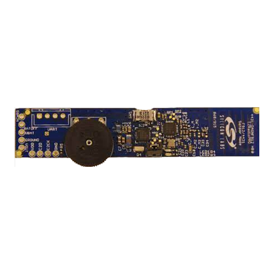
Page 2: Hardware Overview And Setup
RF-to-USB-RD 3. Hardware Overview and Setup Figure 2 and Figure 3 identify the major components of the Sensor Node and the USB Dongle. Both devices come preloaded with the firmware for the demo applications. When using the demo applications, ensure that the printed antenna on the wireless board is not covered by the user’s fingers. -
Page 3: Software Setup
PC. To run the demo, first ensure that the hardware is connected as described in “3. Hardware Overview and Setup” and the software is installed as described in “4. Software Setup”. 1. Launch the program, which is found by clicking StartAll ProgramsSilicon LaboratoriesRF to USB RDNetwork Demo. - Page 4 RF-to-USB-RD Figure 4. RF to USB Network Demo Application Initial Screen 5. Insert the AAA battery. If the battery has already been installed, please remove the AAA battery, press the button for at least one second to discharge the capacitor, release the button, then re-insert the battery. This will reset the MCU on the Sensor Node.
- Page 5 RF-to-USB-RD Figure 5. RF to USB Network Demo Application During Communication When the button on the Sensor Node is pressed to initiate communication with the USB Dongle, the Sensor Node obtains a Device ID. The Device ID is persistent as long as the Sensor Node is powered. If multiple Sensor Nodes are present, each of them will obtain a unique Device ID.
- Page 6 Release the button on the Sensor Node. The LEDs will blink quickly for 10 seconds or until the button is released. This step configures the Sensor Node to run the UART demo instead of the Network demo. 3. Launch the UART demo, which is found by clicking StartAll Programs Silicon LaboratoriesRF to USB RDUART Demo.
- Page 7 RF-to-USB-RD Figure 7. RF to USB UART Demo Application Initial Screen 5. Type an ASCII string in the Transmit text box and click on the Transmit button. This will send the string to the Sensor Node which will transmit it to the external device. If the device is configured for loopback mode, the transmitted data is sent back to the PC.
- Page 8 RF-to-USB-RD Figure 8. RF to USB UART Demo Application During Communication When the Sensor Node receives any UART data on the RX pin, it will wake from the low power mode and transmit data immediately. The Sensor Node also polls the USB Dongle once per second. If there is any data waiting, the Sensor Node will retrieve pending data.
-
Page 9: Additional Information
RF-to-USB-RD 7. Additional Information ® The RF to USB RD uses a 915 MHz RF link. The demo firmware is written on top of EZMAC PRO. The RF link data rate is 100 kbps using GFSK modulation. Both demo applications use EZMAC PRO channel 0. The output power is +13 dB for both the USB Dongle and Sensor Node. - Page 10 RF-to-USB-RD Rev. 0.1 Arrow.com. Arrow.com. Arrow.com. Arrow.com. Arrow.com. Arrow.com. Arrow.com. Arrow.com. Arrow.com. Arrow.com. Downloaded from Downloaded from Downloaded from Downloaded from Downloaded from Downloaded from Downloaded from Downloaded from Downloaded from Downloaded from...
- Page 11 RF-to-USB-RD Rev. 0.1 Arrow.com. Arrow.com. Arrow.com. Arrow.com. Arrow.com. Arrow.com. Arrow.com. Arrow.com. Arrow.com. Arrow.com. Arrow.com. Downloaded from Downloaded from Downloaded from Downloaded from Downloaded from Downloaded from Downloaded from Downloaded from Downloaded from Downloaded from Downloaded from...
- Page 12 RF-to-USB-RD Rev. 0.1 Arrow.com. Arrow.com. Arrow.com. Arrow.com. Arrow.com. Arrow.com. Arrow.com. Arrow.com. Arrow.com. Arrow.com. Arrow.com. Arrow.com. Downloaded from Downloaded from Downloaded from Downloaded from Downloaded from Downloaded from Downloaded from Downloaded from Downloaded from Downloaded from Downloaded from Downloaded from...
- Page 13 RF-to-USB-RD OTES Rev. 0.1 Arrow.com. Arrow.com. Arrow.com. Arrow.com. Arrow.com. Arrow.com. Arrow.com. Arrow.com. Arrow.com. Arrow.com. Arrow.com. Arrow.com. Arrow.com. Downloaded from Downloaded from Downloaded from Downloaded from Downloaded from Downloaded from Downloaded from Downloaded from Downloaded from Downloaded from Downloaded from Downloaded from Downloaded from...
-
Page 14: Contact Information
Silicon Laboratories products are not designed, intended, or authorized for use in applications intended to support or sustain life, or for any other application in which the failure of the Silicon Laboratories product could create a situation where per- sonal injury or death may occur.
Need help?
Do you have a question about the EZRadioPRO F912/4431 and is the answer not in the manual?
Questions and answers