
Subscribe to Our Youtube Channel
Related Manuals for Amada ST-100A


Summary of Contents for Amada ST-100A
- Page 1 ESISTANCE ELDING OLVED AC WELDER ST-100A ST-200A OPERATION MANUAL 990-351 Rev K 844-WSI-WELD ¥ +1-216-475-5629 www.WSIWELD.com ¥ ¥ 4943 Driscoll Road Warrensville Heights, OH 44146 USA...
- Page 2 Warrensville Heights, OH 44146 USA Copyright © 2001 - 2021 AMADA WELD TECH INC. The engineering designs, drawings and data contained herein are the proprietary work of AMADA WELD TECH and may not be reproduced, copied, exhibited or otherwise used without the written authorization of AMADA WELD TECH.
- Page 3 About This Equipment The ST-100A / 200A consists of a cabinet which contains; (1) an AC Main Timer Board, (2) SCR Driver Board, (3) Control Panel Assembly, (4) valve + power transformers, (5) SCR assemblies + snubbers and (6) surge resistors.
-
Page 4: Table Of Contents
Space and Mounting Requirements ....................2-1 Power Requirements ........................2-1 Cooling Water Requirements ......................2-1 Section II: Power Supply Set-up ......................2-2 Unpacking ............................2-2 Installation ............................2-2 Mounting the Power Supply ......................2-2 Connecting Electrical Power ......................2-2 ST-100A / ST-200A AC CONTROL... - Page 5 Valve Transformer Wiring Connections .................. 2-3 Cooling Water Hose Connections ....................2-3 Input / Output Signal Connections ....................2-3 Chapter 3. Using ST-100A / ST-200A Control Functions Section I: Overview ..........................3-1 Section II: Schedule Screen ........................3-2 SCHEDULE # ..........................3-2 PROGRAM/SAVE ..........................
- Page 6 BIN. SCHED. SELECT (Binary Schedule Select) ..............3-13 FIRING SWITCH ........................3-13 COIL ............................3-13 CONTRAST+/– ........................3-13 NUM VALVES (Number of Valves)..................3-14 VALVES STATUS ........................ 3-14 MODE ............................ 3-14 MORE (System Value Screen 2) .................... 3-14 ST-100A / ST-200A AC CONTROL...
- Page 7 HEAT% ............................3-19 Chapter 4. Operating Instructions Section I: Introduction ........................... 4-1 Overview ............................4-1 General Operator Safety ........................4-1 Section II: Preparing for Operation ......................4-2 Turning the Equipment ON ......................4-2 Pre-Operational Setup ........................4-3 ST-100A / ST-200A AC CONTROL...
- Page 8 Optional SCR Assembly, 600,1200, 1800, and 2200 Amp ............5-11 Section V. Spare Parts .......................... 5-12 Section VI. Repair ..........................5-13 Section VII. Storage and Shipment ...................... 5-13 Preparation for Storage or Shipment ..................... 5-13 Packing for Storage or Shipment ....................5-13 ST-100A / ST-200A AC CONTROL viii...
- Page 9 Appendix G. Voltage Monitor Board Option ................... G-1 Appendix H. Force Control Option....................H-1 Appendix I. Pressure Monitoring Option....................I-1 Appendix J. Communications Option ....................J-1 Appendix K. Circuit Modification for External Transformer Thermostat ........K-1 Appendix L. Default Initializations ....................L-1 ST-100A / ST-200A AC CONTROL...
- Page 10 Warrensville Heights, OH 44146 USA SAFETY NOTES This instruction manual describes how to operate, maintain and service the ST-100A / ST-200A AC Control / Power Supply, and provides instructions relating to its SAFE use. For SAFETY, and to effectively take advantage of the full capabilities of this Power Supply, please read these instructions before attempting to use the equipment.
- Page 11 1. Applicability. (a) These terms and conditions of sale (these “Terms”) are the only terms which govern the sale of the goods (“Goods”) by Amada Weld Tech Inc. (“Seller”) to the buyer identified in the Sales Quotation and/or Acknowledgment (as each defined below) to which these Terms are attached or incorporated by reference (“Buyer”).
- Page 12 Agreement. Buyer shall immediately discontinue use of the Software upon any termination of this license or Agreement. This license shall terminate upon any termination of the Agreement. ST-100A / ST-200A AC CONTROL...
- Page 13 FORESEEN BY BUYER, REGARDLESS OF THE LEGAL OR EQUITABLE THEORY (CONTRACT, TORT OR OTHERWISE) UPON WHICH THE CLAIM IS BASED, AND NOTWITHSTANDING THE FAILURE OF ANY AGREED OR OTHER REMEDY OF ITS ESSENTIAL PURPOSE. ST-100A / ST-200A AC CONTROL xiii...
- Page 14 Agreement when and to the extent such failure or delay is caused by or results from acts or circumstances beyond the reasonable control of Seller including, without limitation, acts of God, flood, fire, earthquake, explosion, governmental actions, war, invasion or hostilities ST-100A / ST-200A AC CONTROL...
- Page 15 27. Survival. Provisions of these Terms which by their nature should apply beyond their terms will remain in force after any termination or expiration of this Order including, but not limited to, the following provisions: Compliance with Laws, Confidentiality, Governing Law, Dispute Resolution, Survival, and the restrictions on Software in Sections 10(b), (c) and (d). ST-100A / ST-200A AC CONTROL...
-
Page 17: Section I: Features
Section I: Features Overview For the rest of this manual, ST-100A / ST-200A Single-Phase AC Welding Control will simply be referred to as the “Power Supply,” except in specific instances where unique descriptions are required such as specifications, connections, etc. In those instances ST-100A or ST-200A will be specified. The Power Supply has a wide variety of options, some are installed at the time of purchase and some may be added later. -
Page 18: Standard Features
NOTE: This feature requires presence of the Force Control (Force Output) board, but does not require usage of the Force Output feature in order for Force Input to be functional. ST-100A / ST-200A AC CONTROL... -
Page 19: Section Ii: Major Components
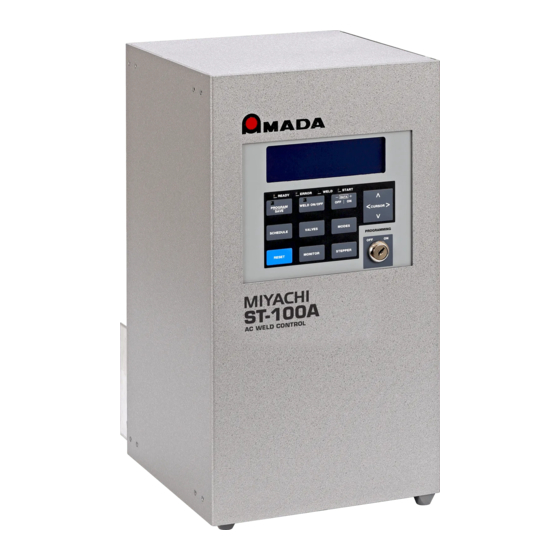
For example, the LCD Display and operating controls can be factory-installed on the front or on the side of the Power Supply. Dimensions and weight for each model are listed in Appendix A, Technical Specifications. ST-200A Major Components (Typical) ST-100A / ST-200A AC CONTROL... - Page 20 844-WSI-WELD ¥ +1-216-475-5629 www.WSIWELD.com ¥ ¥ 4943 Driscoll Road Warrensville Heights, OH 44146 USA CHAPTER 1: DESCRIPTION ST-100A Major Components (Typical) ST-100A / ST-200A AC CONTROL...
-
Page 21: Front Panel Controls And Indicators
ST- 200A Power Supply. ST-100A / ST-200A Controls and Indicators LCD Display White on blue 40 x 8 LCD display provides information for programming and monitoring the unit. -
Page 22: Weld On/Off
Weld2 Current High, Full Wave Conduction, Illegal Schedule Number, SCR shorted Pressing this pushbutton also resets minor errors if auto reset is turned . See Chapter 3, Section VIII, Using ST-100A / ST-200A Control Functions. Monitor When the pushbutton switch is set to... -
Page 23: Cursor
+ or – key of the pushbutton will cause the digit in that position to increment DATA or decrement by one digit. Programming This optional key lock prevents any change in the program when it is locked. Lock ST-100A / ST-200A AC CONTROL... -
Page 24: External Connectors
External connectors for Voltage Sensing, Current Sensing, Data & Communications (RS-232 or RS-485), and cooling water for the SCRs are on a panel that can be mounted on the top, bottom, or sides of the Power Supply. ST-100A / ST-200A AC CONTROL... -
Page 25: Cylinder Air Hose Connections
There are no operator adjustments inside of the unit, so the door should not need to be opened except for initial installation (electrical connections) and for repair of components. NOTE: If your unit is equipped with a circuit breaker, that breaker must be de-energized to open the door and access the components. ST-100A / ST-200A AC CONTROL... -
Page 26: Option Cards
Printed circuit boards (“cards”) for the ST-100A / ST-200A options can be installed in each Power Supply. The ST-100A has a card cage that can accept three option cards. The larger ST-200A models each have a card cage that can accept four option cards. Option boards can be inserted into a card cage in any order. -
Page 27: Environmental Factors
Maximum altitude 9,800 ft. (3,000 m) Space and Mounting Requirements Outline drawings of the ST-100A / ST-200A Power Supplies, including dimensions for the mounting holes, are included in Appendix A, Technical Specifications. Power Requirements Power requirements are: 230 or 460 VAC (nominal), single phase, 50/60 Hz. (See Appendix A, Technical Specifications, for exact ranges.) Other voltages are available upon request. -
Page 28: Section Ii: Power Supply Set-Up
Be sure all metallic shards are removed from the Power Supply after punching holes. Mounting the Power Supply The ST-100A is small and is commonly used standing on a bench, but can be machine-mounted using the detachable mounting tabs shipped with the Power Supply. -
Page 29: Secondary Current Sensing
Verify that the cooling water lines do not condense with moisture. If necessary, increase the external cooling water temperature to raise the dew point and prevent condensation. Input / Output Signal Connections Connect the input/output (I/O) signals as shown in the Appendix B, Electrical and Data Connections. ST-100A / ST-200A AC CONTROL... -
Page 31: Chapter 3. Using St-100A / St-200A Control Functions Section I: Overview
Before programming the Power Supply, you must be familiar with the location and function of the LCD and front panel controls. If you need more information on these controls, see Chapter 1, Description. Chapter 4, Operating Instructions, contains the step-by-step instructions on how to program each of the functions above. ST-100A / ST-200A AC CONTROL 990-351... -
Page 32: Section Ii: Schedule Screen
(weld power is not necessarily applied). It allows the system to settle and any mechanical motion or ringing to stop before welding begins. – This is the upslope time for weld 1 of the sequence. ST-100A / ST-200A AC CONTROL 990-351... -
Page 33: Co (Cool Time)
The time between each Weld 2 pulse is determined by the programmed time. ST-100A / ST-200A AC CONTROL 990-351... -
Page 34: Copy To # - Copying A Schedule
, COPY TO 10 PLUS 02 current schedule to schedules . The 10, 11 SCHEDULES HAVE BEEN COPIED following message will be displayed: PRESS ANY SCREEN KEY TO CONTINUE I.E. SCHEDULE, VALVES, MODES, OR MONITOR ST-100A / ST-200A AC CONTROL 990-351... -
Page 35: Section Iii: Valves Screen
, a valve will turn on at the start of the STATUS squeeze delay ( ). (See Appendix D, System Timing for details.) –This is a display-only field and allows the operator to view the weld count used in the COUNT Stepper function. ST-100A / ST-200A AC CONTROL 990-351... -
Page 36: Section Iv: Monitor Screen
Force is programmable from 1 to 9999 lb. A setting of 0000 is equivalent to the high monitor being off. See Chapter 4 Section V for a list of associated error messages. ST-100A / ST-200A AC CONTROL 990-351... -
Page 37: Counts (Monitor Counts Screen)
If not, the Power Supply will wait for about 5 seconds for acceptable pressure readings. If acceptable readings are not reached within that period, a minor error will be recorded. Counts -- This control takes you to the screen. MONITOR COUNTS ST-100A / ST-200A AC CONTROL 990-351... -
Page 38: Section V: Monitor Counts Screen
– Displays the current weld count of the step. This data is not programmable. When the STEP COUNT Stepper is off, is displayed. 0000 – This item displays the electrode valve number used with this schedule. The valve is ELECT. VALVE selected using the screen. Schedule ST-100A / ST-200A AC CONTROL 990-351... -
Page 39: Section Vi: Mode Screen
When the Start Start signal is released, , and will run to completion and the schedule will conclude with CO, UP2 times. (See Appendix D, System Timing for details.) ST-100A / ST-200A AC CONTROL 990-351... -
Page 40: Weld Mode
At the completion of the chain, monitor results may be viewed for each weld if WELD is turned and the key is used to increment / decrement the schedule number. ON/OFF DATA +/- ST-100A / ST-200A AC CONTROL 3-10 990-351... -
Page 41: Linked Sched
See Appendix D for a graphical representation of this weld mode. -- Placing the cursor at the symbol, and pressing the key will cause the Linked LINKED SCHED DATA+ Schedule screen to be displayed. ST-100A / ST-200A AC CONTROL 990-351 3-11... -
Page 42: Section Vii: Linked Schedules Screen
– This notification shall be displayed when a schedule number is repeated in the list. If it is ERROR desirable to use the same schedule in two different link sequences, copy the schedule and assign it a different schedule number. ST-100A / ST-200A AC CONTROL 3-12 990-351... -
Page 43: Section Viii: System Values Screens
– This Power Supply has no option; it is set for COIL By placing the cursor at the first character of this field and using the pushbutton, CONTRAST+/– – DATA +/– the operator can increase or decrease the contrast of the LCD screen. ST-100A / ST-200A AC CONTROL 990-351 3-13... -
Page 44: Num Valves (Number Of Valves)
– This control determines how the Power Supply reacts to an internal minor error signal. AUTO RESET When , an error signal will prevent the Power Supply from reacting to the next AUTO RESET Start signal and will inhibit an signal output from the Power Supply. ST-100A / ST-200A AC CONTROL 3-14 990-351... -
Page 45: Error Output
Welding is not allowed when the weld head is retracted. The mode requires the input switch to PULSED be toggled before the output changes state. Welding is not allowed when the weld head is retracted. ST-100A / ST-200A AC CONTROL 990-351 3-15... -
Page 46: Pressure Switch
The psi setting for this parameter will only be accurate if the electronic pressure regulator has the association of 0 – 10 VDC = 0 – 100 psi. Returns you to Screen 2 SYSTEM VALUES SCREEN2. ST-100A / ST-200A AC CONTROL 3-16 990-351... -
Page 47: Section Ix. System Valve Status Screen
– This column indicates the SCR used with each valve. It can be programmed from 1 to the maximum number of SCRs selected at the screen. If desired, it can also be programmed to System Wide Values (not applicable). ST-100A / ST-200A AC CONTROL 990-351 3-17... -
Page 48: Section X: Force Calibration Screen
The Valve # must be programmed with the valve that is being turned on to create the weld force. The PSI value at the top left of the screen indicates the actual differential pressure across the weld head cylinder for the active channel if the force input option is installed. ST-100A / ST-200A AC CONTROL 3-18 990-351... -
Page 49: Section Xi. Stepper Screen
100% of the weld current set in the schedule. All other fields are programmable from 50% to 200%. If the setting is 100%, the weld current will be that set in the schedule. Example of Stepper Function ST-100A / ST-200A AC CONTROL 990-351 3-19... -
Page 51: Chapter 4. Operating Instructions
The location and function of Controls and Indicators. For more information, see Chapter 1 of this manual. How to select and use the Power Supply functions for your specific welding applications. For more information, see Chapter 3, Using ST-100A / ST-200A Control Functions. General Operator Safety WARNINGS To prevent blindness or eye injury, wear safety goggles at all times during welding. -
Page 52: Section Ii: Preparing For Operation
ST RESISTANCE WELDING SYSTEM installed in the Power Supply. If you ever need to AMADA WELD TECH contact AMADA WELD TECH for technical MONROVIA, CALIFORNIA assistance, Customer Support will need to know COPYRIGHT 2020, ALL RIGHTS RESERVED which version (“Release”) number of the software... -
Page 53: Pre-Operational Setup
Following this section is a display of information and error screens, which you might encounter during set-up. ST-100A / ST-200A AC CONTROL 990-351... -
Page 54: Section Iii: Setup Messages
You may receive one of the following messages during set-up of the Power Supply. The message tells you what corrective action should be taken. If you cannot correct the action by performing these instructions, contact your AMADA WELD TECH representative. SCHEDULE 01 WELD 1 CURRENT LESS THAN 20% OF SYSTEM FULL CURRENT. - Page 55 The FORCE value on the SCHEDULE screen Must be greater than the FORCE LO and less than the FORCE HI values on the MONITOR screen. Also, FORCE must be equal to or greater than the MONITOR screen FORCE FIRING value. ST-100A / ST-200A AC CONTROL 990-351...
-
Page 56: Section Iv. Operation
During welding operation, you may monitor the operation of the Power Supply through the various screens described in Chapter 3, Using ST-100A / ST-200A Controls, but you cannot modify the schedules. If your unit has a PROGRAMMING lock, you will be unable to change the schedules unless programming is turned ON. -
Page 57: Spot Welds
Power Supply into the LOCAL MODE WELD ON/OFF ready to weld mode. The green LED in the button will turn ON. WELD ON/OFF 12 Actuate the Start signal to begin welding. ST-100A / ST-200A AC CONTROL 990-351... -
Page 58: Continuous Seam Weld
¥ 4943 Driscoll Road Warrensville Heights, OH 44146 USA CHAPTER 4: OPERATING INSTRUCTIONS Continuous Seam Weld (ST-100A and ST-200A Option) To change the information in the schedule screen, the Power Supply must be in mode. PROGRAM From the schedule screen, press the... -
Page 59: Cascading (Multiple Scrs)
Use the + or – keys to turn each valve on or off in that schedule. 12 Use the screen to set welding limits (see Chapter 3, Using ST-100A / ST-200A Control MONITOR Functions, Section IV). - Page 60 This sets the first schedule in the chain. To help the user PROGRAM/SAVE follow which schedules are Linked together, AMADA WELD TECH has provided an easy to understand Help-Link. The -Link is located in the upper right-hand corner of the...
-
Page 61: Section V: Operational Messages
You may receive one of the following error messages during set-up or operation of the Power Supply. The message tells you what corrective action should be taken. If you cannot correct the action by performing these instructions, contact your AMADA WELD TECH representative. Major errors require pressing the button or giving a signal to the input to clear the error. - Page 62 3. PUSH RESET TO CONTINUE WITH THIS SCHEDULE (AND REDISPLAY THIS MSG). ** IMPROPER SCHEDULE NUMBER DETECTED ** FOUND AN OUT OF RANGE SCHEDULE NUMBER. VALID NUMBERS ARE 00 – 63. PRESS THE RESET KEY AND CONTINUE. ST-100A / ST-200A AC CONTROL 4-12 990-351...
-
Page 63: Minor Run-Time Error Messages
PRESS RESET BUTTON TO RESUME WELDING. WELD COUNT REACHED WELD COUNT LIMIT. IMPLEMENT USER DEFINED PROCEDURE FOR THIS CONDITION. AT THE MONITOR SCREEN: 1. SET WELD COUNT=0 OR 2. INCREASE WELD COUNT LIMIT. ST-100A / ST-200A AC CONTROL 990-351 4-13... - Page 64 *** ADVISORY MESSAGE ONLY *** HIGH LINE VOLTAGE WAS DETECTED. CHECK LINE VOLTAGE AND PRESS RESET KEY TO CONTINUE *** SCALE CURRENT ERROR *** SCALED CURRENT WAS GREATER THAN MAX. PRESS RESET KEY TO CONTINUE ST-100A / ST-200A AC CONTROL 4-14 990-351...
-
Page 65: Section Vi: Shutdown
The Power Supply will re-boot following the signal. Set the Power Supply to the desired RESET schedule. Normal Shutdown Turn off power from the external, customer-supplied circuit breaker or power contactor. ST-100A / ST-200A AC CONTROL 990-351 4-15... -
Page 67: Chapter 5. Maintenance Section I: Precautions
Other than as indicated in Appendix K, Circuit Modification for External Transformer Thermostat, do not modify the unit without prior written approval from AMADA WELD TECH. Use the appropriate tools for terminating the connecting cables, being careful not to nick the wire conductors. -
Page 68: Fuse Replacement
If there is only one SCR, the signal goes directly from the Main Board to the SCR Driver. The SCR Driver Board, in turn, causes the SCRs to switch the input voltage (L1) across the two surge resistors to the weld transformers. The snubber across the SCR assembly cancels inductive-kickback from the weld transformers. ST-100A / ST-200A AC CONTROL 990-351... -
Page 69: Wiring Diagram
CHAPTER 5: MAINTENANCE Simplified Block Diagram Wiring Diagram The diagram on page 5-4 shows the point-to-point wiring, which will assist you in performing continuity checks on the Power Supply or rewiring it after a repair. ST-100A / ST-200A AC CONTROL 990-351... - Page 70 844-WSI-WELD ¥ +1-216-475-5629 www.WSIWELD.com ¥ ¥ 4943 Driscoll Road Warrensville Heights, OH 44146 USA CHAPTER 5: MAINTENANCE ST-100A / ST-200A AC CONTROL 990-351...
-
Page 71: Section Iii. Standard Components Replacement
Two-wire cable from the primary current sensor or the secondary current sensor connector connected to J11. Two-wire cable from the Valve Expansion Card connected to J16 and the 26-wire ribbon cable from the same circuit board connected to J5. ST-100A / ST-200A AC CONTROL 990-351... - Page 72 Eight-wire connector from SCR Drive Board or Cascade Board to J15. Thirty-four-wire ribbon cable from Control Panel Assembly to J4. Four-wire cable (six-pin connector) from power transformer to J19 and seven-wire cable (eight pin connector) from power transformer to J17. ST-100A / ST-200A AC CONTROL 990-351...
-
Page 73: Power Transformer T1
To replace a surge resistor assembly, disconnect the violet wire from the SCR and the gray wire from Valve Transformer terminal H4. Remove the four screws and lock washers that attach the surge resistor assembly to the Power Supply chassis. ST-100A / ST-200A AC CONTROL 990-351... -
Page 74: Snubber
Reconnect the following cable connectors to the indicated headers on the circuit board: Six-wire cable (ten pin connector) from the SCR to J2. Eight-wire cable from AC Timer Main Board to J1 or Cascade Board. ST-100A / ST-200A AC CONTROL 990-351... -
Page 75: Control Panel Assembly
Thirty-four-wire ribbon cable connector from the AC Timer Main Board to J2. (Optional) two-wire cable connector from control panel key switch to J3. Install the protective cover plate over the Control Panel Assembly with four screws. ST-100A / ST-200A AC CONTROL 990-351... -
Page 76: Section Iv. Optional Components Replacement
Install or re-install the connector assembly by attaching it to the bottom of the Power Supply with the attaching hardware (nut and washer) supplied with the assembly. Reconnect the two-wire (black and red) cable connector to the AC Timer Main Board connector J11. ST-100A / ST-200A AC CONTROL 5-10 990-351... -
Page 77: Optional Key Lock
9 Reconnect the cooling water hoses to the SCR assembly on the bottom of the Power Supply chassis. 10 Turn on the water supply to the cooling hoses going to the SCR assembly. Check for leaks. ST-100A / ST-200A AC CONTROL 990-351 5-11... -
Page 78: Section V. Spare Parts
CHAPTER 5: MAINTENANCE Section V. Spare Parts Below is a list of frequently required spare parts, which can be obtained by contacting your AMADA WELD TECH representative. Additional parts are available by contacting AMADA WELD TECH using the phone, e-mail, or mailing information in the Foreword of this manual. -
Page 79: Section Vi. Repair
Using shop air, dry out the water-cooling chamber of the SCR. Remove the Power Supply from its mounting location. Packing for Storage or Shipment Repack the Power Supply into the original packing materials and packing box in which you originally received the unit. ST-100A / ST-200A AC CONTROL 990-351 5-13... -
Page 81: Appendix A. Technical Specifications
Load Power Factor 30 – 70%, fixed impedance Applicable Set Point 20 – 95% of current at 180° conduction angle. (Unit will operate outside these ranges, but Ranges accuracy and regulation specifications will not apply.) ST-100A / ST-200A AC CONTROL 990-351... - Page 82 *Inductive load regulation 2% of set point for 15% load induction fluctuation *Average Current Accuracy 1% of set point of full scale after initial response *For welds between 20% and 95% of full current ST-100A / ST-200A AC CONTROL 990-351...
- Page 83 844-WSI-WELD ¥ +1-216-475-5629 www.WSIWELD.com ¥ ¥ 4943 Driscoll Road Warrensville Heights, OH 44146 USA APPENDIX A: TECHNICAL SPECIFICATIONS Outline Drawings NOTE: Measurements are in inches (mm). ST-100A AC Control ST-100A / ST-200A AC CONTROL 990-351...
- Page 84 844-WSI-WELD ¥ +1-216-475-5629 www.WSIWELD.com ¥ ¥ 4943 Driscoll Road Warrensville Heights, OH 44146 USA APPENDIX A: TECHNICAL SPECIFICATIONS ST-200A AC Control ST-100A / ST-200A AC CONTROL 990-351...
-
Page 85: Appendix B. Electrical And Data Connections
C, SCR, Wire Gauge, and Circuit Breaker Selection.) Make sure you know how to make the connections. Emergency Stop Power and signal connections are made through the customer-provided punch-out holes in the Power Supply. ST-100A / ST-200A AC CONTROL 990-351... - Page 86 L2, and ground. If you do not have terminal block L2, connect the incoming L2 wire to H2-1 and H2-2, and connect an 18-gauge wire from there to H4 of the valve transformer. ST-100A / ST-200A AC CONTROL 990-351...
- Page 87 Input signals are referenced to either an internal or external 24 VDC power supply. NOTES: If you have an optional Valve Expansion Board, also make the output connections to that board, as shown on page B-7. Descriptions of these signals follow each diagram. ST-100A / ST-200A AC CONTROL 990-351...
- Page 88 844-WSI-WELD ¥ +1-216-475-5629 www.WSIWELD.com ¥ ¥ 4943 Driscoll Road Warrensville Heights, OH 44146 USA APPENDIX B: ELECTRICAL AND DATA CONNECTIONS Input / Output Control Signals ST-100A / ST-200A AC CONTROL 990-351...
- Page 89 SPR1/SPR1C – Weld On/Off Status This output indicates the NW1 status. (See ) When the output is closed, the unit is ready to weld. NOTE: These outputs are isolated contact relays that are closed when active. ST-100A / ST-200A AC CONTROL 990-351...
- Page 90 , saving any changes to the schedule or settings on the front panel will set the Power REMOTE Supply to the state. This input must then be opened and re-closed to set the state. Weld Off Weld On ST-100A / ST-200A AC CONTROL 990-351...
- Page 91 Output signals to drive up to eight additional valves. Each set of connections provides 115 VAC (standard) or 24 VAC (optional) power to the valve solenoid connected across those connections. Output is limited to 1 amp per channel. ST-100A / ST-200A AC CONTROL 990-351...
- Page 92 844-WSI-WELD ¥ +1-216-475-5629 www.WSIWELD.com ¥ ¥ 4943 Driscoll Road Warrensville Heights, OH 44146 USA...
-
Page 93: Appendix Cscr, Wire Gauge, And Circuit Breaker Selection
Max kVA Continuous Continuous Current Current Weld Demand Demand Demand Current (A) Current (A) Demand (A) Rating Current Rating (A) 1,100 1,200 1,800 1,250 1,250 1,800 2,500 2,083 1,000 2,083 2,200 3,200 2,430 1,166 2,430 ST-100A / ST-200A AC CONTROL 990-351... - Page 94 2 x 250 2 x 300 2 x 500 1,031 1,179 2 x 4/0 1,473 2 x 250 2 x 300 2 x 400 2 x 500 1,031 1,179 1,326 1000 1,473 1200 1,768 ST-100A / ST-200A AC CONTROL 990-351...
- Page 95 844-WSI-WELD ¥ +1-216-475-5629 www.WSIWELD.com ¥ ¥ 4943 Driscoll Road Warrensville Heights, OH 44146 USA APPENDIX C: SCR, WIRE GAUGE, AND CIRCUIT BREAKER SELECTION Wire Gauges Based on Demand (kVA) For wire gauge needed to support a maximum of 5% voltage drop, consult table C-4. The information herein is based on NFPA70 National Electric Code table 9 in Chapter 9.
- Page 96 3.840 x 10 1.226 x 10 1000 2,083 1.152 x 10 3.456 x 10 1.103 x 10 2 x 250 1200 2,500 9.600 x 10 2.880 x 10 9.195 x 10 2 x 300 ST-100A / ST-200A AC CONTROL 990-351...
-
Page 97: Appendix D. System Timing
Input and Output Timing Signals Figure D-1 shows the timing signals for the pulsed, latched, and maintained start signals. Table D-1 is the binary input for the schedules. Pulsed, Latched, and Maintained Start Signals ST-100A / ST-200A AC CONTROL 990-351... - Page 98 844-WSI-WELD ¥ +1-216-475-5629 www.WSIWELD.com ¥ ¥ 4943 Driscoll Road Warrensville Heights, OH 44146 USA APPENDIX D: SYSTEM TIMING Continuous Seam Weld ST-100A / ST-200A AC CONTROL 990-351...
- Page 99 The microprocessor requires up to 70 ms of calculation time upon closure of FS1 and 50 ms of calculation of FS2. Valves and current may have a different calculation time. Roll Spot Seam Weld ST-100A / ST-200A AC CONTROL 990-351...
- Page 100 844-WSI-WELD ¥ +1-216-475-5629 www.WSIWELD.com ¥ ¥ 4943 Driscoll Road Warrensville Heights, OH 44146 USA APPENDIX D: SYSTEM TIMING Spot Welding ST-100A / ST-200A AC CONTROL 990-351...
- Page 101 The microprocessor requires up to 70 ms of calculation time upon closure of FS1 and 50 ms of calculation of FS2. Valves and current may have a different calculation time. Spot Welding with 3 Impulses ST-100A / ST-200A AC CONTROL 990-351...
- Page 102 Sched A Sched B Sched C Sched A Chained Initiation required only once at beginning. Control defaults to first schedule start signal for all linked schedules. Early release aborts in Maintained Mode. Linked Schedules ST-100A / ST-200A AC CONTROL 990-351...
- Page 103 Schedule 47 Schedule 48 Schedule 49 Schedule 50 Schedule 51 Schedule 52 Schedule 53 Schedule 54 Schedule 55 Schedule 56 Schedule 57 Schedule 58 Schedule 59 Schedule 60 Schedule 61 Schedule 62 Schedule 63 ST-100A / ST-200A AC CONTROL 990-351...
- Page 104 844-WSI-WELD ¥ +1-216-475-5629 www.WSIWELD.com ¥ ¥ 4943 Driscoll Road Warrensville Heights, OH 44146 USA...
-
Page 105: Appendix E. Cascade Board Option
Reconnect the 8-wire cable connectors from each of the SCR Driver Boards to J4 through J7 as required. Reconnect the 2-wire power connector to J8. Cascade Board Connector Locations Slide the board into the card cage. ST-100A / ST-200A AC CONTROL 990-351... -
Page 107: Appendix F. Valve Expansion Board Option
(J2A and J2B). See the next illustration (Valve Expansion Board Output AC Main Timer AC Main Timer Signals) for a detailed listing of signals. Slide the card out of the card cage. Valve Expansion Board Connector Locations ST-100A / ST-200A AC CONTROL 990-351... - Page 108 Reconnect the 26-wire ribbon cable connector from the AC Timer Main Board to J3 Reconnect the 2-wire cable connector from the AC Timer Main Board to J1. Reconnect the I/O pluggable terminal strips to the board (J2A and J2B). Slide the card into the card cage. ST-100A / ST-200A AC CONTROL 990-351...
-
Page 109: Appendix G. Voltage Monitor Board Option
Voltage Measurement Range: Accuracy: +/- 2% of full scale Operation Voltage Monitor functions are described in Chapter 3,Using ST-100A / ST-200A Control Functions. Maintenance/Replacement Disconnect the serial cable connector (26-pin ribbon cable) connected to J10 on the Voltage Board. Disconnect the voltage sensing cables from V1 through V4 on the Voltage Board as required. - Page 111 Input the valve F2 0000 0001 F6 0000 0001 F3 0000 0001 F7 0000 0001 number that supplies air to the head to be F4 0000 0001 F8 0000 0001 calibrated. ST-100A / ST-200A AC CONTROL 990-351...
-
Page 112: Appendix H. Force Control Option
Reconnect the force input cables from J1 and the force output cables from J2 and J3 on the Force Output Board as required. Reconnect the serial cable connector (26-pin ribbon cable) to J10 on the Force Board. Install or re-install the circuit board by sliding it into the card cage. ST-100A / ST-200A AC CONTROL 990-351... -
Page 113: Appendix I. Pressure Monitoring Option
Board using a ribbon cable. As shown on the right, multiple Pressure Boards may be plugged Linked Pressure Boards into each other, then plugged into the ribbon cable because the signal passes through all the boards. ST-100A / ST-200A AC CONTROL 990-351... - Page 114 Input the valve F2 0000 0001 F6 0000 0001 F3 0000 0001 F7 0000 0001 number that supplies air to the head to be F4 0000 0001 F8 0000 0001 calibrated. Move the cursor to Lo-Psi. ST-100A / ST-200A AC CONTROL 990-351...
- Page 115 Calibration for this Channel is now PROGRAM/SAVE complete. 16 Example: As shown above on the right, Low Pressure was , High Pressure was 119 lb. 364 lb Repeat Steps 3-13 to calibrate other channels. ST-100A / ST-200A AC CONTROL 990-351...
- Page 116 Install the air hoses on the Pressure Board that were removed in Step 1. Install the new Pressure Board(s) either by plugging into the Force Board, or mounted separately and connected with a ribbon cable. ST-100A / ST-200A AC CONTROL 990-351...
-
Page 117: Appendix J. Communications Option
Section II. Communications Protocol and Commands. Using these codes, users can write customized software for controlling all functions of the Power Supply and interfacing the unit to automation control systems. ST-100A / ST-200A AC CONTROL 990-351... - Page 118 (total number of bytes exchanged per weld) (times) (8 bits per byte) must in all cases remain less than the theoretical maximum capacity of the channel – 38,400 bits per second. This capacity is not an issue on RS-232 channels. ST-100A / ST-200A AC CONTROL 990-351...
- Page 119 Several commands require the Power Supply to be in HOST mode for the Power Supply to accept them. Those commands include the REPORT command and all SET commands. See the HOST CNTL command in Chapter 3, Using ST-100A / ST-200A Control Functions and the REMOTE command in the next Section for more information.
- Page 120 ‘8’ Output timeout Valid Commands A valid command will return either data or <ACK> (0x06). <soh> <@> <ACK> <cksum> <eot> Data will be returned with the following structure: <soh> <@> <cmd> <cnt> <data> <cksum> <eot> ST-100A / ST-200A AC CONTROL 990-351...
- Page 121 3 Bytes Total TIME CLK “RT” Set <data>=0 Reset Time Clock 1 Byte “RT” Read <data>=1 Read Time Offset 1 Byte LINK “KR” Read none 0 Bytes “KS” Set SCHEDULE #, SCHEDULE #,… 64 Bytes ST-100A / ST-200A AC CONTROL 990-351...
- Page 122 (Energy 0 - 80.0 kA), See NOTE [1] 2 Bytes IMPULSE (0 - 25) 1 Byte FORCE, (0 - 9999) 2 Bytes FORCE CHANNEL (1 - 8) 1 Byte 35 Bytes Total NOTE [1]: 1,000 = 10.0 kA ST-100A / ST-200A AC CONTROL 990-351...
- Page 123 27 Bytes Total ------------------------------------------------------------------------- start value: MAINTAINED = 0 PULSED = 1 LATCHED = 2 SEAM = 3 ------------------------------------------------------------------------- weld mode: SPOT = 0 REPEAT = 1 SUCCESSIVE = 2 CHAINING = 3 ------------------------------------------------------------------------- ST-100A / ST-200A AC CONTROL 990-351...
- Page 124 {ON=1 | OFF=0} 1 Byte VALVE 9 {ON=1 | OFF=0} 1 Byte VALVE 10 {ON=1 | OFF=0} 1 Byte VALVE 11 {ON=1 | OFF=0} 1 Byte VALVE 12 {ON=1 | OFF=0} 1 Byte 14 Bytes Total ST-100A / ST-200A AC CONTROL 990-351...
- Page 125 SCR# Count 5 Bytes Valve 11 SCR# Count 5 Bytes Valve 12 SCR# Count 5 Bytes (1 - 8) (0 - 99999) 60 Bytes Total NOTE: SCR# = 1 Byte COUNT = 4 Bytes ST-100A / ST-200A AC CONTROL 990-351...
- Page 126 % Heat = 2 % Heat Secondary = 3 ------------------------------------------------------------------------- seam mode: Spot = 0 Continuous Seam = 1 Roll Spot = 2 (Seam welding is an optional feature) ------------------------------------------------------------------------- NOTE [1]: 1,000 = 10.0 kA ST-100A / ST-200A AC CONTROL J-10 990-351...
- Page 127 P4 ASSOCIATED VALVE #, 1 Byte P5 ASSOCIATED VALVE #, 1 Byte P6 ASSOCIATED VALVE #, 1 Byte P7 ASSOCIATED VALVE #, 1 Byte P8 ASSOCIATED VALVE #, 1 Byte 40 Bytes Total ST-100A / ST-200A AC CONTROL 990-351 J-11...
- Page 128 Read Time Offset in cycles since power-up or reset 4 Bytes “RT” Set <ACK> OR <NAK> 0 Bytes LINK “KS” Set <ACK> OR <NAK> 0 Bytes “KR” Read SCHEDULE #, SCHEDULE #,… 64 Bytes ST-100A / ST-200A AC CONTROL J-12 990-351...
- Page 129 See NOTE [1] 2 Bytes IMPULSE (0 - 25) 1 Byte FORCE, (0 - 9999) 2 Bytes FORCE CHANNEL (1 - 8) 1 Byte 35 Bytes Total NOTE [1]: 8,000 = 80.0 kA ST-100A / ST-200A AC CONTROL 990-351 J-13...
- Page 130 Stepper, 0 = No change, Valve # if changed 1 Byte Link Array 0 = No change, 1=change 1 Byte Active screen number 1 Byte Active screen value 1 Byte 9 Bytes Total ST-100A / ST-200A AC CONTROL J-14 990-351...
- Page 131 Run screen Stepper screen Weld mode screen % heat monitor screen Valve screen for 12 valves Not used Program screen for constant current modes System values screen Linked schedules screen Not used Not used ST-100A / ST-200A AC CONTROL 990-351 J-15...
- Page 132 Weld count reached limit error screen Stepper end reached error screen Not used Simplified schedule screen Simple % heat screen Not used Seam weld in primary current control screen Seam weld in % heat mode screen ST-100A / ST-200A AC CONTROL J-16 990-351...
- Page 133 Schedule W1 and W2 times set to 0 error screen Pixel test info screen Not used Not used Second hidden screen Incorrect SCR number detected screen Pressure switch error Force calibration screen System boot-up screen ST-100A / ST-200A AC CONTROL 990-351 J-17...
- Page 134 1 Byte VALVE 10 {ON=1 | OFF=0} 1 Byte VALVE 11 {ON=1 | OFF=0} 1 Byte VALVE 12 {ON=1 | OFF=0} 1 Byte 14 Bytes Total <ACK> OR <NAK> SCR's “UR” Read 0 Bytes ST-100A / ST-200A AC CONTROL J-18 990-351...
- Page 135 SCR # Count 5 Bytes Valve 10 SCR # Count 5 Bytes Valve 11 SCR # Count 5 Bytes Valve 12 SCR # Count 5 Bytes (1 - 8) (0 - 99999) 60 Bytes Total ST-100A / ST-200A AC CONTROL 990-351 J-19...
- Page 136 % Heat Primary = 1, Secondary C. Current = 2 % Heat Secondary = 3 % Heat = 4 ------------------------------------------------------------------------- seam mode: Spot = 0 Continuous Seam = 1 Roll Spot = 2 ------------------------------------------------------------------------- ST-100A / ST-200A AC CONTROL J-20 990-351...
- Page 137 P4 ASSOCIATED VALVE #, 1 Byte P5 ASSOCIATED VALVE #, 1 Byte P6 ASSOCIATED VALVE #, 1 Byte P7 ASSOCIATED VALVE #, 1 Byte P8 ASSOCIATED VALVE #, 1 Byte 40 Bytes Total ST-100A / ST-200A AC CONTROL 990-351 J-21...
- Page 138 Reconnect the 26-pin ribbon cable connector from the AC Timer Main Board to (coming from the external 9-pin connector) Reconnect the serial cable connector (coming from the external 9-pin connector) to J3. Slide the board into the card cage. ST-100A / ST-200A AC CONTROL J-22 990-351...
-
Page 139: Appendix K. Circuit Modification For External Transformer Thermostat
, and the socket terminal for the other side of the relay coil. Timer Main Board, A1 Carefully check all wiring and plug the relay into the relay socket. ST-100A / ST-200A AC CONTROL 990-351... - Page 141 Up 2 Time Weld 2 Time Down 2 Time Hold Time OFF Time Weld 1 Current 00.0 Weld 2 Current 00.0 Weld Valve ELECTRODE VALVE SCR Number SCR # Impulse IMPULSE Detailed Schedule Screen Detailed ST-100A / ST-200A AC CONTROL 990-351...
-
Page 142: Appendix L. Default Initializations
W1 – COND. LIMIT Weld 2 Current W2 – CURR 00.0 Weld 2 High Current Limit W2 – HIGH Weld 2 Low Current Limit W2 – LOW Weld 2 Conduction Angle Limit W2 – COND. LIMIT ST-100A / ST-200A AC CONTROL 990-351... - Page 143 Step 5 Heat % HEAT% 110% Step 6 Heat % HEAT% 120% Step 7 Heat % HEAT% 125% Step 8 Heat % HEAT% 125% Step 9 Heat % HEAT% 125% Step 10 Heat % HEAT% 125% ST-100A / ST-200A AC CONTROL 990-351...
- Page 145 TEL. +1-626-303-5676 FAX, +1-626-358-8048 http://www.amadaweldtech.com AMADA WELD TECH CO., LTD. 200, Ishida, Isehara-shi, Kanagawa 259-1196, Japan AMADA WELD TECH KOREA CO., LTD. 28, Dongtanhana 1-gil, Hwaseong-si, Gyeonggi-do, 18423, Korea TEL. +82-31-8015-6810 FAX. +82-31-8003-5995 AMADA WELD TECH SHANGHAI CO., LTD. Unit 401, A206(C8), No. 77, Hongcao Road, Xuhui District, Shanghai, China TEL.
- Page 146 Contact your WSI Representative TODAY! 844-WSI-WELD ESISTANCE ELDING OLVED www.WSIWeld.com ¥ sales@wsiweld.com DISTRIBUTED BY: 4943 Driscoll Road ¥ Warrensville Heights, OH 44146 USA Main: 844-44-TECNA ¥ International: +1-216-475-5629 Spot | Projection | Seam | Butt | Capacitor Discharge Resistance / MIG / TIG / Plasma Automation & Robotics Consumables | Accessories | Engineering | Service ®...
Need help?
Do you have a question about the ST-100A and is the answer not in the manual?
Questions and answers