Amada 301H/115V Operation Manual

Amada 301H/115V Operation Manual

Electronic weld head control
Table of Contents

Advertisement

ELECTRONIC WELD HEAD CONTROL
300 Series
OPERATION MANUAL
990-115 REV Q

Advertisement

Table of Contents
loading
Need help?

Need help?

Do you have a question about the 301H/115V and is the answer not in the manual?

Questions and answers

Summary of Contents for Amada 301H/115V

  • Page 1 ELECTRONIC WELD HEAD CONTROL 300 Series OPERATION MANUAL 990-115 REV Q...
  • Page 2 Copyright © 1990, 2002, 2007, 2013-2017 Amada Miyachi America The engineering designs, drawings and data contained herein are the proprietary work of AMADA MIYACHI AMERICA and may not be reproduced, copied, exhibited or otherwise used without the written authorization of AMADA MIYACHI AMERICA.
  • Page 3 Should questions arise, or if you have suggestions for improvement of this manual, please contact us at the above location/numbers. Amada Miyachi America is not responsible for any loss due to improper use of this product. SERIES 300 FAST RESPONSE WELD HEAD SYSTEM...
  • Page 4 SAFETY NOTES This instruction manual describes how to operate, maintain and service the Series 300 Fast Response Weld Head System, and provides instructions relating to its SAFE use. Procedures described in this manual MUST be performed, as detailed, by QUALIFIED and TRAINED personnel. For SAFETY, and to effectively take advantage of the full capabilities of the tester, please read these instruction manuals before attempting to use the workstation.
  • Page 5: Table Of Contents

    CONTENTS Page Chapter 1: Description Section I. Features ..........................1-1 Overview ............................1-1 Performance Features ........................1-1 Programmable Follow-Up Force ....................1-1 Weld-to-Displacement ......................1-2 Weld Head Dynamics ....................... 1-2 Other Important Features ......................1-2 Section II. Components
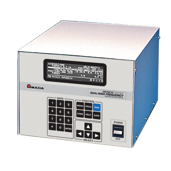
 .......................... 1-3 Equipment Description ........................
  • Page 6 Page Chapter 3: Operating Instructions Overview of the Series 300 (Metric) Weld Head Operation ..............3-1 The HELP Screens ........................... 3-3 A Closer Look at the PROGRAM Screens ..................3-3 Alphanumeric PROGRAM Screen ................... 3-4 UPST Position PROGRAM Screen ..................3-4 SRCH Position PROGRAM Screen ..................
  • Page 7 CONTENTS (Continued) Page Section V. Calibration ..........................4-6 Series 300 Weld Head System with the 350C Weld Head Control Applicable Models ....4-6 Equipment Required ........................4-6 Preliminary Setup ..........................4-6 Procedure ............................4-6 Appendix A: Technical Specifications ....................A-1 Appendix B: Weld Head Control Input / Output Signals ..............B-1 Appendix C: Weld Head Dynamics ....................C-1 Appendix D: RS-232 Serial Communications ..................
  • Page 8 SERIES 300 FAST RESPONSE WELD HEAD SYSTEM viii 990-115...
  • Page 9 LIMITED WARRANTY 1. (a) Subject to the exceptions and upon the conditions set forth herein, Seller warrants to Buyer that for a period of one (1) year from the date of shipment (“Warranty Period”), that such Goods will be free from material defects in material and workmanship.
  • Page 10 (g) All expendables such as electrodes are warranted only for defect in material and workmanship which are apparent upon receipt by Buyer. The foregoing warranty is negated after the initial use. (h) Subject to Section 1(e) and Section 1(f) above, with respect to any such Goods during the Warranty Period, Seller shall, in its sole discretion, either: (i) repair or replace such Goods (or the defective part) or (ii) credit or refund the price of such Goods at the pro rata contract rate, provided that, if Seller so requests, Buyer shall, at Buyer’s expense, return such Goods to Seller.
  • Page 11 (6) months after the date of shipment, whichever occurs first. Acceptance Tests: Acceptance Tests (when required) shall be conducted at Amada Miyachi America, Inc., Monrovia, CA, USA (the “Testing Site”) unless otherwise mutually agreed in writing prior to issuance or acceptance of the Acknowledgement.
  • Page 12 Seller further warrants that all Services performed by Seller’s employees will be performed in a good and workmanlike manner. Seller’s sole liability under the foregoing warranty is limited to the obligation to re-perform, at Seller’s cost, any such Services not so performed, within a reasonable amount of time following receipt of written notice from Buyer of such breach, provided that Buyer must inform Seller of any such breach within ten (10) days of the date of performance of such Services.
  • Page 13: Section I. Features

    The system consists of either an on-line or offset weld head, called the Actuator, and a control. An optional stand assembly is also available. This manual covers the following models: Model Stock No. 301H/115V 2-301-XX 301H/100V 2-301-XX-01 301H/230V...
  • Page 14: Weld-To-Displacement

    CHAPTER 1: DESCRIPTION Weld-to-Displacement This feature ensures consistent nugget size by regulating the energy cutoff point of the power supply, thus controlling the amount of material collapse or set-down. Weld Head Dynamics The dynamics of the Actuator during the weld operation are detailed in Appendix C. The information will be useful in installing, setting up and operating the Weld Head System.
  • Page 15: Section Ii. Components

    CHAPTER 1: DESCRIPTION Section II: Components Equipment Description The Series 300 Fast Response Weld Head System consists of either the Model 301H or 302H Linear Actuator Module (figure 1-1) and the Model 350C Electronic Weld Head Control (figure 1-2). The Model 301H Actuator (shown) has an in-line electrode.
  • Page 16 CHAPTER 1: DESCRIPTION Table 1-1. Series 300 System Equipment List Amada Miyachi America Part Notes Equipment Application Number Model 301H Linear 4-34858-01 In-line welding Only one weld head provided Actuator with system, depending on Model 302H Linear which is ordered.
  • Page 17: System Controls

    CHAPTER 1: DESCRIPTION System Controls The front control panel of the 350C Weld Head Control is illustrated in figure 1-3. The only other system controls are the POWER switch on the rear panel of the Weld Head Control, and the power circuit breaker on the power supply.
  • Page 18: Control Keypad

    CHAPTER 1: DESCRIPTION Control Keypad This cluster of six keys allows you to access the various control screens on the display and control the editing (changing) of data on the screens. [MENU] Provides a screen (display) menu listing of user options that are common to all weld schedules.
  • Page 19: Chapter 2: Getting Started

    CHAPTER 2 GETTING STARTED Section I: Planning for Installation Space Requirements We recommend that you install the Series 300 Fast Response Weld Head System in a well-ventilated area that is free from excessive dirt and moisture. Allow sufficient clearance around both sides and back of the 350C Electronics Weld Head Control, the welding power supply, and the welding transformer so that cooling air can flow properly.
  • Page 20: Linear Actuator Installation

    An optional adapter plate (P/N 4-33273-01) is available from Amada Miyachi America and is already included in the optional L-Stand Assembly. Referring to figure 2-1 and the...
  • Page 21: Optional L-Stand Installation

    CHAPTER 2: GETTING STARTED Optional L-Stand Installation NOTE: The L-Stand Adapter contains a completely-assembled L-stand, adapter plate (P/N 4-33273- 01), and lower electrode holder. The Ship Kit contains the necessary mounting hardware. Referring to figure 2-2, perform the following steps. 1 Lay the L-stand on its back.
  • Page 22: Section Ii. Power Supply Connections

    CHAPTER 2: GETTING STARTED Section II: Power Supply Connections Power Line Voltage, Current, and Wire Size Requirements Use the values listed in table 2-2 to select the correct power line circuit breaker and wire gauge sizes for installing the 350C Weld Head Control. CAUTION: The 350C Weld Head Control is assembled at the factory for operation at a specific input power line voltage.
  • Page 23: Power Supply And Foot Switch To Weld Head Control Connections

    CHAPTER 2: GETTING STARTED Power Supply and Foot Switch to Weld Head Control Connections Refer to figure 2-4. POW ER SUPPLY 350C W ELD HEAD C ON TROL DISPLAY CONT RAST OPTI CAL FI RING SWITCH RELAY VALVE 1 OUT PUT P OW ER DRIVER A CC E S SOR Y...
  • Page 24: Section Iii. Making The First Weld

    CHAPTER 2: GETTING STARTED Section III: Making the First Weld NOTE: The information in this section gives you a ‘quick start’ method for starting to weld with minimal programming. For more detailed information regarding the screens and their functions see Chapter 3, Operating Instructions.
  • Page 25: Setting The Upstop And Search Positions

    CHAPTER 2: GETTING STARTED 2 Set the POWER switch on the Weld Head Control rear panel to the ON (up) position. The Weld Head Control will automatically run a self-test cycle, during which it:  Determines the downstop position (DNST) of the opposing electrode. It then resets the DNST so that it is calibrated as 0.000.
  • Page 26 CHAPTER 2: GETTING STARTED Figure 2-5 shows an example of setting new UPST and SRCH positions that are suitable for a typical combined workpiece thickness of 0.020 inch (0.51 mm). A space of 0.25 inch (6 mm) between the upper electrode tip and the workpieces will set the UPST position at 0.270 inch (6.8 mm). A nominal space of 0.25 inch (6 mm) reduces the travel time for the upper electrodes to reach the workpieces.
  • Page 27: Power Supply Power Up And Initialization

    CHAPTER 2: GETTING STARTED 2 With the [▲▼] keys, select (highlight with the cursor) the UPST position, which now reads the default value of .800. SCHEDULE:002 WELD: 0000000 FORCE:↑ 1.6 lb POSITION:.000 inch 3 Enter the new UPST position value directly ■■■■■■■■UPST■SRCH■SQZ■WELD■■...
  • Page 28: Making Test Welds With Round-To-Round Or Round-To-Flat Stock

    CHAPTER 2: GETTING STARTED Note the NO WELD notice at the bottom right-hand corner. It is a reminder that the WELD/NO WELD switch is in the NO WELD position. MAIN MENU ■ OPTIONS ■ CALIBRATION ■ WELD COUNTER ■ RESET TO DEFAULTS 3 Press the [MENU] key.
  • Page 29 CHAPTER 2: GETTING STARTED WARNING: Always wear safety glasses when welding. The first test weld: default settings 1 At the Power Supply, set the WELD/NO WELD switch to WELD to go to the run state. Note that CURRENT SCH: 000 BASIC WELD the NO WELD legend on the Power Supply graphical RUN screen is replaced by the weld time.
  • Page 30 CHAPTER 2: GETTING STARTED The second test weld: increasing Power Supply weld current and weld time 5 Press [PROG] on the Power Supply front panel. Use the [►] key to increase the WELD TIME. Use CURRENT: 0.75KA SCH: 000 BASIC WELD: 0005ms the [▲] key to increase WELD CURRENT.
  • Page 31: Making Test Welds With Flat-To-Flat Stock

    CHAPTER 2: GETTING STARTED 10 Increase or decrease DLY time by 1 millisecond. 11 Press [SAVE] and press [CHNG] twice to display the graphical setdown RUN screen. 12 Make another test weld. SCH: 000 SETDOWN: .0018inch WELD: 20.0ms 20ms 13 Repeat Steps 10 through 12 to achieve co- .000 incidence between the centers of the follow-up .001...
  • Page 32  ...
  • Page 33: Chapter 3: Operating Instructions

    CHAPTER 3 OPERATING INSTRUCTIONS Overview of the Series 300 Weld Head Operation An understanding of the processes involved in the weld cycle will be helpful in following the programming instructions for the Weld Head Control. The Weld Head Control, in conjunction with the Power Supply, executes the sequence of actions shown in figure 3-1 during the weld cycle.
  • Page 34 CHAPTER 3: OPERATING INSTRUCTIONS Table 3-1. The Complete Weld Cycle Step Event Linear Actuator Comments Action Ready At UPST position. Run state. Ready to make a weld. Slew rate is programmable: FAST, MED, SLOW. First level of the Moves to SRCH If the foot switch is released, the head moves back foot switch is position.
  • Page 35: The Help Screens

    CHAPTER 3: OPERATING INSTRUCTIONS The HELP Screens The Weld Head Control offers you context-sensitive, on-line help screens. They are available when the system is either running or is being programmed. To access the related help screen, all you need to do is press the [HELP] key;...
  • Page 36: Alphanumeric Program Screen

    CHAPTER 3: OPERATING INSTRUCTIONS Alphanumerical PROGRAM Screen SCHEDULE:002 WELD: 0000000 This screen allows you to set all force, time and FORCE:↑ 2.0 lb POSITION:.000 inch position fields using the numerical keys. Use all ■■■■■■■■UPST■SRCH■SQZ■WELD■■ DLY■ FWUP■■ four [►◄▲▼] keys to select the various fields. TIME: 20.0 4.0 ms...
  • Page 37: Graphical Force Program Screen

    CHAPTER 3: OPERATING INSTRUCTIONS Graphical Force PROGRAM Screen This screen allows you to program the weld force FORCE: 10lb SCH: 002 SQUEEZE: 010ms magnitude and duration using a graphical screen. Pressing the [ENTER] key selects the next segment of the graph to program. The segment is indicated by the horizontal window located on the horizontal time line.
  • Page 38: Alphanumeric Run Screen

    CHAPTER 3: OPERATING INSTRUCTIONS Alphanumerical RUN Screen This screen displays the schedule number SCHEDULE:002 WELD: 0000000 and all the programmed schedule FORCE:↑ 2.0 lb POSITION:.000 inch information. (The # characters define ■■■■■■■■UPST■SRCH■SQZ■WELD■■ DLY■ FWUP■■ TIME: ##.# ##.# #.# ms user-programmable values.) Other POSITION: .### .### inch...
  • Page 39 CHAPTER 3: OPERATING INSTRUCTIONS Table 3-2. Alphanumerical Screen Field Definitions Field Function Schedule number from 000 - 127. Use the [▲▼] keys or numerical keys to select a SCHEDULE: 000 different schedule number when in the RUN state. WELD: 0000000 Weld counter.
  • Page 40: Graphical Setdown Run Screen

    CHAPTER 3: OPERATING INSTRUCTIONS Graphical Setdown RUN Screen The graphical setdown RUN screen shows five SCH: 002 SETDOWN:.0068inch WELD: 8.9ms categories of information: 10ms .000 Upper Limit .002  Follow-up (FWUP) time profile Actual Displacement .004 Weld Stop (Setdown) .006 ...
  • Page 41: The Main Menu Screen

    CHAPTER 3: OPERATING INSTRUCTIONS The MAIN MENU Screen You set up the program options for the Weld Head MAIN MENU ■ OPTIONS ■ CALIBRATION Control through a menu system, as presented on the ■ WELD COUNTER ■ RESET TO DEFAULTS MAIN MENU screen.
  • Page 42 CHAPTER 3: OPERATING INSTRUCTIONS  : ON means that an audible signal will be given at the end of each weld process as your END WELD BUZZER signal to release the foot pedal. Press [CHNG] to select ON or OFF. ...
  • Page 43 CHAPTER 3: OPERATING INSTRUCTIONS  DEBOUNCE TIME: Single pole mechanical firing switch contacts ‘bounce’ when they close. The debounce time feature allows you to specify that the firing switch must remain closed for 0, 10, 20, or 30 milliseconds before the weld period can be initiated, to minimize false weld cycle initiation due to contact ‘noise’...
  • Page 44 CHAPTER 3: OPERATING INSTRUCTIONS You should set the self-check force to 10 pounds for directly opposed electrodes, as [HELP] -- [FORCE LIMIT] noted on the HELP screen. For angled DURING INITIAL POWER UP AND SWITCHING FROM DRESS MODE TO RUN MODE, THE HEAD CHECKS ITS electrodes, select the maximum force the CALIBRATION.
  • Page 45: The ■Weld Counter Selection

    CHAPTER 3: OPERATING INSTRUCTIONS The ■WELD COUNTER Selection WELD COUNTERS The Weld Head Control contains one standard weld TOTAL NUMBER OF WELDS : 0000000 counter and three additional weld counters if the built-in Weld sentry is installed in the Power Supply.
  • Page 46: The ■System Security Selection

    CHAPTER 3: OPERATING INSTRUCTIONS 3 Press [◄] to select the COPY SCHEDULE FIELD. With the numerical keys, key in the COPY SCHEDULE number of the source schedule. For example, key in 12 as the source schedule. COPY SCHEDULE [ 12] SCHEDULE [ 127 ] 4 Press [ENTER] to complete the schedule copy process and to automatically return to the...
  • Page 47: The ■System Help Selection

    CHAPTER 3: OPERATING INSTRUCTIONS The ■SYSTEM HELP Selection System Help provides detailed descriptions of all SYSTEM HELP hardware features on the Weld Head Control. From ■ KEYBOARD ■ CONTROL SIGNALS the MAIN MENU screen, select #SYSTEM HELP. ■ RELAY OUTPUTS The SYSTEM HELP screen will appear.
  • Page 48: The ■Reset To Defaults Selection

    CHAPTER 3: OPERATING INSTRUCTIONS CAUTION: Do not attempt to re-adjust the factory-adjusted LVDT position. WARNING Be sure to observe the instructions given in the next step. If you do not perform it, or you perform it improperly, you could be seriously injured. Up to 230 VAC could be present within the chassis area.
  • Page 49: The ■Installation Selection

    CHAPTER 3: OPERATING INSTRUCTIONS Table 3-3. Default System Parameters System Parameters Default System Parameters Default Power Up Schedule Last Footswitch Weld Abort End Weld Buzzer Debounce Time 10ms Key Click Unit Measure of Force Relay 1 ON Condition Alarm Unit Measure of Distance inch Relay 2 ON Condition Alarm...
  • Page 50: The Weld-To-Displacement Feature

    CHAPTER 3: OPERATING INSTRUCTIONS The Weld-to-Displacement Feature Successfully using the weld-to-displacement feature requires some understanding of the timing relationship between the Power Supply and the Weld head Control. The discussion below assumes that the Weld Head Control is connected to a Miyachi Unitek power supply. If you are not using a Miyachi Unitek power supply, refer to your power supply user's manual for specific instructions.
  • Page 51 10ms CHAPTER 3: OPERATING INSTRUCTIONS 1 Access the graphical setdown RUN screen. SCH: 002 SETDOWN: .0068inch WELD: 8.9ms 2 Try a weld. .000 .002 NOTE: The weld time that you program into the .004 .006 Weld Head Control is the total time that the Power .008 Supply energy will be supplied to the weld ▲▼...
  • Page 52: The Importance Of Follow-Up Force

    CHAPTER 3: OPERATING INSTRUCTIONS The Importance of Follow-Up Force The programmable follow-up force is the key to high performance and consistent weld quality achievable with the Weld Head System. Depending on the type of weld, the weld material melts or becomes plastic as the weld progresses, causing the force between the electrodes to diminish.
  • Page 53: Chapter 4: Maintenance

    CHAPTER 4 Maintenance Section I: Service Precautions General Operator Safety Warning: Always wear safety glasses any time you are operating the Weld Head. Never wear loose clothing or jewelry when operating the weld head. It could be caught in the mechanism. Before operating the Weld Head, read this manual and the power supply manual.
  • Page 54 CHAPTER 4: SERVICE Table 4-1. Alarm Message Listing Alarm Message Description Corrective Actions An Emergency Stop signal was received on ALARM EMERGENCY the CONTROL SIGNALS connector. The Remove the Emergency Stop signal. STOP Weld Head Control cannot operate in the RUN state.
  • Page 55 CHAPTER 4: SERVICE Alarm Message Description Corrective Actions Foot switch was actuated before the end of the Reactuate the foot switch at the end of the HEAD NOT READY OFF time calculated by the Weld Head OFF time. Control for the weld schedule. 1.
  • Page 56: Section Iii. Operator Service Procedures

    CHAPTER 4: SERVICE Section III: Operator Service Procedures Electrode Maintenance When a welding schedule has been suitable for a particular welding application over many welds, but poor quality welds are now resulting, electrode deterioration could be the problem. If you are needing to increase weld current to maintain the same welding quality, the electrode tip has probably increased in surface area (that is, mushroomed) , effectively increasing weld resistance.
  • Page 57: Section Iv. Repair Service

    Electrode Holder 302H Technical Assistance If you need further technical assistance, please contact either your authorized service agent or Amada Miyachi America Customer Service at the number provided in the Foreword of this manual. SERIES 300 FAST RESPONSE WELD HEAD SYSTEM...
  • Page 58: Section V. Calibration

    CHAPTER 4: SERVICE Section V. Calibration Series 300 Weld Head System with the 350C Weld Head Control Applicable Models 2-350-xx-xx Equipment Required  An NIST traceable force gauge in the 20lb range.  A calibrated, 4+ digit voltmeter, accurate to at least ± 0.1% WARNING: Calibration should be performed only by a qualified electronics technician since the cover must be removed to provide access to the adjustment potentiometers.
  • Page 59 CHAPTER 4: SERVICE Figure 1-1. Control Board Test and Adjustment Points 6 Locate the Control Board, which is on the right hand side of the Weld Head Control. All of the test points and adjustment potentiometers are located on the Control Board. Refer to figure 1-1 on the last page of this procedure to locate the test and adjustment points.
  • Page 60 CHAPTER 4: SERVICE 17 Insert the force gauge between the two electrodes. Press right arrow key [►]. Adjust potentiometer R118 for a reading of 10lb, ± 0.1lb (4.54 kg, ± 0.04 kg) on the force gauge. Note: Make certain that the force gauge is absolutely perpendicular to the electrodes. A holding fixture installed in the lower electrode holder is recommended.
  • Page 61: Appendix A: Technical Specifications

    APPENDIX A TECHNICAL SPECIFICATIONS ITEM SPECIFICATIONS Physical Dimensions Dimensions: 14 in. (H) x 2 in. (W) x 4 in.(D) Model 301H / 302H Linear Actuator 35.56 cm (H) x 5.08 cm (W) x 10.16 cm (D) Module 13 lbs. (5.9 kg) excluding electrode holder Weight: Dimensions: 8 ½...
  • Page 63 APPENDIX B WELD HEAD CONTROL INPUT/OUTPUT SIGNALS SERIES 300 FAST RESPONSE WELD HEAD SYSTEM 990-115...
  • Page 64: Appendix B: Weld Head Control Input/Output Signals

    APPENDIX B: WELD HEAD CONTROL INPUT/OUTPUT SIGNALS Weld Head Control Connector Functions Figure B-1. Weld Head Control Connectors The connectors on the rear panel of the 350C Weld Head Control are shown in figure B-1. The functions of the connectors are as follows: ...
  • Page 65 APPENDIX B: WELD HEAD CONTROL INPUT/OUTPUT SIGNALS  CONTROL SIGNAL INPUT: 15-pin D-type connector that receives control signals from external automation equipment for schedule selection, emergency shutdown, process inhibit and alarm relay control.  CONTROL SIGNAL OUTPUT: 15-pin D-type connector that furnishes remote schedule selection signals to the power supply.
  • Page 66 APPENDIX B: WELD HEAD CONTROL INPUT/OUTPUT SIGNALS Remote Schedule Selection These signals allow schedule selection via a binary parallel interface. The controlling device — a PLC or host computer, for example — should provide isolated dry relay contacts or open collectors from opto-couplers to activate these signals.
  • Page 67 APPENDIX B: WELD HEAD CONTROL INPUT/OUTPUT SIGNALS Emergency Shutdown Input Connect a switch, reed relay or the Ω Ω collector of an opto-coupler to Pin 10 of the CONTROL SIGNAL INPUT connector to immediately terminate the welding process. No welding process can be initiated until the inhibit status of the input has been removed.
  • Page 68 APPENDIX B: WELD HEAD CONTROL INPUT/OUTPUT SIGNALS To switch higher DC currents, either relay can be removed from its socket and reinserted two positions to the right. Maximum relay current is limited to 1.0 amps. Polarity must now be observed. CONTROL SIGNAL OUTPUT Connector When the control signal output cable is connected between this connector and the CONTROL SIGNALS connector on the HF2 or HF25 Power Supply, selecting a new schedule on the Weld Head Control...
  • Page 69 Weld Fire Switch Cable The 5-foot weld fire switch cable is terminated with an Amphenol 80-MC2M connector (Amada Miyachi America P/N 520-001) to connect to the power supply weld fire switch cable. Pin 1 is signal and pin 2 is digital ground.
  • Page 70 APPENDIX B: WELD HEAD CONTROL INPUT/OUTPUT SIGNALS Table B-3. FOOT SWITCH Connector Pin Assignments Pin No. Signal Function Chassis Chassis ground Foot switch level-1 input. Internal 10 k ohm 1-Level pull up to +5V. When grounded, head moves to SRCH position. Foot switch level-2 input.
  • Page 71: Appendix C: Weld Head Dynamics

    APPENDIX C WELD HEAD DYNAMICS This appendix describes graphically and textually the dynamics of the Series 300 Actuator during a weld cycle. The explanation should be useful to those who are tasked to install, set up and operate the system. SERIES 300 FAST RESPONSE WELD HEAD SYSTEM 990-115...
  • Page 72 APPENDIX C: WELD HEAD DYNAMICS The following narrative steps describe the electrode status or action at each stage of the weld cycle. 1 The electrodes are brought into contact with the weld material. 2 The electrode force is increased to the programmed weld force. When the electrode stops moving and the weld force is established, the net force acting on the electrode is 0 (zero).
  • Page 73 APPENDIX C: WELD HEAD DYNAMICS 0.0000 in Position - 0.0126 in 8.4 in/sec Speed 0 in/sec 8400 in/sec Acceleration - 4200 in/sec Time (msec) The above graph shows the relationship between the follow-up displacement (position), speed and acceleration over follow-up time during a typical cross-wire weld cycle. Note that the amount of acceleration needed to follow the deformation of the weld material is 8,400 inches (213 meters)/second , or about a 22 g acceleration.
  • Page 74 APPENDIX C: WELD HEAD DYNAMICS The Model 301H Linear Actuator, on the other hand, has the unique feature of a programmable follow-up force that is independent of the weld force. You can optimize both the weld force and the follow-up movement to get the best possible weld head dynamic behavior by: ...
  • Page 75: Appendix D: Rs-232 Serial Communications

    Personal Computer (PC) or host computer. Multiple Weld Head Controls can be placed on a multi-drop RS-485 communications line for weld data collection by a host computer using the ASCII command language and protocol listed in the Series 350 User’s Manual, Amada Miyachi America Part Number 990-116.
  • Page 76 APPENDIX D: RS-232 DATACOM RS-232 Serial Printer Operation You can send weld data from the Weld Head Control directly to an RS-232 serial printer or host computer. To send weld data directly to a printer or PC, proceed as follows: 1 On the Weld Head Control, press [MENU] to access the MAIN MENU screen.
  • Page 77 APPENDIX D: RS-232 DATACOM weld_time: Duration of the weld signal. Resolution is 0.1 milliseconds. weld_status: Status of the weld. An example of a weld data print out is: 17,0,0.005,-0.0004,10,0 where: 17 = weld count 0 = weld schedule number 0.005 = material thickness of 0.005 inch -0.0004 = setdown of -0.0004 inch 10 = weld time of 10.0 milliseconds 0 = weld status of 0, which is good.
  • Page 78  ...
  • Page 79     http://www.amy.amada.co.jp/e/    AMADA MIYACHI AMERICA, INC. 1820 South Myrtle Ave., Monrovia, CA 91016, U.S.A.  TEL. +1‐626‐303‐5676  FAX. +1‐626‐358‐8048               http://amadamiyachi.com  AMADA MIYACHI CO., LTD. 200, Ishida, Isehara‐shi, Kanagawa 259‐1196, Japan    AMADA MIYACHI KOREA CO., LTD. 28, Dongtanhana 1‐gil, Hwaseong‐si, Gyeonggi‐do, 445320, Korea  TEL. +82‐31‐8015‐6810  FAX. +82‐31‐8003‐5995  AMADA MIYACHI SHANGHAI CO., LTD. Room01,15th Floor, SML Center, No.610 Xujiahui Road, Huangpu District, Shanghai 200025, China  TEL. +86‐21‐6448‐6000  FAX. +86‐21‐6448‐6550    AMADA MIYACHI EUROPE GmbH Lindberghstrasse 1, DE‐82178 Puchheim, Germany  TEL. +49‐89‐839403‐0  FAX. +49‐89‐839403‐10    AMADA MIYACHI TAIWAN CO., LTD.
  • Page 80                                                                   AMADA MIYACHI AMERICA, INC.     1820 South Myrtle Ave., Monrovia, CA 91016, U.S.A.     TEL. +1‐626‐303‐5676  FAX. +1‐626‐358‐8048  ...

Table of Contents