Table of Contents
Advertisement
Quick Links
Advertisement
Table of Contents
Troubleshooting

Subscribe to Our Youtube Channel
Related Manuals for Amada WL-300A


Summary of Contents for Amada WL-300A
- Page 1 GALVO LASER WELDING WORKSTATION WL-300A OPERATION MANUAL 990-949 REV. A...
-
Page 2: Models
Copyright © 2024 Amada Weld Tech The engineering designs, drawings and data contained herein are the proprietary work of AMADA WELD TECH AMERICA and may not be reproduced, copied, exhibited, or otherwise used without the written authorization of AMADA WELD TECH AMERICA. - Page 3 Power Cord with Ferrite, #14-3, M/F, Black 205-318 CAT 5e Crossover Cable USB – Software + Manuals: 270-066 a) 990-949 - This Operator Manual for the WL-300A Laser Workstations b) 990-945 - 4-501 Galvo Controller Operation Manual c) 990-502 - Laser Safety Manual...
-
Page 4: Table Of Contents
Unpack Components and Prepare to Install ........................14 Position the Enclosure ................................ 16 Position the Power Supply ..............................16 CHAPTER 3: SOFTWARE INSTALLATION ..........................28 ..............................28 NSTALLING OFTWARE WL300 L ..........................28 NSTALLING ASER ONTROL OFTWARE WL-300A GALVO LASER WORKSTATION 990-949... - Page 5 SECTION II: T ..............................83 ROUBLESHOOTING III: E ............85 ECTION MERGENCY TOP AND NTERLOCK AFETY ONTROLLER TATUS AND RROR NDICATORS Troubleshooting Emergency Stop and Interlock Controller ....................85 Safety Controllers ................................88 .................................. 89 ASER AINTENANCE WL-300A GALVO LASER WORKSTATION 990-949...
- Page 6 PECIFICATIONS Environmental Specifications ............................. 95 Electrical Specifications ..............................95 ..............................96 ASER PECIFICATION UMMARY ..............................98 ASER UTPUT HARACTERISTICS Welding Envelope Specification ............................99 Processing Field Dimensional Tolerance .......................... 101 Tooling Plate Dimensions ..............................107 WL-300A GALVO LASER WORKSTATION 990-949...
-
Page 7: Contact Us
Amada Weld Tech is not responsible for any loss or injury due to improper use of this product. CAUTION Amada Weld Tech may be released from all warranty obligations if repairs or... -
Page 8: Safety Precautions
SAFETY PRECAUTIONS General This Manual describes the Operation and Maintenance of the WL-300A workstation based on the Galvo Controller and provides instructions relating to its SAFE use. Procedures described in this manual must be performed as detailed by qualified and trained personnel. -
Page 9: Maintenance/Service
Procedures other than those described in this manual or not performed as prescribed in this manual, may expose personnel to electrical and/or laser radiation hazards. Do not modify the laser without prior written approval from Amada Weld Tech. Before using this equipment, read the following Safety Precautions carefully to understand the correct usage of the equipment. - Page 10 Never expose eyes or skin to laser irradiation Exposure to direct or scattered laser light is extremely hazardous. Direct exposure of the eye to laser beams may result in blindness. WL-300A GALVO LASER WORKSTATION 990-949...
- Page 11 Continuing to use the Laser in the presence of abnormalities (fumes, unusual sounds, excessive heat, smoke, and so forth) may result in electric shock or fire. In this case, immediately turn the Laser OFF and contact your Amada Weld Tech dealer or Amada Weld Tech.
- Page 12 TOXIC FUMES/PARTICLES MAY BE GENERATED BY THIS MACHINE Although the laser itself generates no fumes, the material being processed may generate toxic fumes, particles, or other airborne material. Ensure that an appropriate fume extraction system is installed to prevent danger to personnel. WL-300A GALVO LASER WORKSTATION 990-949...
-
Page 13: Guidelines For Normal Use
(The appropriate warm-up time will depend on the ambient temperature and work piece material.) WARNING Always wear protective goggles with an optical density of at least 7+, at a wavelength of 1060-1150 nanometers when performing Laser maintenance or operating without the Class 1 Workstation. WL-300A GALVO LASER WORKSTATION 990-949 xiii... -
Page 14: Warning Labels
IEC60825-1 Edition 1.2 “Safety of laser products Part1: Equipment Classifications, requirements and user's guide.” Amada Weld Tech Laser Safety Manual (Amada Weld Tech Pt # 990-502) ANSI Z136.1-2007 American National Standard for Safe Use of Lasers. Warning Labels The Galvo Laser Workstation is a Class 1 laser product. - Page 15 There are multiple Non-Interlocked Protective Panel Warning labels in various sizes at various points on the device. Laser-Specific Data Labels are placed on the rear and sides of the workstation <500W CW Single/Multi- 1kW CW Single/Multi-Mode QCW Models Up to 450W Mode CW / 4500W Pulsed WL-300A GALVO LASER WORKSTATION 990-949...
- Page 16 Units with windows on the moving door include Units without a window include this label this pair of warning labels. Gas, Cooling and Air Knife labels Units with process gas, cooling water or air knife intakes will include these labels. WL-300A GALVO LASER WORKSTATION 990-949...
-
Page 17: Limited Warranty
1. Applicability. These terms and conditions of sale (these “Terms”) are the only terms which govern the sale of the goods (“Goods”) by Amada Weld Tech Inc. (“Seller”) to the buyer identified in the Sales Quotation and/or Acknowledgment (as each defined below) to which these Terms are attached or incorporated by reference (“Buyer”). - Page 18 Buyer shall reimburse Seller for all costs incurred in collecting any late payments, including, without limitation, attorneys’ fees. In addition to all other remedies available under these Terms or at WL-300A GALVO LASER WORKSTATION 990-949...
- Page 19 (b) WARRANTY OF FITNESS FOR A PARTICULAR PURPOSE; (c) WARRANTY OF TITLE; OR (d) WARRANTY AGAINST INFRINGEMENT OF INTELLECTUAL PROPERTY RIGHTS OF A THIRD PARTY; WHETHER EXPRESS OR IMPLIED BY LAW, COURSE OF DEALING, COURSE OF PERFORMANCE, USAGE OF TRADE OR OTHERWISE. WL-300A GALVO LASER WORKSTATION 990-949...
- Page 20 SELLER, FOR A SERVICE CHARGE, WILL ARRANGE FOR AND SUPERVISE THE DISCONNECTION, TRANSPORTATION, REINSTALLATION AND START-UP OF THE EQUIPMENT. CLAIMS FOR DAMAGE IN SHIPMENT ARE THE RESPONSIBILITY OF BUYER AND SHALL BE FILED PROMPTLY WITH THE TRANSPORTATION COMPANY. WL-300A GALVO LASER WORKSTATION 990-949...
- Page 21 Section 18. This Section 18 does not apply to information that is: (a) in the public domain through no fault of Buyer; (b) known to Buyer at the time of disclosure without restriction as evidenced by its records; or (c) rightfully obtained by Buyer on a nonconfidential basis from a third party. WL-300A GALVO LASER WORKSTATION 990-949...
- Page 22 All Notices shall be delivered by personal delivery, nationally recognized overnight courier (with all fees pre-paid), facsimile (with confirmation of transmission) or certified or registered mail (in each case, return receipt requested, postage WL-300A GALVO LASER WORKSTATION 990-949...
- Page 23 Survival. Provisions of these Terms which by their nature should apply beyond their terms will remain in force after any termination or expiration of this Order including, but not limited to, the following provisions: Compliance with Laws, Confidentiality, Governing Law, Dispute Resolution, Survival, and the restrictions on Software in Sections 10(b), (c) and (d). WL-300A GALVO LASER WORKSTATION 990-949 xxiii...
- Page 24 Acceptance Tests: Acceptance Tests (when required) shall be conducted at Amada Weld Tech Inc., Monrovia, CA, USA (the “Testing Site”) unless otherwise mutually agreed in writing prior to issuance or acceptance of the Acknowledgement. Acceptance Tests shall consist of a final visual inspection and a functional test of all laser, workstation, enclosure, motion and accessory hardware.
- Page 25 COURSE OF PERFORMANCE, USAGE OF TRADE OR OTHERWISE. Notwithstanding the foregoing, in the event of the failure of any Third Party Product, Seller will assist (within reason) Buyer (at Buyer’s sole expense) in obtaining, from the respective third party, any (if any) adjustment that is available under such third party’s warranty. WL-300A GALVO LASER WORKSTATION 990-949...
-
Page 26: Compliance
Compliance Please refer to the CE Declaration of Conformity in this manual below for WL-300A compliance details. This product is sold ready for its intended purpose and as supplied, complies with the regulations and standards listed in the Declaration. The end user and integrator are responsible for any further integration of the laser according to the information in this manual. - Page 27 WL-300A GALVO LASER WORKSTATION 990-949 xxvii...
- Page 28 WL-300A GALVO LASER WORKSTATION 990-949 xxviii...
-
Page 29: Chapter 1: Description
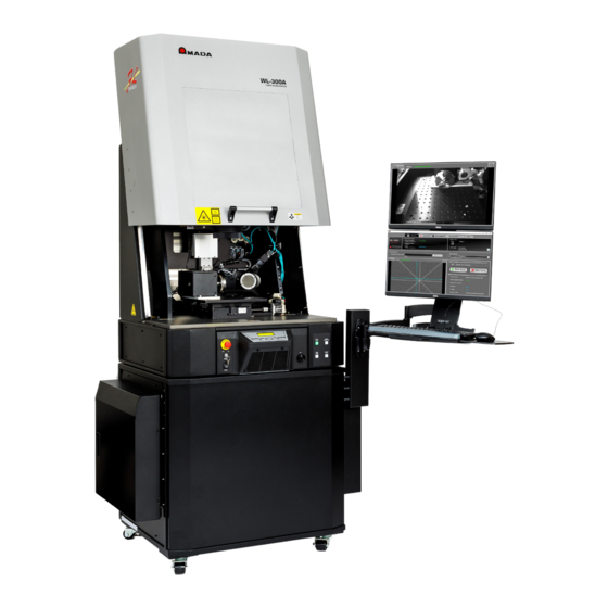
ESCRIPTION Overview Part of the WL-300 Laser Workstation series, WL-300A Galvo Laser Workstations are off-the- shelf, economical laser systems for fiber laser welding applications. They combine a pulsed or continuous wave fiber laser with galvo beam delivery and optional linear and rotary motion stages in CDRH Class I laser safety enclosures. -
Page 30: Hardware
LF Series Lasers are accommodated externally. • 200W nanosecond lasers can be accommodated in the base. Lasers currently available: 150W QCW Air-Cooled, Multi-Mode (8-521-KFD-BCA-DJA) 300W QCW Air-Cooled, Multi-Mode (8-521-KFD-BCA-DJA) 450W QCW Air-Cooled Multi-Mode (8-521-MFD-BCA-DJA) 500W CW Air-Cooled, Multi-Mode (8-521-GFB-BEA-DJA) WL-300A GALVO LASER WORKSTATION 990-949... -
Page 31: Galvo Welding Scan Head
Telecentric, Fused Silica, 163 mm (S4LFT3162/328): 70 x 70 mm field size Standard f-theta, Fused Silica, 330 mm, S4LFT1330/328: 200 x 200 mm field size Process Monitor (optional) Space to mount Monitor (MM-L300A with SU-N300A for in-line monitoring through galvo or off-axis mounting). WL-300A GALVO LASER WORKSTATION 990-949... -
Page 32: Other Features
Lead screw to prevent back-driving and maintain stage position while power is off Z-axis gantry Minimum deflection with respect to work area ¾” plate bolted aluminum gantry with multiple fasteners to workstation supports motion stages. WL-300A GALVO LASER WORKSTATION 990-949... - Page 33 1500rpm default maximum speed with 1:1 gearing ER16-mount 64mm 3-jaw chuck with 10mm thru hole ER16 manual collet up to 9.5mm (3/8” nominal) capacity Home Limit Sensor for configurations other than 1:1 WL-300A GALVO LASER WORKSTATION 990-949...
- Page 34 6.35mm travel per motor revolution LRS8-6-MONO-XY-ASSY stage Thor Labs MB3030/M tooling plate modified for stage mounting Accuracy 76µm across stage at 25C under testing conditions Repeatability 38µm across stage at 25C under testing conditions WL-300A GALVO LASER WORKSTATION 990-949...
-
Page 35: Part Number Configuration
CHAPTER 1: DESCRIPTION Part Number Configuration The WL-300A system carries a part number 8-521-XXX-XXX-XXX where each of the X characters is a configurable option. The exact laser configuration is indicated in the first six configuration characters. The last three characters are workstation specific and indicate various options. -
Page 36: Part Number Configuration Table
L = 150W Single Mode Air-Cooled QCW 150/1500 (WL-Q300A 50um core) M = 450W Single Mode Air-Cooled QCW 450/4500 (WL-Q300A 50um core) Controller F = LMC-3 Factory Automation License WL-300A format controller G = LMC-3 Factory Automation License OEM compact format controller WL-300A GALVO LASER WORKSTATION 990-949... - Page 37 F = f 120 IPG QBH D50 – F120AC (future) G = f 125 QBH Head Format A = Amada Weld Tech WL-300A (rear entry fiber) B = Amada Weld Tech OEM (top entry fiber) D = Floor standing fixed, enclosed laser engine...
- Page 38 Viewing Port A = Standard Laser Viewing Window, no off-axis CCTV B = Standard Laser Viewing Window, off-axis CCTV for part viewing C = Laser-safe opaque panel, off-axis CCTV for part viewing WL-300A GALVO LASER WORKSTATION 990-949...
-
Page 39: Options/Accessories
Feed-through on back panel for sensor Power Meter and sensor Manual swivel for rotary for Customer-installed fillet welds MM-L300A to be mounted on or off axis per customer Laser Monitor requirements. WL-300A GALVO LASER WORKSTATION 990-949... - Page 40 Light Tree or Ground Illumination Red Green Light Status Amber Blue MDS required Pneumatic valve block and Handled on MDS initially m8 sensor block for customer’s tooling integration WL-300A GALVO LASER WORKSTATION 990-949...
-
Page 41: Chapter 2: Hardware Installation
If the inside or outside of the WL-300A is stained, wipe it with a dry or slightly moistened cloth. If it is badly stained, use a neutral detergent or alcohol to clean it. Do not use paint thinner, acetone, benzene, etc. -
Page 42: Unpacking And Setup
Failure to follow these instructions completely voids safety compliance declarations and may damage your machine and/or void your warranty. The WL-300A enclosure and stand are shipped together in a single tall crate. The engine, galvo controller, and the laser optic are packaged separately. The laser engine and galvo controller will need to be installed and fastened to the stand and the laser optic must be inserted in the laser head. - Page 43 The unit is shipped with the leveling feet extended for stability in the crate. With the unit suspended on the forklift, raise the leveling feet so that the unit can be rolled when placed on the ground. Retract leveling feet WL-300A GALVO LASER WORKSTATION 990-949...
-
Page 44: Position The Enclosure
Do not lift from the front panel!! Slide the galvo controller into place, avoiding contact with the internal sides of the enclosure. The galvo controller’s front panel should be flush with the front panel of the enclosure, as shown below. WL-300A GALVO LASER WORKSTATION 990-949... - Page 45 Turn to secure. Loop and secure the cable, making sure to allow enough slack for the laser head to move up and down without bending the cable. WL-300A GALVO LASER WORKSTATION 990-949...
- Page 46 Fortunately, the boxes in the Workstation ship kit that contain the Operation Manual, QA Test Report, Dongle, etc., are the perfect size to securely prop the door open.) WL-300A GALVO LASER WORKSTATION 990-949...
- Page 47 8. Install belts Remove the bubble wrap and tape from the belt mounting. Working one side at a time, attach the belt brackets to the studs on each side. WL-300A GALVO LASER WORKSTATION 990-949...
- Page 48 All configurations of the galvo controller subassembly include connectors for integrating the controller with a laser production system. The exact configuration of the rear panel of any given workstation will vary according to the specific feature set installed. WL-300A GALVO LASER WORKSTATION 990-949...
- Page 49 The Fume Exhaust assembly is shipped with the unit but not installed. Before using, the fume exhaust assembly must installed according to the instructions in the Installation section of this document and the system checked for light leakage. WL-300A GALVO LASER WORKSTATION 990-949...
- Page 50 If the extractor tube falls out of the port it is possible that laser light can leak and void the Class 1 laser safety certification. WL-300A GALVO LASER WORKSTATION 990-949...
- Page 51 Cables should be routed into the ergo arm cable retainer channel and into the machine base where the power cables can be connected to a customer supplied power strip. The ergo arm can be mounted on the left side of the unit if desired. WL-300A GALVO LASER WORKSTATION 990-949...
- Page 52 CHAPTER 2: HARDWARE INSTALLATION WL-300A GALVO LASER WORKSTATION 990-949...
- Page 53 Under federal law, it is the responsibility of the person making modifications to a laser product to ensure that WL-300A GALVO LASER WORKSTATION 990-949...
- Page 54 CHAPTER 2: HARDWARE INSTALLATION the system is still compliant with laser safety regulations before use. Contact Amada Weld Tech or your Laser Safety Officer and review your organization’s laser safety policies if there are any questions. 19. Power Up the System Power up the system, install WinLase, insert the WinLase USB dongle from the ship kit into the PC, and connect to the fiber laser in WinLase.
- Page 55 For instructions integrating the workstation with external equipment see the Galvo Controller Operation Manual (990-945), Chapter 2, Section III.) F-Theta Lens Configuration For instructions integrating the workstation with external equipment see the Galvo Controller Operation Manual (990-945), Chapter 2, Section VI. WL-300A GALVO LASER WORKSTATION 990-949...
-
Page 56: Chapter 3: Software Installation
NSTALLATION Installing WinLase Software If your system includes a PC supplied by Amada Weld Tech, WinLase welder software has already been installed and is ready to use. If you need to install WinLase on a different PC, see Galvo Controller Operation Manual (990-945), Chapter 2, Section IV.) Installing WL300 Laser Control Software The system also ships with the WL300 Laser Control application installed. - Page 57 CHAPTER 3: SOFTWARE INSTALLATION 3. Select all prerequisites and click Next Note: If a prerequisite is already installed, a message will display 4. Agree to the terms and conditions for Microsoft Visual Studio 2013. WL-300A GALVO LASER WORKSTATION 990-949...
- Page 58 CHAPTER 3: SOFTWARE INSTALLATION 5. The Setup Successful message displays. 6. Agree to the terms and conditions for Microsoft Visual Studio 2015-2022. WL-300A GALVO LASER WORKSTATION 990-949...
- Page 59 CHAPTER 3: SOFTWARE INSTALLATION 7. The Setup Successful message displays. 8. Launch the Spinnaker Setup Wizard. Click Next 9. Accept the terms of the license agreement. WL-300A GALVO LASER WORKSTATION 990-949...
- Page 60 CHAPTER 3: SOFTWARE INSTALLATION 10. Read update notice and click Next. WL-300A GALVO LASER WORKSTATION 990-949...
- Page 61 CHAPTER 3: SOFTWARE INSTALLATION 11. Select the Camera Evaluation installation. 12. Choose the GigE Camera option. WL-300A GALVO LASER WORKSTATION 990-949...
- Page 62 CHAPTER 3: SOFTWARE INSTALLATION 13. Check installation folder and click Install. 14. Installation complete message displays. Select any of the options listed, as preferred. WL-300A GALVO LASER WORKSTATION 990-949...
- Page 63 CHAPTER 3: SOFTWARE INSTALLATION 15. Launch The WL300LaserContros Setup Wizard. Click Next. 16. Launch The WL300LaserContros Setup Wizard. Click Next. WL-300A GALVO LASER WORKSTATION 990-949...
- Page 64 CHAPTER 3: SOFTWARE INSTALLATION 17. Click Install 18. Click Finish. Installation is complete. WL-300A GALVO LASER WORKSTATION 990-949...
-
Page 65: Setting Up Ip Addresses
CHAPTER 3: SOFTWARE INSTALLATION Setting up IP Addresses The QWC laser is pre-configured with the static IP address 192.168.53.101. Accordingly, the WL-300A PC and attached devices should be configured in the IP address range 192.168.53.XXX. Use the following table to set up the IP and Subnet addresses for the devices listed. - Page 66 Blackfly cameras in the SpinView Settings tab. c. Select the first Blackfly Flir camera and click the Play button to display a continuous live image. Adjust the settings for that camera as needed. WL-300A GALVO LASER WORKSTATION 990-949...
- Page 67 Click on the configuration button to open the Device IP configuration window. Enter the address as shown below and click on “Set Current and Persistent IP Configuration.” Address Configuration IP Address 192-168-53-102 Subnet Mask 255-255-255-0 Default Gateway 192-168-53-1 WL-300A GALVO LASER WORKSTATION 990-949...
- Page 68 Check that that the IP address for the first camera ends with 102 and the address for the second camera ends with 103. Note: The camera will not be able to communicate with the PC until after the address for the PC has been configured. WL-300A GALVO LASER WORKSTATION 990-949...
- Page 69 Enter “winlase” in the Windows Search field to find and launch the WinLase LAN5 application. b. Connect to the galvo controller. c. Open the galvo controller’s Settings window, select the mode and enter the IP address as shown. WL-300A GALVO LASER WORKSTATION 990-949...
- Page 70 Note: The galvo controller will not be able to communicate with the PC until after the address for the PC has been configured. 5) Set up the PC IP address. a. Enter “View Network Connections” in the Windows search field and click on “View network connections.” A window showing current network connections displays. WL-300A GALVO LASER WORKSTATION 990-949...
- Page 71 Once the PC has booted and restarted, all of the devices (2 cameras, laser and galvo controller) should be communicating with the PC properly. If any device fails to communicate, contact Amada Weld Tech Field Support. WL-300A GALVO LASER WORKSTATION...
- Page 72 Click Update. d. The application should now be able to communicate with and control these devices. 8) Select and assign the cameras for the Main View Camera and the Off Axis Camera (if available.) WL-300A GALVO LASER WORKSTATION 990-949...
- Page 73 CHAPTER 3: SOFTWARE INSTALLATION 9) Click Update and restart the application for your changes to take effect. Click OK. WL-300A GALVO LASER WORKSTATION 990-949...
-
Page 74: Chapter 4: Operating Instructions
Before attempting to operate the system, have all personnel who will be working with the system read this manual and the Laser Safety Manual (Amada Weld Tech Part Number 990-502) thoroughly. -
Page 75: Notes
Both manuals can be found in the documentation folder on the memory stick. The reference manual is also available through the Amada Weld Tech website. It can also be accessed through the Help function in WinLase software. (Press F1 or select Help > User Guide.) -
Page 76: Workflow
If no faults have been found, the Ready light will illuminate when the laser controller has booted and obtained an IP address. Contact Amada Weld Tech support if the ready light does not illuminate after several minutes. The Shutter light will illuminate once the shutter I/O is enabled. - Page 77 Note: If one of the interlocks opens while the laser is emitting light, the laser will go into a fault state and an ILOCK fault will display. The fault must be addressed before the system can operate again. WL-300A GALVO LASER WORKSTATION 990-949...
- Page 78 The operator monitors the job in progress using the view window or the camera, which outputs to the software interface. The door opens when the job is complete. The operator manages and monitors the job through the controls and screen on the front of the unit and the software. WL-300A GALVO LASER WORKSTATION 990-949...
-
Page 79: Front Of Unit Controls
System Power: Turns the system on and off. Air Filter: The air filter is a replaceable dual element filter. Replace when dirty. Figure 4: Axis Jog Wheel and Control Buttons WL-300A GALVO LASER WORKSTATION 990-949... - Page 80 The Lighting Mode LED will be on when the lights are on. Figure 5: LCD Display and Status Indicator Lights LCD Display: Shows important information about the WL-300A system. For details of laser messages please consult the Galvo Controller Operation Manual (990-945). When equipped with the Manual Z- Jog stage, the stage motion setting (FAST/SLOW/LOCK) will be visible as well as any error messages.
-
Page 81: Software
CHAPTER 4: OPERATING INSTRUCTIONS Software The WL-300A ships with Wl-300A software which allows the user to work with the workstation via a Windows based PC. It consists of four screens. Main View The Main View screen displays the connection status of the galvo controller, the barcode reader and the laser and allows the user to logon to the system. -
Page 82: Galvo Control
Also, you can use the scroll wheel on your mouse you zoom in or out of the image. Galvo Control The Galvo Control window on the lower high right of the Main view window allows you start or stop a job cycle. It also displays the system and job status. WL-300A GALVO LASER WORKSTATION 990-949... -
Page 83: Laser Settings
These changes do not alter the settings for the selected profile permanently; they just modify them for the current task. It also displays the binary code of recent laser errors. WL-300A GALVO LASER WORKSTATION 990-949... - Page 84 Peak Power, Repeat rate and Shot Count for the selected waveform; the middle section where the user can the power percentages and times for three points in the waveform, and the upper area, which shows the shape of the pulse as it is being created. WL-300A GALVO LASER WORKSTATION 990-949...
- Page 85 Wl-Q300A workstation or Fix (QCW) or Flex (QCW) for the Wl-F300A workstation. 3. Set values for peak power, repeat rate and shot count. Click Schedule Update. Set Waveform point values In Fix mode, the user can set three points to shape the pulse.. WL-300A GALVO LASER WORKSTATION 990-949...
-
Page 86: Galvo Controller I/O
Set the time (X coordinate) and power percentage, in relation to peak power, for as many points as a required to shape the pulse. Click Schedule Update. Galvo Controller I/O The Galvo Controller I/O tab displays the active inputs and outputs for the galvo controller. WL-300A GALVO LASER WORKSTATION 990-949... -
Page 87: Job/Laser Profile
The Job/Laser Profile Tab displays the current job by part number, job name and laser profile number and lists recent jobs. It also allows the user to add a job to the list, edit or delete a listed job and save the list of jobs. WL-300A GALVO LASER WORKSTATION 990-949... -
Page 88: Setup (Network And Communication Settings)
Reader 2 IP xxxxx Reader 2 Subnet XXXXX TimeOut Interval (ms) The Camera Selection section allows the user to designate one camera as the main view camera and a second as the off axis view camera. WL-300A GALVO LASER WORKSTATION 990-949... -
Page 89: Emergency Stops
The faulty contactor or board will need to be replaced before the system can be reset. There is a faulty Reset switch or circuitry. See Chapter 5, Maintenance for details if further troubleshooting of the safety controller is required. WL-300A GALVO LASER WORKSTATION 990-949... -
Page 90: Remote Interlocks
Setting Object Properties For instructions on setting object properties, see the 4-501 Galvo Controller Operation Manual (990- 945), Chapter 3: Operating Instructions, Section III.) WL-300A GALVO LASER WORKSTATION 990-949... -
Page 91: Welding On The Fly
WinLase allows engineers to make the required job modifications, including laser power, scan speed, frequency, and timing parameters. Engineers will need to interface with the laser and scan head through EtherNet/IP and/or TCP/IP. Operators will have limited access to the programming to avoid manufacturing errors. WL-300A GALVO LASER WORKSTATION 990-949... -
Page 92: System Connections
The laser collimator is inserted through a movable light blocking tube and into the laser head inside the workstation. The standard laser interlocks prevent emission when the laser collimator is not correctly installed in the laser head. Light-tight bellows contain emitted laser light inside the enclosure. WL-300A GALVO LASER WORKSTATION 990-949... - Page 93 A wire connects the laser enclosure to the same earth potential as the laser power supply for safety. m) Fume Exhaust A 2.5” standard and 1.25” optional fume extraction port allow connection of fume extraction hoses WL-300A GALVO LASER WORKSTATION 990-949...
-
Page 94: Using The Door
Moving the door manually to one position or the other by using the handle is also acceptable. Normal operation can then be resumed. The system door range of travel can be adjusted programmatically. Contact Amada Weld Tech for details. WL-300A GALVO LASER WORKSTATION... -
Page 95: Fixturing
Z-stage travel to the range of distances over which it is possible to focus the lens. See Appendix A for details on the Z-stage travel for each configuration. WL-300A GALVO LASER WORKSTATION 990-949... -
Page 96: Task Lighting
If used with the 6” XY table option the fume extraction hose should be mounted to the table as required by the application. WL-300A GALVO LASER WORKSTATION 990-949... - Page 97 Providing the key only to qualified operators helps to control access to the unit. When the key switch is off, the door motors are disabled and the door can only be moved by hand. WL-300A GALVO LASER WORKSTATION 990-949...
- Page 98 HIGH → LOW hardware trigger, the light will re-illuminate and the process can be started again. If the Cycle Start button is not illuminated, one of the required conditions is missing; pressing the button will have no effect. WL-300A GALVO LASER WORKSTATION 990-949...
- Page 99 WinLase job or wait until the job stops running before using the Cycle Start key to reset the system. Otherwise, the hardware interlock system will detect WinLase trying to run a job with the door open condition and return to the Interlock Fault state. WL-300A GALVO LASER WORKSTATION 990-949...
- Page 100 WinLase motion objects. The Z-axis uses the upper end of travel limit switch for this purpose. Setting up the Axis Jog Control Interface When shipped from Amada Weld Tech, your laser system motion hardware is preconfigured and no motion configuration beyond installing and setting up WinLase on your own PC is required. Motion configuration files for each standard motion configuration are provided.
- Page 101 WinLase Motion Manager or by running a job. b) SYNC – the Axis Jog Control interface cannot communicate with the laser remote API. Check baud rate and API settings in WinLase as described above in step 2. WL-300A GALVO LASER WORKSTATION 990-949...
- Page 102 The direction of travel is controlled by the axis configuration in WinLase – a negative value on the Axis Jog Control Interface corresponds to the negative direction of axis travel or negative position in WinLase. WL-300A GALVO LASER WORKSTATION 990-949...
- Page 103 The Jog Interface can be locked and unlocked to prevent accidental jogging. From the main screen, press and hold the jog control to access the Main menu. Click “Lock” to select and return to the main screen. The lock symbol will display on the main screen. WL-300A GALVO LASER WORKSTATION 990-949...
- Page 104 The Axis Jog Control Interface supports Z-Axis Autofocus when equipped with an appropriate ZX-1 laser distance sensor. (For details on the –AF Adjustable Focus Head refer to Chapter 7 of the Galvo Controller Operation Manual (990-945).) WL-300A GALVO LASER WORKSTATION 990-949...
- Page 105 Select Axis is used to pick the axis jogged by the Axis Jog Control Interface. The list of axes is configured in the Configuration menu. Main Menu Unlock Perform Autofocus ↓ >> Select Axis Select Axis >> (x) R-Axis ( ) X-Axis ↓ ( ) Y-Axis WL-300A GALVO LASER WORKSTATION 990-949...
- Page 106 Select Configuration from the Main Menu to enter System Configuration sub-menu. Main Menu ↑ Change Units >> Configuration Exit Autofocus option menu Select Autofocus in the System Configuration Menu to open the Autofocus option menu. System Configuration >> Autofocus Available Axes ↓ Start-up Options WL-300A GALVO LASER WORKSTATION 990-949...
- Page 107 Physically Adjust the ZX-1 sensor so it reads zero with the laser at focus position before using the Calibrate AF option. Note: Do not use the laser distance sensor’s “Zero” function as it does not update the detected sensor value used by the Axis Jog Control Interface Autofocus feature. WL-300A GALVO LASER WORKSTATION 990-949...
- Page 108 Autofocus menu items to return “No Autofocus Sensor” if selected. Select “Save” to save the selection. Select AF Device (x) None >> ( ) ZX1-300 ↓ ( ) ZX1-100 Select AF Device ↑ ( ) ZX1-300 >> ( ) ZX1-100 Save WL-300A GALVO LASER WORKSTATION 990-949...
- Page 109 While active, pressing the Z-Axis Jog button for less than 2 seconds will toggle between FAST and SLOW. The Z-Axis stage is equipped with end of travel limit switches which will stop movement at the end of stage travel. Movement commands in the direction of the active limit will be ignored WL-300A GALVO LASER WORKSTATION 990-949...
-
Page 110: Chapter 5: Maintenance
If badly stained, use a mild detergent or alcohol to clean it. Do not use paint thinner, acetone, benzene, etc., any of which can discolor or deform the parts. WL-300A GALVO LASER WORKSTATION 990-949... -
Page 111: Section Ii: Troubleshooting
Ensure that a Shutter Fault Shutter start job signal is not being sent through External I/O or Remote API within 100ms of a shutter open event. If the trouble continues, contact Amada Weld Tech. WL-300A GALVO LASER WORKSTATION 990-949... - Page 112 The remote interlock was open when the laser Remote was firing or instructed to fire. Close the remote ILock Interlock Fault interlock, remove the partially marked part if applicable, clear the fault, and try again. WL-300A GALVO LASER WORKSTATION 990-949...
-
Page 113: Section Iii: Emergency Stop And Interlock Safety Controller Status And Error Indicators
The thinner (top) module is the Interlock Safety Module and the thicker (bottom) module is the Emergency Stop module. Figure 7 - Controller modules The procedures described below will help you to read the LED indicators and diagnose the problem. WL-300A GALVO LASER WORKSTATION 990-949... - Page 114 Error Indicators and Suggested Resolution Error Indicated Suggested Resolution Contact Malfunctions If the monitored AC contactor or safety controller contacts have welded together, you will not be able to reactivate the circuit. Replace the necessary components. WL-300A GALVO LASER WORKSTATION 990-949...
- Page 115 Fault (solid) Indicates that the safety controller plug terminator is not connected. Contact Amada Weld Tech if this error occurs. Others (off): Fault (flashing) Indicates an internal error, or that a safety controller is defective or damaged.
-
Page 116: Safety Controllers
Set the configuration dial as illustrated below. The correct configuration for automatic reset is In2- A. An incorrect configuration can cause the interlock circuit to malfunction or not provide adequate safety protection. Figure 10 - E Stop Controller - In2 Automatic WL-300A GALVO LASER WORKSTATION 990-949... -
Page 117: Laser Maintenance
If air does not clean the cover glass, then use some lens paper and a solvent to clean the cover glass (acetone, etc.) When cleaning, draw a spiral pattern from the center of the glass outward. WL-300A GALVO LASER WORKSTATION 990-949... - Page 118 CHAPTER 5: MAINTENANCE NOTE: If you cannot get the protective glass clean after several attempts, replace the protective glass with a new unit. Install the protective glass back onto the Welder head. WL-300A GALVO LASER WORKSTATION 990-949...
-
Page 119: Workstation Maintenance
The blue/white filter is installed first with the blue side facing out, then the black filter goes in second on the outside (as shown below). WL-300A GALVO LASER WORKSTATION 990-949... -
Page 120: Lubricating Door Slides
Lubrication should occur every 3-6 months, or sooner if and when symptoms of friction occur. Typical symptoms of friction include abnormal behavior like noise from the slides or difficulty opening the door. Always wipe off old grease from the tracks before reapplying. Amada Weld Tech recommends Magnalube G PTFE grease for this purpose. -
Page 121: Inspecting Bellows For Damage
The Interlock Switch Tab must be inspected for wear every six months. The rear laser bellows must be regularly inspected for damage. Safety hardware, including all safety relays, contactors, and shutter PCB, must be replaced at 10M cycles, as monitored by the user. WL-300A GALVO LASER WORKSTATION 990-949... -
Page 122: Technical Specifications
Class 1 Units conform to CDRH Class I and Class 1 under IEC60825-1. Class Laser itself is a Class 4 (IV) laser when not integrated into the WL-300A enclosure. See 4-501 Galvo Controller Operator Manual (990-945) for details on safe operation. See laser safety label on unit for data on specific configuration. -
Page 123: Environmental Specifications
(Refer to laser engine specs for laser requirements.) Power Supply: 240V~ 50/60Hz 15A Main Disconnect Fuses: Replace with 600V 15A Type CC rated ONLY SCCR: 5kA when protected by Type CC Fuses rated at 600V and 15A. WL-300A GALVO LASER WORKSTATION 990-949... -
Page 124: Laser Specification Summary
Guide Beam Max Power 1.0 mW Heat Exchange Method Air-Air Cooler Ambient Operating Temperature 41 - 95°F (5 - 35°C) Operating Humidity Less than 85% (non-condensing) Note: Nominal Values do not include measurement device error. WL-300A GALVO LASER WORKSTATION 990-949... - Page 125 * Maximum duty cycle limit is inversely proportional to peak power: 10% for 1500W, 15% for 1000W, 50% for <=300W **Maximum pulse duration limit is inversely proportional to peak power: 10ms for 1500W, 15ms for 1000W, 50ms for <=300W WL-300A GALVO LASER WORKSTATION 990-949...
-
Page 126: Laser Output Characteristics
Laser Model Full Rated Output From Fiber (W) Rated Output Power (4hrs) 300W CW 300W 300W ±3% 500W CW 500W ±3% 150/1500W QCW 150W 150W ±1% 300/3000W QCW 300W 300W ±1% 450/4500W QCW 450W 450W ±1% WL-300A GALVO LASER WORKSTATION 990-949... -
Page 127: Welding Envelope Specification
± 0.20 ± 0.20 ±0.20 ± 5.0 7.99 ± 203 ± 7.24 9.74 247.6 9.74 247.6 f330 87.24 ± 0.31 0.31 ± 8.0 ± 0.31 ± 8.0 ± 0.31 ± 8.0 ± 0.31 ± 8.0 WL-300A GALVO LASER WORKSTATION 990-949... - Page 128 ± 8.0 ± 0.31 ± 8.0 ± 0.31 ± 8.0 Processing Area Specifications by Lens - TBD WL-300A Series Lens Processing Area – 20mm SUPERSCAN IV Lens Unit f = 100mm f = 163mm f = 330mm Scanning Method Galvanometer Scanner ...
-
Page 129: Processing Field Dimensional Tolerance
LN3 Length 70 ±1.0mm 188 ±2.0mm LN4 Length 70 ±1.0mm 188 ±2.0mm 70 ±0.5mm 188 ±1.0mm LN5 Length LN6 Length 70 ±0.5mm 188 ±1.0mm LN7 Length 70 ±0.5mm 188 ±1.0mm LN8 Length 70 ±0.5mm 188 ±1.0mm WL-300A GALVO LASER WORKSTATION 990-949... - Page 130 15mm** 20mm aperture** 16.6±01 mm 80.5% 94.5% 20.7±0.1 mm 65.0% 84.5% 25.2±0.1 mm 50.8% 71.6% *These values are from Laser Mech and have proved reliable. **These are estimated using Ophir’s power through an aperture calculator. WL-300A GALVO LASER WORKSTATION 990-949...
- Page 131 APPENDIX A: TECHNICAL SPECIFICATIONS Dimensions (door closed) - Front View WL-300A GALVO LASER WORKSTATION 990-949...
- Page 132 APPENDIX A: TECHNICAL SPECIFICATIONS Dimensions Left Hand Side View WL-300A GALVO LASER WORKSTATION 990-949...
- Page 133 APPENDIX A: TECHNICAL SPECIFICATIONS Dimensions – Right Hand Side View WL-300A GALVO LASER WORKSTATION 990-949...
- Page 134 APPENDIX A: TECHNICAL SPECIFICATIONS Dimensions – Top View WL-300A GALVO LASER WORKSTATION 990-949...
-
Page 135: Tooling Plate Dimensions
APPENDIX A: TECHNICAL SPECIFICATIONS Tooling Plate Dimensions Tooling Plate (450mm x 450mm) – without XY Table option WL-300A GALVO LASER WORKSTATION 990-949... - Page 136 APPENDIX A: TECHNICAL SPECIFICATIONS Tooling Plate (300mm x 300mm) – with XY Table option WL-300A GALVO LASER WORKSTATION 990-949...
- Page 137 APPENDIX A: TECHNICAL SPECIFICATIONS AC Wiring Diagram - Wl-x300A Laser Welding Workstation WL-300A GALVO LASER WORKSTATION 990-949...
- Page 138 WL-300A GALVO LASER WORKSTATION 990-949...
- Page 139 +1-626-303-5676 FAX, +1-626-358-8048 http://www.amadaweldtech.com AMADA WELD TECH CO., LTD. 200, Ishida, Isehara-shi, Kanagawa 259-1196, Japan AMADA WELD TECH KOREA CO., LTD. 28, Dongtanhana 1-gil, Hwaseong-si, Gyeonggi-do, 18423, Korea TEL. +82-31-8015-6810 FAX. +82-31-8003-5995 AMADA WELD TECH SHANGHAI CO., LTD. Unit 401, A206(C8), No. 77, Hongcao Road, Xuhui District, Shanghai, China TEL.
- Page 140 AMADA WELD TECH INC. 1820 South Myrtle Ave., Monrovia, CA 91016, U.S.A. TEL. +1-626-303-5676 FAX. +1-626-358-8048 WL-300A GALVO LASER WORKSTATION 990-949...
Need help?
Do you have a question about the WL-300A and is the answer not in the manual?
Questions and answers