
Related Manuals for Amada ML-2450A-CE


Summary of Contents for Amada ML-2450A-CE
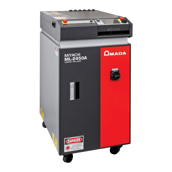
- Page 1 Original instructions YAG LASER WELDER 2450A 2451A OPERATION MANUAL OM1170632 (ML-2450A ML-2451A)-CE-E21-202308...
-
Page 2: How To Use This Document
How to Use This Document ATTENTION In this manual, ML-2450A denotes ML-2450A-CE, and ML-2451A denotes ML-2451A-CE. Thank you for purchasing our product. This operation manual explains its method of operation and precautions for use. Before using, read this operation manual carefully; after reading, save it in a proper place for your future reference. -
Page 3: Table Of Contents
Contents How to Use This Document ..........2 For Use in Safety . - Page 4 5. Connecting the Laser Controller Circuit Cable ......54 6. Connecting the External Communication Conversion Adapter (Option) ..56 Operating Part Chapter 1 Control Method, and Start and Stop .
- Page 5 Setting Data ..........159 Reading Data .
- Page 6 Timing Chart ............216 Explanation of Terminology .
-
Page 7: For Use In Safety
For Use in Safety For Use in Safety Safety Precautions Before using, read "Safety Precautions" carefully to understand the correct method of use. These precautions are shown for safe use of our products and for prevention of damage or injury to operators or others. Be sure to read each of them, since all of them are important for safety. - Page 8 For Use in Safety WARNING Wear protective glasses. Be sure to wear protective glasses having an optical density of at least 7 while using the Laser. Even if you wear them, you may lose your sight if the laser beam enters your eyes directly through protective glasses. Protective glasses attenuates the laser beam, but does not block it.
- Page 9 For Use in Safety CAUTION Do not splash water on the Laser. Water splashed over the electric parts, can cause electric shock and short circuits. Use proper tools (wire strippers, pressure wire connectors, etc.) for termination of the connecting cables. Do not cut the wire conductor.
-
Page 10: Precautions For Handling
Precautions for Handling Precautions for Handling Laser Safety Supervisor ⇒ Appoint a safety supervisor for all laser work. The appointed safety supervisor must have sufficient knowledge and experience regarding both lasers and laser work. ⇒ The supervisor must control the keyswitch of the Laser, and must be responsible for instructing operators in safety aspects of the Laser as well as directing the laser work. -
Page 11: For Transportation
Precautions for Handling For Transportation When transporting the laser, observe the following precautions to avoid hazards. ⇒ Package the Laser when transporting it. ⇒ The worker must wear a helmet, safety shoes and gloves for safety. (Leather gloves are recommended.) ⇒... - Page 12 Precautions for Handling Precautions for using a crane ⇒ When lifting the Laser, belt it between the caster and level adjuster observing a “BELT HERE” label. 注意 BELT 荷上げベルトは、左図のよ HERE うにキャスターとアジャス ターの間に通して下さい。 CAUTION BELT BETWEEN CASTERS AND ADJUSTERS AS SHOWN. Set the belt in this range.
- Page 13 Precautions for Handling Board Belt Cushion Precautions for transportation ⇒ Fix it firmly using belts, cushions, etc., to prevent a fall, damage due to vibration. ⇒ Retract the level adjuster fully when freighting the Laser. ⇒ Insert a broad and thick cushion between the front door and wall to provide enough clearance between the wall and the upper front panel of the Laser.
- Page 14 Precautions for Handling ⇒ Set the belt for fixing the laser welder within the effective range of belt setting shown in the following figure. If the belt is set from the lower part of the front side, the front door may be out of position or deformed. Avoid setting the belt in this way.
-
Page 15: For Disposal
Precautions for Handling For Disposal This product incorporates parts containing gallium arsenide (GaAs). At the time of disposal, separate it from general industrial waste or domestic waste and carry out the disposal in accordance with applicable laws and regulations. ML-2450A/2451A... -
Page 16: Sticking Warning/Danger Labels
CLEANING SOLENOID VALVE FILTER, TAKE CARE NOT TO SPLASH WATER. IF WATER ENTERS THE EQUIPMENT THROUGH VENTS, IT MAY CAUSE TROUBLE. P-00084-001 MANUFACTURED BY: AMADA WELD TECH CO.,LTD. 95-3 FUTATSUKA NODA-CITY CHIBA 278-0016 JAPAN MODEL No. SERIAL No. LABEL MFG:MONTH , YEAR... - Page 17 被ばくを回避のこと - この 開口からレーザ放射が出る。 P-00377-001 注 意 荷上げベルトは、左図のように キャスターとアジャスターの間に MANUFACTURED BY: AMADA WELD TECH CO.,LTD. CAUTION 95-3 FUTATSUKA NODA-CITY CHIBA 278-0016 JAPAN BELT BETWEEN CASTERS MODEL No. AND ADJUSTERS AS SHOWN. SERIAL No. LABEL (Also stuck on the reverse side)
- Page 18 Sticking Warning/Danger Labels 注 意 気温が0℃以下になりますと、冷却用の水が凍結し、装置が破損するおそ れがあります。特に寒冷地におきましては、凍結しやすいため、0℃以下 MATCH THE KEY TO THE GROOVE, INSERT AND TURN CLOCKWISE BY HAND TO SECURE THE FIBER OPTIC. の環境にならないようご注意ください。 DO NOT USE TOOL WHEN THE OPTICAL FIBERS CONNECT 0℃以下になる場合は、取扱説明書をご覧になり、レーザーキャビティ内、 TO LASER BEAM INPUT UNIT. 熱交換器内、ポンプ内、電磁弁内、配管内の水を完全に抜き取ってください。 ご注意...
-
Page 21: Chapter 1 Overview Of The Yag Laser Welder
1.YAG Laser Chapter 1 Introduction Part ● Overview of the YAG Laser Welder 1. YAG Laser Laser means the equipment to generate powerful light by amplifying light (electromagnetic wave) or means this light itself. Laser can be classified into various types by light generating material. -
Page 22: Mechanism Of The Yag Laser
2. Mechanism of the YAG Laser 2. Mechanism of the YAG Laser The YAG Laser for welding consists of a power supply, cooler, oscillator, optical fiber, output unit, etc. Laser light can be transferred to a place remote from the main unit by optical fiber, so that only the optical fiber and output unit can be mounted in the manufacturing line for welding. -
Page 23: Functions Of The Ml-2450A/2451A
3. Functions of the ML-2450A/2451A 3. Functions of the ML-2450A/2451A ⇒ Laser power feedback control and optional waveform control functions ■ The Laser can handle a wide variety of workpieces. Up to 32 different settings for weld schedules using waveform control are available. ■... -
Page 24: Product Composition
4. Product Composition 4. Product Composition Packaging The product is divided into the main unit and accessories and these are packed in 2 packages. The respective dimensions and mass are as follows. Mass Dimensions (including packaged products) Package for main unit Approx. - Page 25 4. Product Composition Product name Model No. Q’ty Hose band (Hose clip) HS-10 or SGT-W4/9 16-25 Water feed hand pump TP-0002 Gloves Emboss L P-00374-001 P-00474-001 P-0211 P-0212 Danger, warning, caution labels P-0213 P-00377-001 P-1213 P-1215 L-07002-001 Operation manual AS1170637(OM1170632) Power cable (5 m) A-03315-003 Main Unit, Optical Fiber, and Output Unit...
- Page 26 4. Product Composition Provided with the number of branch shutters with open-close sensor based on the number of deliveries. Model Sharing method Specification ML-245□A-010 Single delivery Output to a single fiber ML-245□A-020 2-powersharing Simultaneous output to 2 fibers ML-245□A-030 3-powersharing Simultaneous output to 3 fibers ML-245□A-040 4-powersharing...
-
Page 27: Options
4. Product Composition The output unit with the specification that you selected at the time of purchase is connected to the main unit. For details, refer to the Operation Manual or Specification for the output unit. Options The following goods are options separately sold. Purchase them as required. Part name Model No. - Page 28 4. Product Composition RS-232C/RS-485 Conversion Adapter This conversion adapter is used to control equipment by external communication. Output signals (RS-232C) of the personal computer are converted into RS-485 signals and then output to the main unit. RS-485 cable RS-485 connector of the main unit RS-232C/RS-485 conversion adapter RS-232C cable...
-
Page 29: Chapter 2 Name And Functions Of Each Section
1. Name and Function of Each Section on the Front Side Chapter 2 Introduction Part ● Name and Functions of Each Section 1. Name and Function of Each Section on the Front Side Front Cover Section This section explains each section of the front cover of the main unit. Function of Each Section on the Front Cover (1) MAIN POWER Turns ON and OFF the power supply. -
Page 30: Inside Of The Front Side
1. Name and Function of Each Section on the Front Side Inside of the Front Side The front door is opened to perform maintenance. Each section of the inside is explained below. (10) (11) EXT. I/O(3) (12) EXT. I/O(2) EXT. I/O(4) EXT. - Page 31 1. Name and Function of Each Section on the Front Side (8) REMOTE Connect it to the Remote Interlock for emergency stop. When this connector is closed, the resonator shutter and branch shutter INTERLOCK of the laser welder are closed to shut off the laser light output. Connector (9) Cooling Water Holds secondary cooling water used for cooling the YAG rod, flashlamp...
-
Page 32: Name And Function Of Each Section On The Top Side
2. Name and Function of Each Section on the Top Side 2. Name and Function of Each Section on the Top Side Top Cover Section This section explains each section of the top cover of the main unit. 1 2 3 4 5 6 (11) SHUTTER CONTROL... -
Page 33: Laser Controller (Mle-124A)
2. Name and Function of Each Section on the Top Side (8) HIGH VOLTAGE Indicates that high voltage is being supplied to the laser oscillator. Lamp (9) READY Lamp Lights up when charging of the capacitor bank has been completed. (10) MAIN SHUTTER While the resonator shutter is open, this lamp lights. -
Page 34: Laser Oscillator Section
2. Name and Function of Each Section on the Top Side (4) EMERGENCY This is an emergency stop button. With this button pressed, the laser STOP welder operation is stopped. When the pressed button is turned in the (Button) direction of RESET (clockwise), the button is reset to the initial state. This button functions in the same way as the EMERGENCY STOP button of the main unit. - Page 35 2. Name and Function of Each Section on the Top Side (3) Guide Beam Adjusts the guide beam (visible laser beam) so that this beam passes down the center of the YAG laser beam’s optical path. Reflecting Mirror (4) Power Monitor Detects the YAG laser beam and measures its power.
-
Page 36: Name And Function Of Each Section On The Lateral Side And Rear Side
3. Name and Function of Each Section on the Lateral Side and Rear Side 3. Name and Function of Each Section on the Lateral Side and Rear Side This section explains each section on the lateral side and rear side. Function of Each Section on the Lateral Side and Rear Side (1) Side Covers For both sides of the Laser. -
Page 39: Chapter 1 Installation
1. Installation Place Chapter 1 Installation and Preparation Part ● Installation This chapter explains where to install the laser welder, how to fix it, and cooling water. ⇒ At installation of this laser welder, our engineer will take charge of adjustments. Accordingly, this Operation Manual does not describe the adjusting method at a startup. -
Page 40: Environment Suitable For Installation And Precautions
1. Installation Place 500mm 500mm 500mm 500mm SHUTTER CONTROL POWER HIGH VOLTAGE READY MAIN SHUTTER 500mm Environment Suitable for Installation and Precautions ⇒ In laser processing, dust and fumes are generated from workpiece. Depending on the kind of workpiece, they may adversely affect a human body. Also, dust and fumes from workpiece may cause staining and burning of optical parts and lower the laser output. - Page 41 1. Installation Place ⇒ Avoid operating the product in the following places because a failure may occur. ■ Place where there is considerable dirt, dust, or oil mist, ■ where the Laser may be subjected to vibration or impact, ■ where the Laser may be exposed to chemicals, ■...
-
Page 42: Fixing The Laser Welder
2. Fixing the Laser Welder 2. Fixing the Laser Welder In this laser welder, fixtures are installed to protect the oscillator against vibrations and shocks during transportation. This section explains how to fix the laser welder on the floor after clearing the fixtures of the laser oscillator. Item required Phillips screwdriver, adjuster pressure fixture, and anchor, etc. - Page 43 2. Fixing the Laser Welder ⇒ For moving the laser welder after it is installed, fix the laser oscillator with the fixture to put it to the same status as when it is delivered. Fixing the Laser Welder (1) Install the attached adjusters pressure fixtures on the adjusters provided in 4 positions in the lower part of the main unit.
-
Page 44: Cooling Water
3.Cooling Water 3. Cooling Water To cool the flashlamp and YAG rod in the laser chamber of the laser oscillator, two types of cooling water are used. The primary cooling water is used to cool the secondary cooling water. Use city or industrial water for the primary cooling water. -
Page 45: Required Quantity Of Primary Cooling Water
3.Cooling Water Required Quantity of Primary Cooling Water The following graph shows the required quantity of primary cooling water at each water temperature of 25ºC, 28ºC, 30ºC and 32ºC when the using ratio is 100%. As the lamp input power ratio becomes higher, the required quantity of primary cooling water is increased more. -
Page 47: Chapter 2 Connections And Preparations Of Each Section
1. Connecting the Power Supply Chapter 2 Installation and Preparation Part ● Connections and Preparations of Each Section 1. Connecting the Power Supply CAUTION Your qualified electrician must carry out the electrical connection to main power supply. (Also follow your local accident prevention regulations, such as the German Regulation, BGVA2.) CAUTION For the power supply side, we earnestly recommend using a leakage breaker with... -
Page 48: Connecting The Hose For Primary Cooling Water
2. Connecting the Hose for Primary Cooling Water 2. Connecting the Hose for Primary Cooling Water This section explains how to connect the hose for primary cooling water to the primary cooling water inlet and the primary cooling water outlet. ⇒... -
Page 49: Preparing The Secondary Cooling Water
3. Preparing the Secondary Cooling Water 3. Preparing the Secondary Cooling Water CAUTION Use deionized water or purified water as secondary cooling water. Tap water, industrial water, ground water, or ultra pure water (16 MΩ•cm minimum resistivity) may cause corrosion or clogging, resulting in fault of the equipment. Item required Secondary cooling water (12 liters) and water feed pump Operating Procedure... -
Page 50: Connecting The Optical Fiber
4. Connecting the Optical Fiber 4. Connecting the Optical Fiber This section explains the method of connecting the optical fiber. In this laser, a high-precision type optical fiber is adopted. Once the incident optical axis is adjusted, this optical axis does not need to be adjusted again after the fiber is mounted. - Page 51 4. Connecting the Optical Fiber Standard Values of Maximum Incident Laser Energy and Power of the Optical Fiber The following table shows the standard values of maximum laser energy and power that can be input into the optical fiber. Take care not to exceed these values when using the optical fiber.
- Page 52 4. Connecting the Optical Fiber (4) Put the end of the optical fiber into the optical fiber inlet with the cap mounted. Optical fiber inlet Optical fiber To input unit To output unit Rear surface There are 2 optical fiber inlets, namely, one on the top surface and the other on rear surface of the main unit.
- Page 53 4. Connecting the Optical Fiber Connecting to Laser Beam Output Unit (1) Remove the cap at the end of the optical fiber and blow off dust by using the air blow. (2) Insert the key provided on the optical fiber plug along the groove on the output unit side.
-
Page 54: Connecting The Laser Controller Circuit Cable
5. Connecting the Laser Controller Circuit Cable 5. Connecting the Laser Controller Circuit Cable For separating the laser controller from the main unit for use, connect the circuit cable. CAUTION Be sure to turn OFF the power supply before starting a circuit cable connecting operation. - Page 55 5. Connecting the Laser Controller Circuit Cable (4) Connect the circuit cable to the laser controller and the Laser. Clamp the cable at the Laser with the cable clamp and clamp screw. Circuit cable Press and fix the cable with cable clamp ML-2450A/2451A...
-
Page 56: Connecting The External Communication Conversion Adapter (Option)
6. Connecting the External Communication Conversion Adapter (Option) 6. Connecting the External Communication Conversion Adapter (Option) To perform laser welding by external communication control (RS-485 CONTROL) by using a control unit mounting RS-232C such as personal computer, the optional conversion adapter for external communication "RS-232C/RS-485 conversion adopter"... -
Page 59: Chapter 1 Control Method, And Start And Stop
1. Control Method Chapter 1 Operating Part ● Control Method, and Start and Stop 1. Control Method This section explains the control method for the laser. The following 3 control methods are available, namely, control from the laser controller (PANEL CONTROL), control by external input/output signals connecting the PLC (*) to the laser (EXTERNAL CONTROL), and control by sending commands from the personal computer or the like (RS-485 CONTROL). -
Page 60: Start And Stop
2. Start and Stop Control by External Communication Control (RS-485 CONTROL) The control by external communication control is selected by sending a command to set the control method from the personal computer or the like connected to the main unit. ⇒... -
Page 61: Chapter 2 Various Settings
1. Setting Welding Schedules Chapter 2 Operating Part ● Various Settings 1. Setting Welding Schedules This section explains the method of setting various laser welding schedules by using the laser controller. The set schedules can be protected so that they cannot be changed. - Page 62 1. Setting Welding Schedules How to Use the Touch Panel The laser controller of this laser welder adopts a touch panel type that permits touching the screen directly for an operation. Press the displayed button portion on the screen with a finger to select a screen or perform each setting. There are screen selecting buttons, ON/OFF setting buttons, numeric value inputting buttons and others.
- Page 63 1. Setting Welding Schedules Items and Buttons Common to Each Screen The display items, setting buttons, and screen selecting buttons provided on the following screens are common to the 6 types of basic screen. Display items and setting buttons Screen selecting buttons Display items and setting buttons...
- Page 64 1. Setting Welding Schedules POSITION Sets the guide light output to ON/OFF. When the button is pressed, a window to select ON/OFF is displayed. At ON, guide light is output. At OFF, no guide light is output. The selected result (ON or OFF) is displayed at the button. The time required for guide light to go out automatically can be set by "POSITION AUTO-OFF"...
- Page 65 1. Setting Welding Schedules SCHEDULE Screen On the SCHEDULE screen, the laser light output schedules are set and registered by giving SCHEDULE numbers. If a registered SCHEDULE number is entered, the corresponding output schedules can be called. The setting items of laser output time and laser output value are different between fixed waveform (FIX) and flexible waveform (FLEX).
- Page 66 1. Setting Welding Schedules Sets the up-sloping (the laser output becomes gradually stronger) time to SLOPE "FLASH1." After setting "FLASH1", set this time in the range of SLOPE ≤ FLASH1. FLASH1 Sets the laser output time TIME [ms] and laser output value POWER [%] of the first laser in the following range.
- Page 67 1. Setting Welding Schedules SEAM Sets the fade function (*) to ON or OFF. *: Laser output value adjusting function. The laser energy is increased decreased slowly to provide a continuous waveform suitable for seam welding. When this item is set to ON, the fade function for seam welding is enabled. When the item is set to OFF, this function is disabled.
- Page 68 1. Setting Welding Schedules DEIONIZED Displays the insulation level of the secondary cooling water. WATER RES CONTROL Displays the used laser control method. EXTERNAL CONTROL (external control): DEVICE Control is exerted by the PLC connected to the EXT.I/O connector. PANEL CONTROL (internal control): Control is exerted by laser controller.
- Page 69 1. Setting Welding Schedules MONITOR Screen On the MONITOR screen, the measured value of monitored laser light is checked and the monitor value range and the upper limit value of flashlamp input power are set. How to see the displayed items : Settable item ENERGY Displays the measured value (J) of laser energy.
- Page 70 1. Setting Welding Schedules SEAM Screen On the SEAM screen, the fade-in/out function of seam welding is set. The fade- in/out function means a laser output value adjusting function. This function lowers and raises the later energy in a gentle slope form to provide a continuous waveform suitable for seam welding.
- Page 71 1. Setting Welding Schedules PASSWORD Screen On the PASSWORD screen, a password is set to protect the set welding schedule. How to see the displayed items : Settable item VALUE CHANGE Sets the validity/invalidity of the set password to ON/OFF. At OFF, the password is validated and the set values are protected.
- Page 72 1. Setting Welding Schedules PRINTOUT Screen On the PRINTOUT screen, the set values are printed by connecting an optional printer. How to see the displayed items : Settable item PRINTOUT Sets the SCHEDULE number to be printed. SCHEDULE SCHEDULE Prints the set values and waveform on the SCHEDULE screen by using the schedule number set by PRINTOUT SCHEDULE.
- Page 73 1. Setting Welding Schedules INITIALIZE Screen On the INITIALIZE screen, the equipment No. and communication conditions for using the external communication function and the alarm range of secondary cooling water temperature are set. The MEMORY SWITCH screen is displayed from the INITIALIZE screen in order to switch a special function and set the alarm range of secondary cooling water temperature.
- Page 74 1. Setting Welding Schedules MEMORY Displays the MEMORY SWITCH screen. Then, the acceptance time for laser start signal and schedule signal can be changed. SWITCH Sets brightness of the liquid crystal display to HIGH, MIDDLE or LOW. CONTRAST BUZZER Sets the sound of buzzer during the touch panel operation to ON or OFF. At ON, the buzzer sounds.
- Page 75 1. Setting Welding Schedules MEMORY SWITCH Screen When the MEMORY SWITCH button is pressed on the INITIALIZE screen, the MEMORY SWITCH screen appears. On this screen, the functions assigned to SWITCH 1 to SWITCH 6 are set. How to see the displayed items : Settable item SWITCH 1 Sets the functions assigned to 1 to 8 of "SWITCH 1"...
- Page 76 1. Setting Welding Schedules SWITCH 2 Switches the transfer speed of external communication data type assigned to 1 to 8 of "SWITCH 2" to ON or OFF. 1: Switches the data bit length. OFF: 8 bits/ ON: 7 bits 2: Sets whether a parity bit exists or not. OFF: Parity bit/ ON: No parity bit 3: Sets the parity mode.
- Page 77 1. Setting Welding Schedules SWITCH 5 Switches the functions assigned to 1 to 8 of "SWITCH 5" to ON/OFF. 1 to 5 1, 2, 3, 4, and 5: (Enabled only when the branch shutter is put under independent control) Press the setting buttons of "1" to "5" of "SWITCH 5" to set the timesharing unit numbers to be operated to ON.
-
Page 78: Setting Laser Light Output Schedules (Schedule Screen)
1. Setting Welding Schedules Setting Laser Light Output Schedules (SCHEDULE Screen) This section explains the how to set the SCHEDULE screen. On this screen, the peak value, output time, and output value of laser light are set and they are registered after SCHEDULE number are given to them. - Page 79 1. Setting Welding Schedules <Note> The settable maximum peak value of laser output differs depending on the model. ML-2450A: 7.0 kW / ML-2451A: 5.0 kW (5) Press the laser output time "TIME [ms]" and laser output value "POWER [%]" setting buttons of "FLASH1" to "FLASH3." Enter each value.
- Page 80 1. Setting Welding Schedules Setting ON/OFF for the Output Conditions for Seam Welding (1) Press the "SEAM" setting button and set the seam welding output condition to ON/OFF. At ON, the fade function for seam welding set on the SEAM screen is enabled. When this function is not used, set OFF.
- Page 81 1. Setting Welding Schedules Setting Output Schedules by Flexible Waveform (FLEX) Set the output time and output value of each POINT in the range of "POINT 01" to "POINT 20" by "FLEX" and set the laser light output that becomes a flexible waveform.
- Page 82 1. Setting Welding Schedules (7) To output laser light repeatedly, press the "SHOT" button and set the laser light output count in the range of 0000 to 9999. ⇒ When "REPEAT" is not set to 0 and "SHOT" is set to 0, laser light is continuously output until a laser stop signal is input.
-
Page 83: Setting The Output Conditions For Seam Welding (Seam Screen)
1. Setting Welding Schedules Setting the Output Conditions for Seam Welding (SEAM Screen) The method of setting the output waveform for seam welding by using the fade-in/out function after displaying the SEAM screen is explained below. The fade function increases or decreases the laser energy in a gently-sloping form to obtain a continuous waveform suitable for seam welding. - Page 84 1. Setting Welding Schedules (2) Press the "POWER [%]" setting button of "POINT 01." Enter the laser output value (%). Set the ratio to "PEAK POWER" set on the SCHEDULE screen in the range of 0 to 150.0%. (3) Likewise, set "SHOT [COUNT]" and "POWER [%]" of "POINT 02" to "POINT 06." ⇒...
- Page 85 1. Setting Welding Schedules <Note> When using the fade-in/out function, an upper/lower limit judgment of the laser energy monitor is performed only for the shot that is output by setting POWER to 100.0%. For shots other than the shot output at 100.0%, no upper/lower limit judgment is performed and both Monitor Normal and Monitor Error are not output.
-
Page 86: Setting The Output Status (Status Screen)
1. Setting Welding Schedules Setting the Output Status (STATUS Screen) In the following, the method of setting the STATUS screen is explained. On this screen, check the displayed control method and the set the branch shutter at the output destination to OPEN. Set or reset the number of laser light outputs. ⇒... - Page 87 1. Setting Welding Schedules Control by External Communication Control (RS-485 CONTROL) When a command to set a control method is sent from the personal computer connected to the main unit, external communication control is selected and "RS-485 CONTROL" is displayed in "CONTROL DEVICE" on the STATUS screen. Setting the Opening/Closing Status of the Branch Shutter To control the laser welder from the laser controller, press the "BEAM"...
- Page 88 1. Setting Welding Schedules Resetting the Number of Laser Light Outputs Reset the numeric values of "SHOT COUNT" (total number of laser light outputs) or "GOOD COUNT" (appropriate number of laser light outputs) that are displayed on the MONITOR screen. (1) Press the "RESET"...
- Page 89 1. Setting Welding Schedules When "SHOT COUNT" reaches the value set in PRESET COUNT, a screen to prompt the operator to check the flashlamp is displayed. When "GOOD COUNT" reaches the value set in PRESET COUNT, a screen to notify the number of good products is displayed.
- Page 90 1. Setting Welding Schedules Setting the Protection of Optical Fiber The optical fiber is protected from overfill to the optical fiber. When the core diameter to be used is set, the maximum possible incident light to the optical fiber is calculated to limit the lamp input power.
-
Page 91: Setting The Output Status Check Screen (Monitor Screen)
1. Setting Welding Schedules Setting the Output Status Check Screen (MONITOR Screen) In the following, the method of setting the MONITOR screen is explained. On this screen, the measured energy value of output laser light is checked, the energy range to be monitored is set, and the upper limit value of flashlamp input power is set. - Page 92 1. Setting Welding Schedules ⇒ When laser light is out of the set allowable energy range, a monitor error is output. Setting the Upper Limit Value of Lamp Input Power Set the maximum value of power to be input into the flashlamp. Since the performance of the flashlamp is gradually deteriorated, it is necessary to increase the supply power little by little.
- Page 93 1. Setting Welding Schedules When this screen appears, output pin No.9 (upper limit of lamp input) of the external output signal EXT.I/O (1) connector is open-circuited for output. Press the "TROUBLE RESET" button to clear the screen display. ⇒ After the screen display is reset, pin No.9 of the EXT.I/O (1) connector output remains in an open circuit output state.
-
Page 94: Protecting Set Values (Password Screen)
1. Setting Welding Schedules Protecting Set Values (PASSWORD Screen) The method of protecting set values by setting the password is explained below. When the password is set and validated, set values are protected and cannot be changed by any person other than the supervisor. Displaying the PASSWORD Screen (1) Press the "PASSWD"... - Page 95 1. Setting Welding Schedules When the entered password is wrong, the WRONG PASSWORD screen is displayed. Then, enter the set password once again. Validating the Password (1) Press the "VALUE CHANGE" setting button. A window to select ON/OFF is opened. At ON, the set password can be changed.
- Page 96 1. Setting Welding Schedules Setting a New Password (1) Enter a new password into the password input box. Enter 4 alphanumerical characters. (2) Press the ENTER key on the keyboard. A confirmation screen appears. (3) Enter the same password and press the ENTER key. The set password is registered and the PASSWORD screen reappears.
- Page 97 1. Setting Welding Schedules The items that can be protected are as follows. Display Screen Item SCHEDULE Screen SCHEDULE (Schedule number) FORM (FIX/FLEX waveform switching) PEAK POWER (Laser output peak value) SEAM (Fade function ON/OFF) REPEAT (Number of laser light outputs per second) SHOT (Total number of laser light outputs) SLOPE (Time for up-sloping to FLASH1) ...
-
Page 98: Switching The Accuracy Of The Measured Laser Energy Value (J) (Memory Switch Screen)
1. Setting Welding Schedules Switching the Accuracy of the Measured Laser Energy Value (J) (MEMORY SWITCH Screen) In the following, the method of switching the measurement accuracy of the laser energy value (J) by displaying the MEMORY SWITCH screen from the INITIALIZE screen is explained. - Page 99 1. Setting Welding Schedules (3) Press the MEMORY SWITCH button. The MEMORY SWITCH screen appears. Switching the Accuracy of the Measured Value (J) (1) Move the cursor to "6" of "SWITCH 1" and press the ON key. <Note> When the accuracy of the measured value is switched, the set values of SCHEDULE are initialized.
- Page 100 1. Setting Welding Schedules Setting example after switching ("6" of SWITCH 1: ON) <No te> When No.6 of SWITCH 1 is set to ON, the settable maximum peak value of laser output "PEAK POWER" on the SCHEDULE screen becomes 1.0 kW regardless of the model.
-
Page 101: Switching The Pulse Width Setting Range (Memory Switch Screen)
1. Setting Welding Schedules Switching the Pulse Width Setting Range (MEMORY SWITCH Screen) In the following, the method of changing the pulse width setting range for laser light (laser output time ms) by displaying the MEMORY SWITCH screen from the INITIALIZE screen is explained. Usually, this setting permits switching the pulse width of 0.1 ms step over to 0.05 ms step, so that more minute welding work can be performed. - Page 102 1. Setting Welding Schedules (3) Press the MEMORY SWITCH button. The MEMORY SWITCH screen appears. Switching the Pulse Width Setting Range (1) Move the cursor to "7" of "SWITCH 1" and press the ON key. <No te> When the pulse width setting range is switched, the set values of SCHEDULE are initialized.
- Page 103 1. Setting Welding Schedules Setting example after switching ("7" of SWITCH 1: ON) ⇒ On the FLEX screen, the screen is switched and displayed in the same way. <Note> The value of "FLASH1"+ "COOL1" + "FLASH2"+ "COOL2" + "FLASH3" is as follows after the setting of "7"...
-
Page 104: Setting The Laser Light Delivery
2. Setting the Laser Light Delivery 2. Setting the Laser Light Delivery This laser can output single laser light to multiple optical fibers or to a single optical fiber by the functions of the built-in beamsplitter and timesharing unit. This section explains the sharing specifications of this laser. Laser Light Sharing The laser light sharing specification is divided into powersharing and timesharing. - Page 105 2. Setting the Laser Light Delivery Laser light can also be output by a sharing method other than the above so that the timesharing unit may not be operated even when the branch shutter is opened. For this setting, set the independent control of the branch shutter by using the DIP switch in the main unit and then set the branch shutter and timesharing unit to be operated on the MEMORY SWITCH screen.
- Page 106 2. Setting the Laser Light Delivery 2-timesharing delivery to 6-timesharing delivery One optionally selected out of the built-in branch shutters is opened to output laser light. For example, when branch shutter 2 is opened, laser light is output to the optical fiber connected to input unit 2.
- Page 107 2. Setting the Laser Light Delivery 6-timesharing Timesharing Timesharing Timesharing Timesharing Timesharing Beamsplitter unit unit unit unit unit 100% 100% 100% 100% 100% 100% Laser light Branch shutter 6 Branch shutter 5 Branch shutter 4 Branch shutter 3 Branch shutter 2 Branch shutter 1 Laser light is reflected on the beamsplitter by operated timesharing unit and transferred from opened branch shutter 1 to 6.
-
Page 108: Operating Branch Shutters On The Status Screen
2. Setting the Laser Light Delivery 2 timesharings of 3-powersharing deliveries Timesharing Beamsplitter Beamsplitter Beamsplitter unit 100% 100% Laser light Beamsplitter Beamsplitter Beamsplitter 100% Branch shutter 6 Branch shutter 5 Branch shutter 4 Branch shutter 3 Branch shutter 2 Branch shutter 1 Laser light is reflected and branched on the front or rear beamsplitter by the operation of the timesharing unit. - Page 109 2. Setting the Laser Light Delivery Operating Procedure (1) Press the "BEAM" button. A window to set the opening/closing of the branch shutter is opened. (2) Press the setting button for "SHUTTER 1" to "SHUTTER 6" corresponding to the connected optical fiber to set it to ON. "SHUTTER 1"...
-
Page 110: Controlling Branch Shutters Independently
2. Setting the Laser Light Delivery Controlling Branch Shutters Independently In the following, the method of setting branch shutters to independent control by setting DIP switches. ⇒ Usually, the sharing specification is changed by our engineer. When "SHUTTER 1" to "SHUTTER 6" are set to ON and the branch shutter is opened, the branch shutter and the timesharing unit are automatically operated to transmit laser light. - Page 111 2. Setting the Laser Light Delivery Operating an Optional Branch Shutter and Timesharing Unit (1) After putting the branch shutter under independent control, press the MEMORY SWITCH button on the INITIALIZE screen. The MEMORY SWITCH screen is displayed. (2) Press the setting buttons of "1" to "6" of "SWITCH 4" to set the branch shutter No.
- Page 112 2. Setting the Laser Light Delivery Timesharing Beamsplitter Beamsplitter unit 100% 100% Laser light Branch shutter 3 Branch shutter 2 Branch shutter 1 100% Single 2-powersharing In the case of 2-powersharing delivery + single delivery, laser light is output from branch shutters 1 and 2 as 2-powersharing delivery and from branch shutter 3 as single delivery, depending on a difference in beamsplitter mounting condition.
-
Page 113: Changing The Acceptance Time For Laser Start Signal/Schedule Signal (Memory Switch Screen)
3. Changing the Acceptance Time for Laser Start Signal/Schedule Signal 3. Changing the Acceptance Time for Laser Start Signal/ Schedule Signal (MEMORY SWITCH Screen) This section explains how to change the acceptance time for the laser start signal and schedule signal to be input into the EXT.I/O (1) connector by setting the DIP switches provided in the side face of the main unit when EXTERNAL CONTROL is exerted by external input/output signals. - Page 114 3. Changing the Acceptance Time for Laser Start Signal/Schedule Signal Displaying the MEMORY SWITCH Screen (1) Turn OFF the CONTROL keyswitch and turn ON the MAIN POWER switch. Power is supplied and the POWER lamp comes on. The screen of model name appears.
- Page 115 3. Changing the Acceptance Time for Laser Start Signal/Schedule Signal Changing the Acceptance Time (1) Press the setting buttons of "2", "3", and "4" of "SWITCH 3" to set them to ON. For example, to set the acceptance time to 4 ms, set "2" to OFF, "3" to "ON, and "4"...
-
Page 116: Setting The Function Of The Output Unit With Fiber Sensor (Option)
4. Setting the Function of the Output Unit with Fiber Sensor (Option) 4. Setting the Function of the Output Unit with Fiber Sensor (Option) For using the output unit with fiber sensor (option), perform a setting to make the function effective by the DIP switches provided in the side face of the main unit. This section explains how to set the function of the output unit with fiber sensor. - Page 117 4. Setting the Function of the Output Unit with Fiber Sensor (Option) Operating Procedure (1) Set the fiber breakage detecting function. Remove the side cover of the main unit and set No.3 of SW1 to ON. The fiber breakage detecting function is set. When optical fiber breakage or end face damage is detected during laser light output, Error No.38 to 43 FIBER SENSOR 1 to 6 TROUBLE is displayed.
-
Page 119: Chapter 3 Laser Welding By Laser Controller (Panel Control)
1. Operation Flow Chapter 3 Operating Part ● Laser Welding by Laser Controller (PANEL CONTROL) 1. Operation Flow This section explains a laser welding operation flow by laser controller. The following methods for laser welding operations are available: control from the laser controller (PANEL CONTROL), control by external input/output signals from the connected PLC (Programmable Logic Controller) (EXTERNAL CONTROL), and control by sending a command from the connected personal computer (RS-485... -
Page 120: Laser Controller Functions
2. Laser Controller Functions 2. Laser Controller Functions This section explains the functions of the laser controller. At PANEL CONTROL, welding schedules are set by using the liquid crystal display of the laser controller and laser light is output by pressing the LASER START/STOP button. -
Page 121: Operating Procedure
3. Operating Procedure 3. Operating Procedure This section explains the operating procedure for laser welding to be controlled from the laser controller. ⇒ For the details of welding schedule settings, refer to Chapter 2, "1. Setting Welding Schedules" on page 59. For connector functions, refer to Chapter 4, "3. Connector Functions"... - Page 122 3. Operating Procedure (2) Turn ON the CONTROL keyswitch. The laser is put to an operable status and the COOLER → ON !! screen appears. How to see the displayed items PUMP Displays the ON/OFF status of the pump to circulate cooling water. WATER TEMP Indicates the secondary cooling water temperature.
- Page 123 3. Operating Procedure After completion of charging, the READY !! screen appears for 0.5 sec. After the READY !! screen appears, the screen (SCHEDULE screen, STATUS screen, or MONITOR screen) displayed at the previous completion appears. Setting Output Schedules As an example, the procedure for setting SCHEDULE No.05, laser output peak value 5.00 kW, FLASH1 laser output time 3.6 ms/output value 60%, and up-slope 0.6 ms is explained below.
- Page 124 3. Operating Procedure <No te> The settable maximum peak value of laser output differs depending on the model. For the laser output value setting (% of FLASH), set a value not exceeding the maximum value of each model. ML-2450A: 7.0 kW ML-2451A: 5.0 kW (4) Press the "TIME [ms]"...
- Page 125 3. Operating Procedure ⇒ For the laser output value, set the ratio (%) supposing that the set laser output peak value is 100%. In this example, this peak value is 60% of "PEAK POWER=5.00 kW", so that the actual laser output value is 3.0 kW. In this case, even if "PEAK POWER=3.00 kW"...
- Page 126 3. Operating Procedure (2) Adjust the workpiece and output unit positions to set an appropriate work distance (distance between the workpiece and the output position). (3) Press the "MAIN SHUT" setting button to set it to ON to open the resonator shutter.
- Page 127 3. Operating Procedure (9) Press the LASER START/STOP button. Laser light is output. ⇒ Before pressing the LASER START/STOP button, display the SCHEDULE screen or MONITOR screen and input another registered SCHEDULE number. With this, laser light is output in the output conditions of this SCHEDULE. (10) Press the "MON"...
-
Page 129: Chapter 4 Laser Welding By External Input/ Output Signals (External Control)
1. Operation Flow Chapter 4 Operating Part ● Laser Welding by External Input/ Output Signals (EXTERNAL CONTROL) 1. Operation Flow This section explains an operation flow of laser welding by external input/ output signals (EXTERNAL CONTROL). The following methods for laser welding operations are available: control from the laser controller (PANEL CONTROL), control by external input/output signals from the PLC (Programmable Logic Controller) connected to the connector (EXTERNAL CONTROL), and control by sending a command from the connected personal... -
Page 130: Preparations For Operations
2. Preparations for Operations 2. Preparations for Operations This section explains the devices and connectors required for laser welding by external input/output signals (EXTERNAL CONTROL). Connect the PLC to the EXT.I/O (1), (2), (3) or (4) connectors provided in the front of the main unit to control the main unit by executing the program from the outside. -
Page 131: Connector Functions
3. Connector Functions 3. Connector Functions Pin Arrangement and Functions There are 4 connectors to be connected for the control by external input/output. This section explains the arrangement and functions of the respective pins. EXT.I/O (1) Connector (D-Sub 37 pin) The EXT.I/O (1) connector inputs welding schedules and inputs or outputs the start signal of guide light and laser light. - Page 132 3. Connector Functions Input Pins of EXT.I/O (1) Connector ⇒ Supply power to pin No.16 and pin No.17 and put the section between pin No.23 and COM in a closed circuit. Pin No. Description 0 V OUT Power supply for external input signals. This pin is exclusively used for the ML- 2450A/2451A.
- Page 133 3. Connector Functions Pin No. Description BEAM SELECT 3 When this Pin 27–COM circuit is closed, laser beam input unit 3 is selected and the unit becomes ready to project a laser beam. BEAM SELECT 4 When this Pin 28–COM circuit is closed, laser beam input unit 4 is selected and the unit becomes ready to project a laser beam.
- Page 134 3. Connector Functions Output Pins of EXT.I/O (1) Connector Pin No. Description Ready When the high voltage is turned ON and the capacitor is fully charged, this Pin 1–COM circuit is closed internally. High Voltage ON While the high voltage is supplied, this Pin 2–COM circuit is closed internally. Trouble If trouble arises, this Pin 3–COM circuit is opened internally until it is reset.
- Page 135 3. Connector Functions EXT.I/O (2) Connector (D-Sub 25 pin) The EXT.I/O (2) connector inputs and outputs control signals for the timesharing unit and branch shutter. ⇒ Use the following product out of the attached connectors. Plug Case Manufacturer HDBB-25P(05) HDB-CTH(10) HIROSE ELECTRIC CO., LTD.
- Page 136 3. Connector Functions Pin No. Description Timesharing unit 5 (Enabled only when the branch shutter is put under independent control) When the section between this pin and COM is put in a closed circuit, timesharing unit 5 is operated so that laser light can be output from input unit 5. Unused Do not connect anything.
- Page 137 3. Connector Functions EXT.I/O (3) Connector (D-Sub 9 pin) The EXT.I/O (3) connector inputs and outputs an emergency stop signal for the laser. ⇒ Use the following product out of the attached connectors. Plug Case Manufacturer HDEB-9P(05) HDE-CTH(10) HIROSE ELECTRIC CO., LTD. Emergency stop output (out) (out) Emergency stop output Emergency stop input (in)
- Page 138 3. Connector Functions EXT.I/O (4) Connector (D-Sub 25 pin) The EXT.I/O (4) connector inputs and outputs an emergency stop signal for the laser and inputs an external interlock signal. ⇒ Use the following product out of the attached connectors. Socket Case Manufacturer HDBB-25S(05)
- Page 139 3. Connector Functions Output Pins of EXT.I/O (4) Connector Pin No. Description Emergency stop output 1 When the laser is put in an emergency stop, the section between pin No.9 and pin No.12 is put in an open circuit. Emergency stop output 2 When the laser is put in an emergency stop, the section between pin No.10 and pin No.11 is put in an open circuit.
- Page 140 3. Connector Functions EXT.I/O (4) Connector Inside the laser User ESTOP Wiring ESTOP CH2 rtn ESTOP CH 1 rtn ESTOP CH 2 ESTOP CH 1 ESTOP Out 1a ESTOP Out 1b ESTOP Out 2a ESTOP Out 2b Interlock rtn 2 Interlock out 2 User Interlock Wiring (dry contact closure)
- Page 141 3. Connector Functions In this wiring example a Pilz PNOZ family safety relay module controls the Laser and interfaces two external emergency stop buttons. In this example the Pilz device would also control additional emergency stop functions outside of the Laser using expansion contacts.
- Page 142 3. Connector Functions REMOTE INTERLOCK Connector The REMOTE INTERLOCK connector closes the branch shutter and connects the interlock to cut off laser light in an emergency. ⇒ Use the following product out of the attached connectors. Plug Case Manufacturer 116-12A10-2AF10.5 TAJIMI ELECTRONICS CO., LTD.
-
Page 143: Example Connections Of External Input Signals
3. Connector Functions Example Connections of External Input Signals An example of external input signal connections of the EXT.I/O connector is explained below. When External Inputs are Contacts Inside of the laser EXT.I/O (1) Connector D-Sub 37 pin 24V DC +24 V 100 mA max. - Page 144 3. Connector Functions When External Inputs are NPN Transistors 24V DC 0V OUT +24V OUT External signal source External signal COM Input COM When External Inputs are PNP Transistors 24V DC 0V OUT +24V OUT External signal source External signal COM Input COM When External Power Source is Supplied 24V DC...
-
Page 145: Example Connection Of External Output Signals
3. Connector Functions Example Connection of External Output Signals An example of external output signal connections of the EXT.I/O connector is explained below. Inside of the laser EXT.I/O (1) Connector D-Sub 37 pin READY High voltage on [HV-ON] TROUBLE Monitor normal [NORMAL] Monitor trouble [LOW/HIGH] External input receivable Lamp power upper limit [CHECK THE LAMP]... -
Page 146: Programming
4. Programming 4. Programming This section explains the precautions for programming laser welding by external input/output signals (EXTERNAL CONTROL). The timing chart of the appendix shows the input signal length and input waiting time required to correctly operate the laser. Perform actual programming referring to this timing chart. - Page 147 4. Programming Opening the Resonator Shutter (1) Close pin No.24 of the EXT.I/O (1) connector. The resonator shutter is opened and the flashlamp comes on. Then, a laser light output is enabled. Setting Output Schedules (SCH.#01) Control switching input (1) Set the SCHEDULE number by combining pin No.29 to pin No.33 of the EXT.I/O (1) connector.
- Page 148 input SCHEDULE 1 input 16.0ms or more 4. Programming SCHEDULE 2 input ↓ ↓ ↓ Over the time set on the MEMORY SWITCH screen Control switching 150ms or more input Laser start input The time set on the MEMORY SWITCH screen External input Output...
- Page 149 SCHEDULE 1 input 4. Programming 16.0ms or more SCHEDULE 2 ↓ input Over the time set on the MEMORY SWITCH screen Laser start input The time set on the MEMORY SWITCH screen Output (Laser light) 40ms End output Monitor normal/ trouble output Stopping the Operation (1) Put the section between pin No.18 of the EXT.I/O (1) connector and COM in an...
-
Page 151: Chapter 5 Laser Welding By External Communication Control (Rs-485 Control)
1. Operation Flow Chapter 5 Operating Part ● Laser Welding by External Communication Control (RS-485 CONTROL) 1. Operation Flow This section explains an operation flow of a laser welding by external communication control (RS-485 CONTROL). The following methods for laser welding operations are available: control from the laser controller (PANEL CONTROL), control by external input/output signals from the PLC (Programmable Logic Controller) connected to the connector (EXTERNAL CONTROL), and control by sending a command from the connected personal... -
Page 152: Preparations For Operations
2. Preparations for Operations 2. Preparations for Operations Up to 16 laser units can be controlled from a single personal computer. The equipment configuration and connector connections are shown in the following figure. Personal computer, etc. Equipment No.00 Equipment No.01 Equipment No.15 RS-485 RS-232C... -
Page 153: Initial Settings
3. Initial Settings 3. Initial Settings Perform initial settings to control laser welding by external communication (RS- 485 CONTROL). Set communication schedules and equipment No. on the laser controller of the laser. The communication schedules for data transfer are as follows. Data transfer system Conforming to RS-485, asynchronous, full duplex Transfer rate... - Page 154 3. Initial Settings (2) While the model name screen is displayed (for about 3 seconds), press the corners of the touch panel display in the order shown in the figure above. The INITIALIZE screen appears. ⇒ Unless the CONTROL keyswitch is OFF, the INITIALIZE screen does not appear. (3) Press the "MEMORY SWITCH"...
-
Page 155: Setting Equipment No
3. Initial Settings Specifying Communication Schedules (1) Set communication schedules by setting 1 to 6 of "SWITCH 2" to ON or OFF. Move the cursor to the switch to be changed and press the ON key or OFF key for this setting. 1: Data bit length (OFF: 8 bits, ON: 7 bits) 2: Parity bit... - Page 156 3. Initial Settings Displaying the INITIALIZE Screen (1) Turn OFF the CONTROL keyswitch and turn ON the MAIN POWER switch. Power is supplied and the POWER lamp comes on. The screen of model name appears. ① ③ ④ ② (2) While the model name screen is displayed (for about 3 seconds), press the corners of the touch panel display in the order shown in the figure above.
-
Page 157: Commands
4. Commands 4. Commands This section explains the commands that are used to control laser welding by external communication. Code Table The codes for external communication with a personal computer and the text structure are as follows. For details, refer to "Setting Data" on page 155 to "Reading Error No. - Page 158 4. Commands Code Contents Text structure PC to laser Laser stop command External communication Laser to PC control is not performed. PC to laser Trouble reset command External communication Laser to PC control is not performed. PC to laser SHOT COUNT reset command External communication...
-
Page 159: Setting Data
4. Commands Setting Data The command (code: W) to set welding schedules by specifying equipment No. and schedule No. is explained below. CH1/CH0 Equipment No. (CH1 = tens digit, CH0 = units digit) Classification No. of the setting (LA1 = tens digit, LA0 = units digit) 99 Settings for the cooler (Set the schedule No. -
Page 160: Reading Data
4. Commands Reading Data The command (code: R) to read the set values and monitor values of welding schedules by specifying equipment No. and schedule No. is explained below. CH1/CH0 Equipment No. (CH1 = tens digit, CH0 = units digit) Classification No. -
Page 161: Schedule Settings For Both Fix And Flex
4. Commands Set Value/Monitor Value Table ⇒ The items marked * are monitor values. These values can be read out but cannot be set. ⇒ The value in ( ) indicates the unit. ⇒ The unit of time setting depends on the setting of "7" of SWITCH 1 on the MEMORY SWITCH screen. -
Page 162: Schedule Settings For Flex, Time 01 To
4. Commands Data No. Item Data Range [FLASH 1] TIME on the [SCHEDULE] screen 000 – 999 (×0.1ms/x0.01ms) [FLASH 2] TIME on the [SCHEDULE] screen 000 – 999 (×0.1ms/x0.01ms) [FLASH 3] TIME on the [SCHEDULE] screen 000 – 999 (×0.1ms/x0.01ms) SLOPE] TIME on the [SCHEDULE] screen 000 –... -
Page 163: Schedule Settings For Flex, Power 01 To
4. Commands Data No. Item Data Range [POINT 20] TIME on the [SCHEDULE] screen 000 – 999 (×0.1ms/x0.01ms) [REFERENCE VALUE] on the [SCHEDULE] screen 0000 – 9999 (×0.1J) Approximate laser output energy of the set waveform 88 Schedule Settings for FLEX ― POWER 01 to 10 Data No. -
Page 164: Seam Setting Value Shot 01 To
4. Commands 76 SEAM setting value SHOT 01 to 10 Data No. Item Data Range [POINT 01] SHOT on the [SEAM] screen 0000 − 9999 [POINT 02] SHOT on the [SEAM] screen 0000 − 9999 [POINT 03] SHOT on the [SEAM] screen 0000 −... -
Page 165: Seam Setting Value Power 11 To
4. Commands 79 SEAM setting value POWER 11 to 20 Data No. Item Data Range [POINT 11] POWER on the [SEAM] screen 0000 − 1500 (×0.1%) [POINT 12] POWER on the [SEAM] screen 0000 − 1500 (×0.1%) [POINT 13] POWER on the [SEAM] screen 0000 −... - Page 166 4. Commands ⇒ If the pulse width becomes long, the total number of waveform data can be controlled to 108 or less by extending the measurement interval. (Example) * When the pulse width is 00.5 to 05.0 ms, a measured value is sent at intervals of 0.05 ms.
-
Page 167: Setting The Control Method, Schedule No., Branch Shutter, Etc
4. Commands Setting the Control Method, SCHEDULE No., Branch Shutter, etc. The command (code: WS) to set the control method, SCHEDULE No., branch shutter, high voltage ON/OFF status, guide light ON/OFF status, automatic laser power value transmission ON/OFF status, etc. by specifying equipment No. is explained below. -
Page 168: Setting The Mirror Of The Timesharing Unit
4. Commands * When the external input/output control is turned OFF at "5: Control by external input/output signals (Output schedules are set on the personal computer)", the control method is changed to "2: Control by external communication control." HV (high voltage) (0: OFF 1: ON □: Current status kept) LD (guide light) (0: OFF 1: ON □: Current status kept) Resonator shutter (0: OFF 1: ON □: Current status kept) Branch shutter 1 (0: OFF 1: ON □: Current status kept) -
Page 169: Reading The Control Method, Schedule No., Branch Shutter, Etc
4. Commands ML-2450A Timesharing unit 4 (0: OFF 1: ON □: Current status kept) ML-2451A Unused (fixed to □) ML-2450A Timesharing unit 5 (0: OFF 1: ON □: Current status kept) ML-2451A Unused (fixed to □) Valid only at external communication control. If there is any setting that ACK or NAK cannot be changed, all are invalidated and [NAK] is returned. -
Page 170: Reading The Timesharing Unit Status
4. Commands Automatic laser power monitor value transmission (0: OFF 1: ON) Each time the flashlamp comes on, "00 Laser Power Monitor-Energy, number of waveform data, etc." on page 165 is sent. READY status (0: Laser start disabled 1: Laser start enabled) Reading the Timesharing Unit Status The command (code: RM) to read the timesharing unit status is explained below. -
Page 171: Stopping A Laser Light Output
4. Commands CH1/CH0 Equipment No. (CH1 = tens digit, CH0 = units digit) If the Laser is ready for use, it returns an [ACK]. If not, the Laser returns a [NAK]. The Laser is not ready for use when: ACK or NAK •... -
Page 172: Resetting The Total Number Of Outputs
4. Commands Resetting the Total Number of Outputs The command (code: C1) to reset the total number of outputs (SHOT COUNT) is explained below. CH1/CH0 Equipment No. (CH1 = tens digit, CH0 = units digit) The Laser accepts the command only when in external communication ACK or NAK control (RS-485 CONTROL) mode. - Page 173 4. Commands Error No. (E1 = tens digit, E0 = units digit) All error numbers are transmitted. If no error has occurred, the error No. is to E1/E0 be [00]. For the contents corresponding to error No., refer to "Table of Error Contents"...
-
Page 175: Chapter 6 Printing Set Values And Measured Values
1. Printing Set Values Chapter 6 Operating Part ● Printing Set Values and Measured Values When the Printer Model BL2-58SNWJC (option) manufactured by SANEI ELECTRIC INC. is connected to the laser by using an RS-485 cable, the output schedules of each SCHEDULE and the measured values of the MONITOR screen can be printed. - Page 176 1. Printing Set Values Executing Printing (1) Press the "SCHEDULE" button. The output schedules of the specified SCHEDULE are printed. Example Example FORM:FIX (fixed waveform setting) FORM:FLEX (flexible waveform setting) ML-2450A/2451A...
-
Page 177: Printing Measured Values
2. Printing Measured Value 2. Printing Measured Values ⇒ If the power supply is OFF, turn ON the MAIN POWER switch and then turn ON the CONTROL keyswitch. ⇒ To print measured values, set welding schedules and output laser light actually. After making sure that the measured waveform is displayed, perform the following operations. -
Page 178: Printing Set Values For Seam Welding
3. Printing Set Values for Seam Welding 3. Printing Set Values for Seam Welding ⇒ If the power supply is OFF, turn ON the MAIN POWER switch and then turn ON the CONTROL keyswitch. When one of the SCHEDULE screen, STATUS screen, and MONITOR screen is displayed on the laser controller, perform the following operations. -
Page 181: Chapter 1 How To Perform Maintenance
1. Maintenance Parts and Standard Intervals of Inspection/Replacement Chapter 1 Maintenance Part ● How to Perform Maintenance NOTE Before starting maintenance, read the following items and take extreme care. WARNING ■ Before starting maintenance operations, be sure to turn OFF the power supply. If a high voltage is already applied, turn OFF the power supply and then start these operations at least in 5 minutes. - Page 182 1. Maintenance Parts and Standard Intervals of Inspection/Replacement Operation Contents of Part name Model No. interval operation (standard) (*1) (*2) Cartridge (Ion-exchanger) MLF-0025-00 3 years Replace (With one bag of ion-exchange resin) Water filter CW-5PM-H 6 months Replace Floating panel Z-00869-001 1 year Replace...
- Page 183 1. Maintenance Parts and Standard Intervals of Inspection/Replacement usable period ends. *3: The number of flashes as an indication of the life of the lamp (lowering of light quantity, cracks in the lamp, and a lighting failure) differs greatly depending on the laser output conditions and the laser irradiation interval. When the flashlamp is used in a single shot or with a long standby time as compared with continuous flash in repetition of several shots to several tens of shots per second, the number of flashes may become...
-
Page 184: Maintenance Of The Cooler Unit Section
2. Maintenance of the Cooler Unit Section 2. Maintenance of the Cooler Unit Section This section explains the maintenance of the coolant unit, including cleaning of the solenoid valve filter, water drain of the primary cooling water and secondary cooling water tanks, maintenance of the ion-exchanger, and water drain for the case where the laser welder is not used for a long time. - Page 185 2. Maintenance of the Cooler Unit Section (4) The staffing assembly and the valve body are temporarily assembled. Remove the valve body by pulling them. ⇒ Take care not to lose the main valve screw. Body mounting screw (4 pieces) The keys of the staffing assembly are hooked to the valve body (4 positions).
-
Page 186: Draining Water From The Primary Cooling Water
2. Maintenance of the Cooler Unit Section Draining Water from the Primary Cooling Water When the laser welder must be moved or transferred or its operation is stopped over one month, drain the primary cooling water. ⇒ For changing the ion-exchange resin for repacking, changing the ion-exchanger, changing the water filter, and changing the secondary cooling water, the primary cooling water does not need to be drained. -
Page 187: Draining Water From The Secondary Cooling Water Tank
2. Maintenance of the Cooler Unit Section Draining Water from the Secondary Cooling Water Tank For changing the ion-exchange resin for repacking, changing the ion-exchanger, and changing the secondary cooling water (once every 6 months), drain water from the cooling water tank to make the tank empty. For moving or transporting the laser welder and stopping it over one month, make the cooling water tank empty. -
Page 188: Changing The Ion-Exchange Resin And Replacing The Ion-Exchanger
2. Maintenance of the Cooler Unit Section Changing the Ion-Exchange Resin and Replacing the Ion-Exchanger The ion-exchange resin in the ion-exchanger has a function to keep high purity by removing the ion generated by deteriorated secondary cooling water. Change the ion-exchange resin with a new one within 6 months after use. - Page 189 2. Maintenance of the Cooler Unit Section (4) Remove the cap of the ion-exchanger and discard the used ion-exchange resin. Cross-recessed head machine screw with washer (M4, 16mm in length, material SUS) Remove the 4 cross- recessed head machine Discard the used ion- screws with washer and exchange resin.
- Page 190 2. Maintenance of the Cooler Unit Section Installing the Ion-Exchanger (1) Insert the ion-exchanger and turn it clockwise with the mounting/removing tool. <No te> Use the mounting/removing tool for installing the ion-exchanger. If the mounting/ removing tool is too tightened, the thread portion may be broken. (2) Put cooling water up to the line under HIGH of the water level label with the attached water feed pump.
-
Page 191: Changing The Water Filter And Secondary Cooling Water
2. Maintenance of the Cooler Unit Section Changing the Water Filter and Secondary Cooling Water The water filter has a function to filter the secondary cooling water to keep its purity. Change the water filter and the secondary cooling water every 6 months. ⇒... -
Page 192: Water Drain When The Laser Welder Is Not Used Over One Month Or The Room Temperature At The Installation Place Goes Down Below 0ºc
2. Maintenance of the Cooler Unit Section Water Drain When the Laser Welder Is Not Used Over One Month or the Room Temperature at the Installation Place Goes Down Below 0ºC When the laser welder is not used over one month or the room temperature at the installation place goes down below 0ºC, drain the primary cooling water and secondary cooling water, and also completely expel the remaining water in the laser chamber and piping. - Page 193 2. Maintenance of the Cooler Unit Section The Laser front (With front door opened) Status viewed from the side face Tube Release ring Drain plug Cover Release ring Screw Drain plug (2) Remove the left side cover of the main unit. After removing the screws, raise the cover and then pull it out forward.
- Page 194 2. Maintenance of the Cooler Unit Section How to remove the tube Push the tube to the bottom of the adapter. Pull out the tube straight without twisting it while pressing the release ring evenly with your fingers. ⇒ When connecting and disconnecting the tube several times, its section will be broken or transformed.
-
Page 195: Maintenance Of Laser Oscillator Section
3. Maintenance of Laser Oscillator Section 3. Maintenance of Laser Oscillator Section Replacing the Flashlamp The flashlamp is provided in the laser chamber and used for excitation at laser oscillation. We recommend replacing the flashlamp when the number of laser outputs reaches about 1,000,000 shots, as standard. - Page 196 3. Maintenance of Laser Oscillator Section Status viewed from the side face of the main unit Laser chamber top lid Reflector (Top portion) (4) Loosen the bolts of both ends of the flashlamp. Hold both ends of the flowtube (glass tube) with both hands and lift it up together with the flashlamp. Flashlamp Flowtube ⇒...
- Page 197 3. Maintenance of Laser Oscillator Section Installing a New Flashlamp (1) Wipe a new flashlamp with alcohol and pass it through the flowtube. (2) Adjusting the polarity of the flashlamp to the + sign printed on the laser chamber, return the flashlamp slowly into the laser chamber. ⇒...
- Page 198 3. Maintenance of Laser Oscillator Section Making an Operation Check (1) Put the lamp-replacing cover. It is not necessary to tighten the screws. (2) Turn ON the MAIN POWER switch. (3) Turn ON the CONTROL keyswitch to run the cooler. ⇒...
-
Page 199: Making An Incident Beam Adjustment Of The Optical Fiber
3. Maintenance of Laser Oscillator Section Making an Incident Beam Adjustment of the Optical Fiber Since this laser adopts a high-precision optical fiber, no adjustment is required when the fiber is mounted or dismounted once an incident beam adjustment is finished. For the optical fiber models SIH-□□/GIH-□□, no readjustment is required at replacement. -
Page 200: Cleaning The Optical Parts
3. Maintenance of Laser Oscillator Section (3) Make sure with the end face checker that any flaw or foreign particle is not attached on the end face. ⇒ If the end face of the optical fiber is rubbed hard, this will result in a flaw. Be careful about it. -
Page 201: Maintenance Of The Power Supply Section
4. Maintenance of the Power Supply Section 4. Maintenance of the Power Supply Section Replacing the Lithium Battery for Backup Replace the lithium battery for backup provided on the CPU board in the main unit. The service life of the battery is about 3 years. Replace it within 3 years. ATTENTION Follow your local environmental regulations for battery disposal because Lithium Battery contains dangerous materials. -
Page 202: Cleaning The Air Filter
4. Maintenance of the Power Supply Section Cleaning the Air Filter The air filter at the rear of the main unit is provided at the air inlet of the power supply section. Perform cleaning for this air filter at this portion every week. Item required Phillips screwdriver Operating Procedure... -
Page 203: Chapter 2 Inspection And Measure To Be Taken At Occurrence Of An Error
1. Error Display and How to Take a Measure Chapter 2 Maintenance Part ● Inspection and Measure To Be Taken at Occurrence of an Error 1. Error Display and How to Take a Measure When an error occurs in the laser, the contents of the error are displayed on the screen of the laser controller as shown below. - Page 204 1. Error Display and How to Take a Measure High Alarm Contents of error Measures voltage output The side cover or rear cover is removed or POWER SUPPLY COVER OPENED their mounting screws are loosened. Secure the covers with the screws. The head cover or lamp replacing cover is HEAD COVER OPENED removed.
- Page 205 1. Error Display and How to Take a Measure High Alarm Contents of error Measures voltage output Flashlamp is not turned on. Check the flashlamp for malfunction. If faulty, replace SIMMER TROUBLE it. Resistivity of the secondary cooling water may below. Referring to 13, take measures for the secondary cooling water.
- Page 206 1. Error Display and How to Take a Measure High Alarm Contents of error Measures voltage output E.INDICATOR TROUBLE Emission lamp fault on output unit. → P.117 (OUTPUT UNIT) Consult us. E.INDICATOR TROUBLE Emission lamp fault on laser controller. (PROGRAM UNIT) Consult us.
- Page 207 1. Error Display and How to Take a Measure High Alarm Contents of error Measures voltage output Input power setting (PEAK POWER, pulse width, REPEAT) to fiber exceeds the capacity. → P.90 FIBER SETTING ERROR The error message is displayed when inputting the set value.
-
Page 208: Operation For Closing Interlock
2. Troubles not Displaying Fault Code Operation for Closing Interlock REMOTE INTERLOCK Open connector Close Error Error output Normal } At PANEL CONTROL or RS-485 CONTROL, they remain OFF even if the TROUBLE Resonator shutter RESET signal is input. They don't return Branch shutter state OFF during error... -
Page 211: Specifications
Specifications Specifications ML-2450A ML-2451A Maximum rated output 150 W 100 W Max. output energy 70 J/P (Pulse width 10 ms) 50 J/P (Pulse width 10 ms) Max. peak power 7 kW 5 kW Standard: 0.3 to 100.0 ms (0.1 ms steps) Pulse width Fine setting: 0.25 to 5.00 ms (0.05 ms steps) Oscillator... - Page 212 Specifications Approx. 250 kg Mass 990 (H) x 495 (W) x 995 (D) mm Others Dimensions Less 70 dB Noise level *1 Under the condition that laser output energy is at least 5 J per pulse and peak power is at least 1 kW. Minimum bending radius of the optical fiber Core diameter Minimum bending radius...
-
Page 213: Dimensional Outline Drawings
Dimensional Outline Drawings Dimensional Outline Drawings Unit: mm Top view SHUTTER CONTROL POWER HIGH VOLTAGE READY MAIN SHUTTER Right side view Front view (70) Rear side view ML-2450A/2451A... -
Page 214: Available Output
Available Output Available Output The available upper-limit output depends on the setting of peak power and pulse width (laser output time ms). It is graphically shown for each model. To obtain the maximum rated output with a short pulse width setting, it is necessary to increase the peak power or repetition. - Page 215 Available Output ML-2451A Upper-limit output (W) Peak power (kW) ML-2450A/2451A...
-
Page 216: Timing Chart
Timing Chart Timing Chart An example of timing chart for the case where a high voltage is supplied to this laser and laser light is output up to a monitor output is shown below. In each timing chart, the equipment operation is represented on the axis of ordinates and the lapse of time is represented on the axis of abscissas to show the change status based on changes with the lapse of time at each operation and the time required for a certain operation. - Page 217 Timing Chart 2-powersharing ... Operation by laser controller (PANEL CONTROL) The following diagram shows the lapse of time in the case where BEAM1 and BEAM2 to are set to ON on the laser controller and laser light is simultaneously output from input unit 1 and input unit 2 after the branch shutter is opened.
- Page 218 Timing Chart 2-powersharing ... Operation by external input signals (EXTERNAL CONTROL) The following diagram shows the lapse of time in the case where a signal is sent from the PLC and schedule signal input, BEAM1 and BEAM2 are selected, and then laser light is simultaneously output from input unit 1 and input unit 2 by opening the resonator shutter.
- Page 219 Timing Chart 2 timesharings of 2-powersharing deliveries ... Operation by external input signals (EXTERNAL CONTROL) The following diagram shows the lapse of time in the case where a schedule signal input, BEAM1 to 4 are selected and laser light is output from input unit 1 to 4 respectively with a time difference by opening the resonator shutter.
- Page 220 Timing Chart Repeated operation (EXTERNAL CONTROL) The following diagram shows the lapse of time in the case where a signal is sent from the PLC and schedule signal input, BEAM1 and BEAM2 are selected, and then laser light is simultaneously output from input unit 1 and input unit 2 by opening the resonator shutter. (*: Operation on the user side) 60s max.
- Page 221 Timing Chart Repeated operation (25 pps or more) (EXTERNAL CONTROL) The following diagram shows the lapse of time in the case where laser is output according to the number of repeated outputs of 25 pps or more. (*: Operation on the user side) High Voltage ON Output 60s max.
-
Page 222: Explanation Of Terminology
Explanation of Terminology Explanation of Terminology The following table explains the terminology related to laser welding. General terms and the terms peculiar to this laser are included. When there is any related page in this Operation Manual, the reference page is shown. Control code that is used for communication between computers. - Page 223 Explanation of Terminology Phenomenon in which the electrons around an atom proceed from the ground status to a one- upper status. In the case of laser, excitation means that the atoms or molecules in the laser Excitation medium proceed from a low energy status to a high energy status when energy is given from the outside.
- Page 224 Explanation of Terminology Line terminal. This is a terminal to be connected to a line conductor of the external circuit. Abbreviation of Live. → P.47 LASER is an abbreviation of Light Amplification by Stimulated Emission of Radiation, which is Laser light artificially generated by laser oscillator.
- Page 225 Explanation of Terminology Protective earthing terminal. This is a terminal that is provided to ground a device. Abbreviation of Protective Earth. → P.47 At laser welding, the peak power means the energy amount per time (value resulting from Peak power dividing the pulse energy by pulse width) and its unit is watt (W).
- Page 226 Explanation of Terminology A type of PLC (Programmable Logic Controller) that exerts sequence control by executing the Sequencer programmed contents of control, being a product name of Mitsubishi Electric Corporation. Optical fiber type that is used in this laser. Abbreviation of Step Index. The SI type is one of multi-mode optical fibers (MMF: Multi Mode optical Fiber) in which the refractive index distribution in the core is uniform.
-
Page 227: Output Schedule Data Entry Table
Output Schedule Data Entry Table Output Schedule Data Entry Table ML-2450A/2451A... - Page 228 Output Schedule Data Entry Table ML-2450A/2451A...
- Page 229 Output Schedule Data Entry Table ML-2450A/2451A...
- Page 230 Output Schedule Data Entry Table ML-2450A/2451A...
- Page 231 Output Schedule Data Entry Table ML-2450A/2451A...
- Page 232 Output Schedule Data Entry Table ML-2450A/2451A...
-
Page 233: Index
Index Index PLC 129 REMOTE INTERLOCK Connector 31, 142 Acceptance time 113 accessories 24 Air Filter 36, 202 fade function 83 ALARM 73 Fiber Scope 27 FIX 78 fixed waveform 65 BEAM 64, 68 Fixed Waveform 78 Beamsplitter 35, 104, 106, 107, 108 FLASH 66, 78 Branch Shutter 35, 105, 108, 110 Flashlamp 195, 44... - Page 234 Index graphically displayed 80, 82 PASSWORD Screen 71, 94 graphic display 82 PEAK POWER 65, 123 laser output energy 66 POINT 66 number of laser light outputs per second 67, 70 POSITION AUTO-OFF 73 output value 79 Power input terminals 47 peak value of laser output 65 POWER Lamp 32 POINT 66...
- Page 235 Index SHUTTER Lamp 33 SI 68 SIGNAL Connector 30 SLOPE 66 ↑ SLOPE 66 ↓ solenoid valve 184 STATUS screen 86 SWITCH 1 75 SWITCH 2 76 SWITCH 3 76 SWITCH 4 76 SWITCH 5 77 SWITCH 6 77 timesharing 22, 104 Timesharing unit 35, 104, 106, 107, 108 Touch Panel 62 TROUBLE RESET 64...
Need help?
Do you have a question about the ML-2450A-CE and is the answer not in the manual?
Questions and answers