Sign In
Upload
Manuals
Brands
Amada Manuals
Welding System
ST-100A
User Manuals: Amada ST-100A Resistance Weld Control
Manuals and User Guides for Amada ST-100A Resistance Weld Control. We have
1
Amada ST-100A Resistance Weld Control manual available for free PDF download: Operation Manual
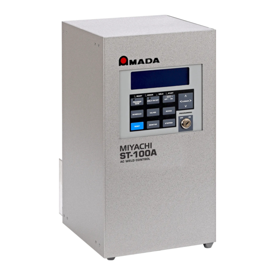
Amada ST-100A Operation Manual (146 pages)
AC WELDER
Brand:
Amada
| Category:
Welding System
| Size: 3 MB
Table of Contents
Table of Contents
4
Overview
17
Section I: Features
17
Optional Features
18
Standard Features
18
Major Components
19
Section II: Major Components
19
Error
21
Front Panel Controls and Indicators
21
LCD Display
21
Program/Save
21
Ready
21
Start
21
Weld
21
Data + on | off
22
Modes
22
Monitor
22
Reset
22
Schedule
22
Stepper
22
Valves
22
Weld ON/OFF
22
Cursor
23
Programming Lock
23
External Connectors
24
Cylinder Air Hose Connections
25
Internal Access
25
Electrical Connections
26
Option Cards
26
Cooling Water Requirements
27
Environmental Factors
27
Power Requirements
27
Space and Mounting Requirements
27
Connecting Electrical Power
28
Installation
28
Mounting the Power Supply
28
Section II: Power Supply Set-Up
28
Unpacking
28
Cooling Water Hose Connections
29
Input / Output Signal Connections
29
Placement of Secondary Current Coils
29
Secondary Current Sensing
29
Valve Transformer Wiring Connections
29
Chapter 3. Using ST-100A / ST-200A Control Functions Section I: Overview
31
Section II: Schedule Screen
32
Schedule
32
Program/Save
32
Links
32
SQD (Squeeze Delay)
32
CO (Cool Time)
33
W2 (Weld 2 Time)
33
Off
33
Current Setting
33
Control Mode
33
Force Output Channel)
33
Force
33
SCR # (SCR Number)
33
IMPULSE (Quantity of Weld 2 Operations)
33
COPY to # - Copying a Schedule
34
Section III: Valves Screen
35
Schedule
35
Program/Save
35
Electrode Valve 01
35
Status
35
Count
35
Section IV: Monitor Screen
36
CURR (Weld Current)
36
COND (Conduction Angle)
36
Volts
36
Force(Lb.)
36
LO (Low Current Limit)
36
HI (High Current Limit)
36
Fire
36
Counts (MONITOR COUNTS Screen)
37
Section V: Monitor Counts Screen
38
SCHEDULE # (Schedule Number)
38
Weld Count
38
Weld Count Limit
38
Set Weld Count=0
38
Step Count
38
Elect.valve
38
Section VI: Mode Screen
39
SCHEDULE # (Schedule Number)
39
Program/Save
39
Start
39
Weld Mode
40
Spot Weld Mode
40
Repeat Mode
40
Successive Mode
40
Chaining Mode
40
Linked Sched
41
Section VII: Linked Schedules Screen
42
Reference Number
42
Schd
42
CURR WELD CNT (Weld Counts for Schedule)
42
Weld Mode
42
Error
42
Section VIII: System Values Screens
43
System Values Screen 1
43
Turns Ratio
43
CNTRL MODE (Control Mode)
43
BIN. SCHED. SELECT (Binary Schedule Select)
43
Firing Switch
43
Coil
43
Contrast
43
NUM VALVES (Number of Valves)
44
Valves Status
44
Mode
44
MORE (System Value Screen 2)
44
System Values Screen 2
44
87° DELAY (on or OFF)
44
End Output
44
Step End Output
44
Weld On/Off
44
Low Line Alarm
44
Error Output
45
Set Defaults
45
Host Cntl
45
Unit Address
45
System Values Screen 3
45
Retraction
45
Pressure Switch
46
Force Calibration
46
Output Force
46
Monitored Volts
46
Monitored Time
46
DIF Pressure
46
Back Pressure
46
Screen 2
46
Section IX. System Valve Status Screen
47
VALVE (Valve Numbers)
47
CNT (Weld Count)
47
RESET (Reset Count to Zero)
47
SCR (SCR Used with each Valve)
47
Section X: Force Calibration Screen
48
Section XI. Stepper Screen
49
Valve Num
49
SCR# (SCR Number)
49
Stepper (On/Off)
49
Count
49
Heat
49
Chapter 4. Operating Instructions
51
Section I: Introduction
51
Overview
51
General Operator Safety
51
Section II: Preparing for Operation
52
Turning the Equipment on
52
Pre-Operational Setup
53
Section III: Setup Messages
54
Section IV. Operation
56
Spot Welds
57
Continuous Seam Weld
58
Cascading (Multiple Scrs)
59
Section V: Operational Messages
61
Major Run-Time Error Messages
61
Minor Run-Time Error Messages
63
Section VI: Shutdown
65
Emergency Shutdown
65
Normal Shutdown
65
Chapter 5. Maintenance Section I: Precautions
67
Section II: General Information
67
General Maintenance Procedures
67
Cooling Maintenance-Water Draining
67
Fuse Replacement
68
Principles of Operation
68
Wiring Diagram
69
Section III. Standard Components Replacement
71
AC Timer Main Board
71
Power Transformer T1
73
Power Transformer T2
73
Valve Transformer, T3
73
Surge Resistors
73
Snubber
74
SCR Drive Board
74
Control Panel Assembly
75
Section IV. Optional Components Replacement
76
Optional Primary Current Sensor
76
Optional Secondary Current Sensor Connector
76
Optional Key Lock
77
Optional SCR Assembly, 600,1200, 1800, and 2200 Amp
77
Section V. Spare Parts
78
Section VI. Repair
79
Section VII. Storage and Shipment
79
Preparation for Storage or Shipment
79
Packing for Storage or Shipment
79
Appendix A. Technical Specifications
81
Appendix B. Electrical and Data Connections
85
Appendix Cscr, Wire Gauge, and Circuit Breaker Selection
93
Appendix D. System Timing
97
Appendix E. Cascade Board Option
105
Appendix F. Valve Expansion Board Option
107
Appendix G. Voltage Monitor Board Option
109
Appendix H. Force Control Option
112
Appendix I. Pressure Monitoring Option
113
Appendix J. Communications Option
117
Appendix K. Circuit Modification for External Transformer Thermostat
139
Appendix L. Default Initializations
142
Advertisement
Advertisement
Related Products
Amada Miyachi Unitek STA-200A
Amada Miyachi Unitek STA-100A
Amada ST-200A
Amada SDEW3025
Amada S-2200CA
Amada S-4500CA
Amada SR-071A
Amada SR-072A
Amada SR-073A
Amada SIH-04CA05m
Amada Categories
Welding System
Welding Accessories
Power Supply
Indoor Furnishing
Transformer
More Amada Manuals
Login
Sign In
OR
Sign in with Facebook
Sign in with Google
Upload manual
Upload from disk
Upload from URL