Table of Contents
Advertisement
nordictrack.com
Model No. NTEX91022.0
Serial No.
Write the serial number in the space
above for reference.
Serial
Number
Decal
REGISTER YOUR
PRODUCT
To register your product and
activate your warranty today,
go to my.nordictrack.com.
MEMBER CARE
For service at any time, go to
support.nordictrack.com.
Or call 1-833-680-IFIT
(1-833-680-4348)
Mon.–Fri. 6 a.m.–6 p.m. MT
Sat. 8 a.m.–12 p.m. MT
Please do not contact the store.
CAUTION
Read all precautions and
instructions in this manual before
using this equipment. Keep this
manual for future reference.
USER'S MANUAL
Advertisement
Table of Contents

Related Manuals for NordicTrack STUDIO BIKE 1000


Summary of Contents for NordicTrack STUDIO BIKE 1000
- Page 1 Serial Number Decal REGISTER YOUR PRODUCT To register your product and activate your warranty today, go to my.nordictrack.com. MEMBER CARE For service at any time, go to support.nordictrack.com. Or call 1-833-680-IFIT (1-833-680-4348) Mon.–Fri. 6 a.m.–6 p.m. MT Sat. 8 a.m.–12 p.m. MT Please do not contact the store.
-
Page 2: Table Of Contents
Apply the decal in the location shown. Note: The decal(s) may not be shown at actual size. NORDICTRACK and IFIT are registered trademarks of ICON Health & Fitness, Inc. The Bluetooth ® word mark and logos are registered trademarks of Bluetooth SIG, Inc. and are used under license. Google Maps is a trade- mark of Google LLC. -
Page 3: Important Precautions
IMPORTANT PRECAUTIONS WARNING: To reduce the risk of serious injury, read all important precautions and instructions in this manual and all warnings on your exercise bike before using your exercise bike. ICON assumes no responsibility for personal injury or property damage sustained by or through the use of this product. - Page 4 STANDARD SERVICE PLANS...
-
Page 5: Before You Begin
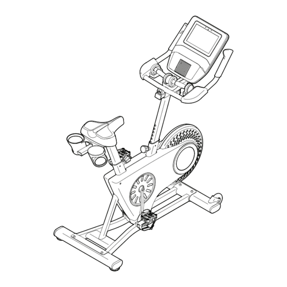
The STUDIO BIKE 1000 exercise bike provides decal are shown on the front cover of this manual. a selection of features designed to make your workouts at home more effective and enjoyable. -
Page 6: Part Identification Chart
PART IDENTIFICATION CHART Use the drawings below to identify the small parts needed for assembly. The number in parentheses below each drawing is the key number of the part, from the PART LIST near the end of this manual. The number following the key number is the quantity needed for assembly. -
Page 7: Assembly
• Left parts are marked “L” or “Left” and right parts power tools. are marked “R” or “Right.” • To identify small parts, see page 6. 1. Go to my.nordictrack.com on your computer and register your product. • documents your ownership • activates your warranty •... - Page 8 3. If there is a shipping support attached to the front of the Frame (1), remove the screws from the shipping support, and discard the screws and the shipping support. Attach the Front Stabilizer (22) to the Frame (1) with two M10 x 58mm Screws (74). 4.
- Page 9 6. Locate the Post Knob (47) on the rear of the Frame (1). Loosen and pull the Post Knob. Next, orient a Post Bushing (42) as shown, and insert it into the Frame (1). Make sure that the tabs (A) on the Post Bushing are in the holes (B) in the Frame.
- Page 10 8. If there is a shipping support attached to the Frame (1), remove and discard the shipping support. Orient a Post Bushing (42) as shown and hold it near the Frame (1). Insert the Main Wire (68) upward through the Post Bushing. Next, locate the Post Knob (47) on the front of the Frame (1).
- Page 11 10. Tip: Avoid pinching the Main Wire (68) during this step. Pull the Post Knob (47). Next, insert the Handlebar Post (6) into the Frame (1), and release the Post Knob into the lowest adjust- ment hole (G) in the Handlebar Post. Then, tighten the Post Knob.
- Page 12 12. Hold the Console Bracket (33) near the Handlebar Carriage (16). Insert the Main Wire (68) upward through the Console Bracket as Avoid pinching the shown. Main Wire (68) Tip: Avoid pinching the Main Wire (68). Attach the Console Bracket (33) to the Handlebar Carriage (16) with three M6 x 16mm Screws (72);...
- Page 13 15. Set the two Hand Weights (87) on the Right and Left Armrests (59, 69) and on the Hand Weight Rest (49). IMPORTANT: Make sure not to hit the Console (9) with the Hand Weights (87) when you pick up and set down the Hand Weights. 16.
-
Page 14: How To Use The Exercise Bike
HOW TO USE THE EXERCISE BIKE HOW TO PLUG IN THE POWER ADAPTER How to Adjust the Seat Carriage IMPORTANT: If the exercise bike has been exposed To adjust the to cold temperatures, allow it to warm to room tem- position of the seat perature before you plug in the power adapter (A). - Page 15 HOW TO USE THE PEDALS How to Use the Clip-in Side of the Pedals Note: You can remove the pedals and attach your To use the clip-in side of the pedals, you must wear own pedals to the exercise bike if desired. cycling shoes and the included cleats must be attached to your cycling shoes.
-
Page 16: How To Use The Console
HOW TO USE THE CONSOLE CONSOLE DIAGRAM FEATURES OF THE CONSOLE When you use the manual mode of the console, you can change the resistance of the pedals with the touch The advanced console offers an array of features of a button. designed to make your workouts more effective and enjoyable. - Page 17 HOW TO TURN ON THE CONSOLE HOW TO USE THE TOUCH SCREEN The included power adapter must be used to operate The console features a tablet with a full-color touch the exercise bike. See HOW TO PLUG IN THE screen. The following information will help you use the POWER ADAPTER on page 14.
- Page 18 HOW TO SET UP THE CONSOLE 4. Check for firmware updates. Before you use the exercise bike for the first time, set First, touch the menu button (three horizontal lines up the console. symbol), touch Settings, touch Maintenance, and then touch Update. The console will check for firm- 1.
- Page 19 HOW TO USE THE MANUAL MODE Touch the various workout information displays to view more options. Touch the more button (+ sym- 1. Touch the screen or press any button on the bol) to view statistics or charts. Touch the screen in console to turn on the console.
- Page 20 6. Turn on the fan if desired. THE OPTIONAL HEART RATE MONITOR The fan has several speed Whether your settings, including an auto goal is to mode. While the auto mode burn fat or to is selected, the speed of the strengthen your fan will automatically increase cardiovascular...
- Page 21 HOW TO USE A FEATURED WORKOUT When you select a workout, the screen will show an overview of the workout that includes details To use a featured workout, the console must be con- such as the duration and distance of the workout nected to a wireless network (see HOW TO CONNECT and the approximate number of calories you will TO A WIRELESS NETWORK on page 27).
- Page 22 IMPORTANT: The calorie goal shown in the 5. Wear headphones if desired. workout description is an estimate of the number of calories that you will burn during To connect your headphones to the console, first the workout. The actual number of calories that turn on your headphones, place them in pairing you burn will depend on various factors, such mode, and place them near the console.
- Page 23 HOW TO CREATE A DRAW-YOUR-OWN-MAP If you make a mistake, touch Undo in the map WORKOUT options. 1. Touch the screen or press any button on the The screen will display the elevation and distance console to turn on the console. statistics for your workout.
- Page 24 HOW TO USE AN IFIT WORKOUT 4. Select an iFIT workout from the home screen or the workout library. To use an iFIT workout, you must be logged into your iFIT account (see step 3 below) and the console Touch the buttons at the bottom of the screen to must be connected to a wireless network (see HOW select either the home screen (Home button) or the TO CONNECT TO A WIRELESS NETWORK on...
- Page 25 6. Create a list of favorite iFIT workouts if desired. When your headphones and the console pair successfully, the audio from the console will play To mark an iFIT workout as a favorite, simply view through your headphones. the overview or workout summary of the desired iFIT workout and touch the favorites button (heart 9.
- Page 26 HOW TO CHANGE CONSOLE SETTINGS Equipment • Equipment Info IMPORTANT: Firmware updates are always • Equipment Settings designed to improve your exercise experience. As a • Maintenance result, new settings and features may not be described • Wi-Fi in this manual. Take time to explore the console to learn how new settings and features work.
- Page 27 The screen will show the progress of the update. 3. Enable Wi-Fi. When the update is complete, the console will turn off and then turn back on. If it does not, unplug the Make sure that Wi-Fi ® is enabled. If it is not power adapter, wait for several seconds, and then enabled, touch the Wi-Fi toggle to enable it.
-
Page 28: Fcc Information
FCC INFORMATION This equipment has been tested and found to comply with the limits for a Class B digital device, pursuant to part 15 of the FCC Rules. These limits are designed to provide reasonable protection against harmful interference in a residential installation. This equipment generates, uses, and can radiate radio frequency energy and, if not installed and used in accordance with the instructions, may cause harmful interference to radio communications. -
Page 29: Maintenance And Troubleshooting
MAINTENANCE AND TROUBLESHOOTING HOW TO MAINTAIN THE EXERCISE BIKE HOW TO ADJUST THE REED SWITCH Regular maintenance is important for optimal If the console does not display accurate feedback, the performance and to reduce wear. Inspect and properly reed switch should be adjusted. Before you adjust the tighten all parts each time the exercise bike is used. - Page 30 HOW TO ADJUST THE DRIVE BELT If the pedals slip while you are pedaling, the drive belt may need to be adjusted. Before you adjust the drive belt, unplug the power adapter. Next, insert a standard screwdriver under the Right Shield Ring (19) in the location shown by the arrow, and gently pry the Right Shield Ring off the Right Shield (12).
-
Page 31: Exercise Guidelines
EXERCISE GUIDELINES Aerobic Exercise—If your goal is to strengthen your WARNING: cardiovascular system, you must perform aerobic Before beginning this exercise, which is activity that requires large amounts or any exercise program, consult your physi- of oxygen for prolonged periods of time. For aerobic cian. - Page 32 SUGGESTED STRETCHES The correct form for several basic stretches is shown at the right. Move slowly as you stretch; never bounce. 1. Toe Touch Stretch Stand with your knees bent slightly and slowly bend forward from your hips. Allow your back and shoulders to relax as you reach down toward your toes as far as possible.
-
Page 33: Part List
PART LIST Model No. NTEX91022.0 R0721B Key No. Qty. Description Key No. Qty. Description Frame Left Pivot Cover Power Wire/Receptacle Post Knob Seat Post Wheel Spacer Seat Carriage Hand Weight Rest Seat Right Grip Handlebar Post M4 x 22mm Screw Handlebar M4 x 10mm Screw Water Bottle Holder... -
Page 34: Exploded Drawing
EXPLODED DRAWING A Model No. NTEX91022.0 R0721B... - Page 35 EXPLODED DRAWING B Model No. NTEX91022.0 R0721B...
-
Page 36: Ordering Replacement Parts
ORDERING REPLACEMENT PARTS To order replacement parts, please see the front cover of this manual. To help us assist you, be prepared to provide the following information when contacting us: • the model number and serial number of the product (see the front cover of this manual) •...
Need help?
Do you have a question about the STUDIO BIKE 1000 and is the answer not in the manual?
Questions and answers