Advertisement
Quick Links
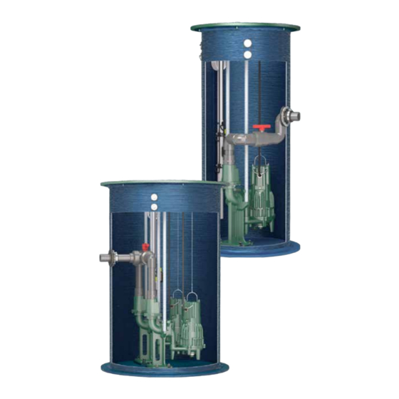
QLS – Q
Zoeller Pump Prefabricated Lift Station
Step #1
Confirm all components are included and there is no shipping damage. If you are
missing components or assume there is damage, please contact the distributor
where the lift station was purchased. Familiarize yourself with the instruction
manuals for each component (pump, controls, basin, etc.) prior to installation.
Place SYSTEM ID STICKER inside the door of the control panel for future reference.
Step #2
Confirm that the proper electrical power (for both PUMPS and CONTROLS) has
been provided to the jobsite by a licensed electrician. All wiring and conduit
must meet the NEC, local, and regional codes. For a single phase system, it is
recommended that separate incoming power sources be brought to the "pump" and the 115 volt "alarm & control"
circuits. On a three phase system, the circuits are isolated with a multi-tap transformer, therefore only one power
source need be brought to the panel.
Step #3
Properly excavate the pit being careful not to disturb any underground utilities or existing structure. Pit should be
a minimum 24" larger than the basin diameter. Make sure to adhere to all local/national building and safety codes.
Basin install requires the use of a compacted sub-base or concrete pad.
•
DO NOT DROP, IMPACT, OR ROLL BASIN
•
DO NOT WRAP CABLE OR CHAIN AROUND BASIN
Step #4
Measure, cut and align all inlet, electrical and discharge piping. Properly test fit and glue all discharge, inlet hubs
and electrical conduit couplings. Inspect ALL connections on the exterior of the basin. Use a hole saw one inch
larger than the pipe seal size to drill into the side of the basin at the correct elevation to properly install the pipe seal
hub assembly (follow the directions on your hub, if the inlet fitting provided is not a pipe seal).
Step #5
Backfill pit surrounding the basin with appropriate gravel (minimum 12" from basin wall). Basin should be filled
with water prior to pouring a concrete anchor around anti-floatation device. Backfill and subbase should be 1/8"-
3/4" pea gravel or 1/8"- 3/4" crushed stone. See drawing (SK 2280) on next page.
Step #6
Backfill grade with gravel and fill dirt or to specifying engineer's design. See basin drawing (SK 2280) on next page.
S
UICK
FOLLOW ALL SAFETY GUIDELINES
These guidelines and installations are to ensure that damage or premature failure to the system does not occur. The QWIK Start Guide is NOT
designed to be a replacement for all installation instructions. Safe and proper installation procedures shall be the responsibility of the installer.
For any questions, contact Zoeller's Product Support Department at 1(800)928-7867 ext. #6 OR zcotechnical@zoeller.com.
TART GUIDE
FM3058
SYSTEM ID STICKER SAMPLE
Advertisement

Related Manuals for Zoeller QLS Series


Summary of Contents for Zoeller QLS Series
- Page 1 These guidelines and installations are to ensure that damage or premature failure to the system does not occur. The QWIK Start Guide is NOT designed to be a replacement for all installation instructions. Safe and proper installation procedures shall be the responsibility of the installer. For any questions, contact Zoeller’s Product Support Department at 1(800)928-7867 ext. #6 OR zcotechnical@zoeller.com.
- Page 2 Three - Way Ball Valve Flow indicates closed. (Used with Duplex Systems) All open Left closed Discharge closed Right closed © Copyright 2017 Zoeller ® Co. All rights reserved. 502-778-2731 | 800-928-7867 | 3649 Cane Run Road | Louisville, KY 40211-1961 | www.zoellerpumps.com...
Need help?
Do you have a question about the QLS Series and is the answer not in the manual?
Questions and answers