Table of Contents
Advertisement
Quick Links
EVK-R41Z
Evaluation kit for R41Z modules
User guide
Abstract
This document describes how to set up the EVK-R41Z evaluation kit to evaluate R41Z series
modules. It also describes the different options for debugging and the development capabilities
included in the evaluation board.
www.u-blox.com
UBX-19033357 - R03
Advertisement
Table of Contents

Subscribe to Our Youtube Channel
Related Manuals for Ublox EVK-R41Z


Summary of Contents for Ublox EVK-R41Z
- Page 1 Evaluation kit for R41Z modules User guide Abstract This document describes how to set up the EVK-R41Z evaluation kit to evaluate R41Z series modules. It also describes the different options for debugging and the development capabilities included in the evaluation board.
-
Page 2: Document Information
EVK-R41Z - User guide Document information Title EVK-R41Z Subtitle Evaluation kit for R41Z modules Document type User guide Document number UBX-19033357 Revision and date 5-Nov-2019 Disclosure restriction This document applies to the following products: Product name Type number R41Z-Eval R41Z-Eval-00 u-blox or third parties may hold intellectual property rights in the products, names, logos and designs included in this document. -
Page 3: Table Of Contents
EVK-R41Z - User guide Contents Document information ..........................2 Contents ................................3 Product description ..........................4 1.1 Key features ..............................4 1.2 Kit includes ..............................5 1.3 Development tools ............................5 Hardware description ........................... 6 2.1 Power ................................6 2.2 R41Z power modes ............................. 7 2.2.1 Power configuration switch ...................... -
Page 4: Product Description
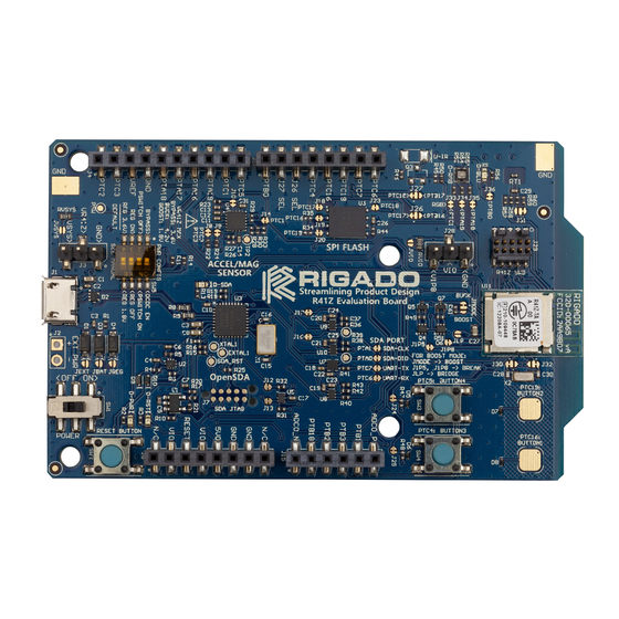
• Provision for IR LED • 32.768 kHz crystal • CR2032 battery holder • Supports all DC-DC modes of the R41Z module • Adjustable output regulator simplifies development Figure 1: EVK-R41Z evaluation board (Top view) UBX-19033357 - R03 Product description Page 4 of 23... -
Page 5: Kit Includes
EVK-R41Z - User guide 1.2 Kit includes R41Z evaluation kit includes: • R41Z evaluation board • Micro-USB cable • Quick start guide 1.3 Development tools The tools listed below will aid in development with the R41Z modules. Not all tools will be required depending on which software suite is used. -
Page 6: Hardware Description
EVK-R41Z - User guide Hardware description Design files for the R41Z evaluation kit can be obtained from your u-blox sales representative. Breakout Accelerometer / SPI Flash IR-LED RGB and Blue Headers Magnetometer Sensor Module Provision User LEDs Power Thermistor Configuration... -
Page 7: R41Z Power Modes
EVK-R41Z - User guide Figure 3: Schematic: Power supply 2.2 R41Z power modes The R41Z module contains a DC-DC converter that allows it to operate in a variety of power environments. The R41Z evaluation board supports all these operating modes, which are... -
Page 8: Power Configuration Switch
EVK-R41Z - User guide 2.2.1 Power configuration switch The power configuration switch allows easy and quick adjustment of most power settings on the R41Z evaluation board. Figure 4: Power configuration switch SW position Default (SW position off) Option (SW position on) Bypass Power Mode DC-DC Power Mode. -
Page 9: Measuring Power Consumption
EVK-R41Z - User guide The 4 jumpers used to switch between Buck and Boost DC-DC modes are labeled JMODE, JLP, J1P5, and J1P8. See the figures below for how to set these jumpers along with the correct Power Configuration Switch positions. -
Page 10: Debug Interface
EVK-R41Z - User guide Figure 7: Schematic: Current measurement headers 2.3 Debug interface The R41Z evaluation board features an OpenSDA 2.1 interface which includes a SWD connection and virtual COM port for easy programming and debugging of the R41Z module. -
Page 11: External Debug Header
EVK-R41Z - User guide Figure 8: Schematic: Reset button 2.3.3 External debug header In addition to the onboard OpenSDA interface, the R41Z evaluation board supports the use of external debuggers. A standard 10-pin SWD/JTAG header is provided with the following... -
Page 12: Expansion Headers
EVK-R41Z - User guide 2.4.1 Expansion headers Figure 9: Expansion header pinout 2.4.2 IR LED Provision An unpopulated position for an IR LED and driver transistor are provided on the evaluation board. If IR is part the application under development, these parts can be populated by the end user. -
Page 13: User Leds
EVK-R41Z - User guide 2.4.3 User LEDs The R41Z evaluation board features an RGB LED and a separate blue LED. Since the GPIO used are shared with the expansion header, solder jumpers are provided to disconnect the LEDs if required. Since the LEDs are powered from the peripheral power bus VIO, they will be powered directly by the R41Z module when it is operating in either Buck or Boost DC-DC mode. -
Page 14: Spi Flash
EVK-R41Z - User guide Figure 13: Schematic: User buttons 2.4.6 SPI flash To assist development of applications requiring external storage, a 4 Mbit flash module is provided (Adesto Tech. AT45DB041E-MHN2B-T). The flash uses an SPI interface with signals shared with the expansion headers. When using multiple Chip Select (CS) signals, this allows the same SPI bus to be used with both the Flash module and one or more SPI devices on an expansion shield. -
Page 15: R41Z Module
EVK-R41Z - User guide Address 0x1C 0x1D 0x1E 0x1F (Default) Table 7: Combo sensor addresses Signal R41Z I/O Interrupt PTC1 SCLK PTC2 PTC3 Table 8: I2C sensor signals Figure 15: Schematic: I2C combo sensor 2.5 R41Z module For details on the R41Z module, see the R41Z data sheet. The R41Z module is an industry leading Bluetooth low energy and IEEE 802.15.4 pre-certified module with a wide range of... -
Page 16: Setting Up The Evaluation Board
EVK-R41Z - User guide Setting up the evaluation board This section provides information on how to set up and program the R41Z evaluation kit with an example application. ☞ This process will erase any preloaded firmware provided by u-blox including bootloader and demonstration firmware, if provided. -
Page 17: Try An Example
EVK-R41Z - User guide 3.2 Try an example Import and run an example from the SDK. 1. In the lower left pane, click “Import SDK example(s)…”. Figure 18: Import example 2. Click the “frdmkw41z” under “Available boards”, then click “Next”. - Page 18 EVK-R41Z - User guide 3. On the next screen, select the example, then click Finish. In this case, we will use the “Bluetooth beacon”. Figure 20: Select Bluetooth beacon example 4. Application source code is in the project tree under the “source” directory: Figure 21: Example source code 5.
- Page 19 EVK-R41Z - User guide 6. Click the blue “bug” icon to start debugging: Figure 23: Start debugging Select the “J-Link OpenSDA” debug probe and click OK: Figure 24: Debug probe selection 7. Accept the OpenSDA terms of use: UBX-19033357 - R03...
- Page 20 EVK-R41Z - User guide Figure 25: OpenSDA terms of use Click the “Play” icon to run the application: Figure 26: Run the example 10. Observe the blue LED flashing on the R41Z-EVAL board: Figure 27: Flashing LED UBX-19033357 - R03...
- Page 21 EVK-R41Z - User guide 11. Open the NXP IoT Toolbox mobile app on your mobile device, and tap the “Beacons” icon: Figure 28: NXP IoT toolbox mobile app 12. See the beacon RSSI increase as you move the mobile device closer to the R41Z-EVAL.
-
Page 22: Related Documents
EVK-R41Z - User guide Related documents R41Z module product summary, doc. no. UBX-19033358 R41Z module data sheet, doc. no. UBX-19033355 u-blox package information guide, doc. no. UBX-14001652 NXP KW41Z Fact sheet NXP BLE Mobile toolbox NXP KW41Z Data sheet NXP KW41Z Reference manual NXP KW41Z Errata ☞... -
Page 23: Contact
EVK-R41Z - User guide Contact For complete contact information, visit us at www.u-blox.com. u-blox Offices North, Central and South America Headquarters Asia, Australia, Pacific Europe, Middle East, Africa u-blox America, Inc. u-blox Singapore Pte. Ltd. u-blox AG Phone: +1 703 483 3180...
Need help?
Do you have a question about the EVK-R41Z and is the answer not in the manual?
Questions and answers