Table of Contents
Advertisement
Quick Links
PD-IM-7401 Evaluation Board - User Guide
PD-IM-7401 Evaluation Board User Guide
Revision 1.0
Catalog Number: 06-0471-056
PRODUCTION DATA – Information contained in this document is proprietary to
Microsemi and is current as of publication date. This document may not be
modified in any way without the express written consent of Microsemi. Product
processing does not necessarily include testing of all parameters. Microsemi
reserves the right to change the configuration and performance of the product and
to discontinue product at any time.
Advertisement
Table of Contents

Related Manuals for Microsemi PD-IM-7401


Summary of Contents for Microsemi PD-IM-7401
- Page 1 Catalog Number: 06-0471-056 PRODUCTION DATA – Information contained in this document is proprietary to Microsemi and is current as of publication date. This document may not be modified in any way without the express written consent of Microsemi. Product processing does not necessarily include testing of all parameters. Microsemi reserves the right to change the configuration and performance of the product and to discontinue product at any time.
- Page 2 Application Note 184: Designing a 1 Port PoE system, Catalogue Number 06-0079-080 The above documents can be obtained via our Customer Support. To access other documents, go to our web site at http://www.microsemi.com/ and under Tech Support\Documentation, look up for the documents. Copyright © 2009...
-
Page 3: Table Of Contents
PD-IM-7401 Evaluation Board - User Guide Table of Contents ............................4 BOUT THIS UIDE 1.1 Audience ..............................4 1.2 Organization............................4 .............................. 5 NTRODUCTION 2.1 Evaluation Boards Ordering Information....................5 2.2 Evaluation Board Features........................5 2.3 Evaluation Board Interfaces and Connections..................6 2.4 Physical Characteristics .......................... -
Page 4: About This Guide
PD-IM-7401 Evaluation Board - User Guide 1 About this Guide This user guide provides both a description and operation procedures for Microsemi's PD-IM-7401 Evaluation Board, which is used to evaluate the performance of the PD69101 PoE applications. Audience This user guide is intended for qualified personnel, meaning operators and technicians who have a background in basic concepts of electronics. -
Page 5: Introduction
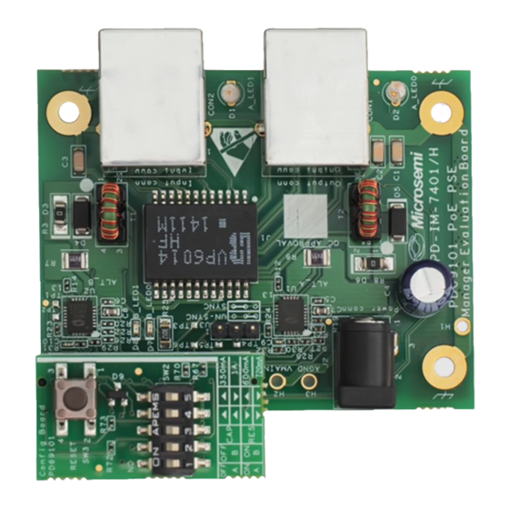
PD-IM-7401 Evaluation Board - User Guide 2 Introduction Microsemi’s PD-IM-7401 Evaluation Board (see Figure 1) provides the designer with the needed environment to evaluate the performance and the implementation of PoE applications based on the PD69101 PoE Manager. The evaluation board enables PoE designers to evaluate Microsemi's PoE solution with maximum flexibility and ease in... -
Page 6: Evaluation Board Interfaces And Connections
PD-IM-7401 Evaluation Board - User Guide Evaluation Board Interfaces and Connections The board has several interfaces: RJ45 interface: Running from the PD69101 to PD (powered device) (CON1) Vin connectors: DC in (Vmain) connection (J2) Configuration interface: Control and configuration signals running between the main board... -
Page 7: Physical Description
Upon opening the Evaluation Board package, verify that all parts itemized in the packing list are included. If any part is missing or seems damaged, contact the local representative or Microsemi's Headquarters. Package contents for standard shipments are as follows:... -
Page 8: Reset Button
PD-IM-7401 Evaluation Board - User Guide 3.3.1 Reset Button The dedicated Reset button SW #1 (see Figure 4) is utilized to reset the PD69101 PoE controllers. Figure 4: Reset Button (SW #3) 3.3.2 Configuration Switches Five configuration switches are utilized to configure the PD69101 PoE controllers operations: Two ON/OFF switches are utilized to enable/disable the Master and the Slave (SW #1 and SW #2) (see Table 3). -
Page 9: Connectors
PD-IM-7401 Evaluation Board - User Guide Figure 5: Configuration Switches (SW #2) Connectors The following sections provide both general and detailed information regarding the unit connectors. 3.4.1 Connectors Table Table 5 lists the Evaluation Board's connectors. Table 5: Connectors List... - Page 10 PD-IM-7401 Evaluation Board - User Guide Manufacture part number: 3060115907 Figure 6: RJ45 Connectors 2. Vin connectors (J2) See Figure 7. DC in (Vmain) connection, used to power the Evaluation Board, 44 V > Vmain > 57 VDC Table 7: Vin Connectors Pin No.
- Page 11 PD-IM-7401 Evaluation Board - User Guide 3. LEDs Indication See Figure 8. These are port status indication LEDs. Two dedicated LEDs indicate the port status (for example on/off): D1 and Figure 8: LEDs Indication Copyright © 2009 Page 11 Microsemi Rev.
-
Page 12: Electrical Characteristics
PD-IM-7401 Evaluation Board - User Guide 4 Electrical Characteristics The evaluation board’s electrical characteristics are described below: Table 8: Electrical Characteristics Parameter Symbol Min. Max. Units Main DC supply Vmain Port Isolation to chassis kVrms All communication's Isolation to kVrms chassis Copyright ©... -
Page 13: Installation
PD-IM-7401 Evaluation Board - User Guide 5 Installation This chapter describes the steps required to install and operate the Evaluation Board with any PoE application. Preliminary Considerations and Safety Precautions Verify that the board's power supply is turned on before the peripheral devices are turned on. - Page 14 Microsemi and cannot be copied, published, uploaded, posted, transmitted, distributed or disclosed or used without the express duly signed written consent of Microsemi If the recipient of this document has entered into a disclosure agreement with Microsemi, then the terms of such Agreement will also apply .
Need help?
Do you have a question about the PD-IM-7401 and is the answer not in the manual?
Questions and answers