Inovance MD800 Series Function Manual
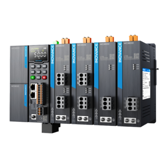
Ac drive multidrive system
Hide thumbs
Also See for MD800 Series:
- Function manual (565 pages) ,
- Quick start manual (145 pages) ,
- Manual (132 pages)
Table of Contents
Advertisement
Advertisement
Table of Contents

Subscribe to Our Youtube Channel
Related Manuals for Inovance MD800 Series


Summary of Contents for Inovance MD800 Series
-
Page 2: Preface
Preface Introduction The MD800 series is a new generation of standard AC drive (multidrive system) designed for low-power multidrive applications in the traditional original equipment manufacturer (OEM) industry. It is widely applied in industries such as printing and packaging, woodworking machine tools, food and beverage, logistics and storage, textile printing and dyeing, and fans and water pumps. - Page 3 How to Obtain This guide is not delivered with the product. You can obtain the PDF version by the following method: http://en.inovance.cn/ Log in to Inovance's website ( ), choose Support > Download, search by keyword, and then download the PDF file.
-
Page 4: Table Of Contents
Table of Contents T T a a b b l l e e o o f f C C o o n n t t e e n n t t s s Preface..................... 1 List of Power Supply Unit Parameters............... 8 1 Power Supply Unit Parameters .............. - Page 5 Table of Contents 2.7 F6: Start/Stop Control Parameters ............294 2.8 F7: Operating Panel and Display Parameters .
- Page 6 Table of Contents 4 Function Applications ................474 4.1 Drive Configuration ................474 4.1.1 Operation Command Sources .
- Page 7 Table of Contents 4.3.4.2 Functions of Analog or Temperature Input Terminals ......522 4.3.4.3 Functions of AI Terminals .
- Page 8 Table of Contents 4.5.9.1 Function Description ............. . 563 4.5.9.2 Related Parameters .
-
Page 9: List Of Power Supply Unit Parameters
List of Power Supply Unit Parameters List of Power Supply Unit Parameters Table –1 List of function parameters of the power supply unit Para. Para. Name Page Address Value Range Default Unit Change F0-01 0xF001 800 to 800 F0-01 Product SN Unchangeable ”... - Page 10 List of Power Supply Unit Parameters Para. Para. Name Page Address Value Range Default Unit Change 6: Power supply unit - DIO2 7: Power supply unit - DIO3 8: Power supply unit - DIO4 101: Extension card 1 - 102: Extension card 1 - 103: Extension card 1 - 104: Extension card 1 - 105: Extension card 1 -...
- Page 11 List of Power Supply Unit Parameters Para. Para. Name Page Address Value Range Default Unit Change 7: Coast-to-stop for drive unit 8: Stop-according-to- preset-mode for drive unit F4-02 F4-02 0xF402 Same as F4-00 At stop DI2 hardware source ” on page “...
- Page 12 List of Power Supply Unit Parameters Para. Para. Name Page Address Value Range Default Unit Change F4-21 0xF415 0.00s to 600.00s 0.00 F4-21 DI6 active delay In real time ” on page “ F4-22 F4-22 0xF416 DI7 active delay 0.00s to 600.00s 0.00 In real time ”...
- Page 13 List of Power Supply Unit Parameters Para. Para. Name Page Address Value Range Default Unit Change 2: Power supply unit - DIO2 3: Power supply unit - DIO3 4: Power supply unit - DIO4 5: Power supply unit - 101: Extension card 1 - DO1/RO1 102: Extension card 1 - DO2/RO2...
- Page 14 List of Power Supply Unit Parameters Para. Para. Name Page Address Value Range Default Unit Change 9: Three-phase input normal 10: IGBT overtemperature 11: IGBT overtemperature pre- warning 12: Communication control F5-02 F5-02 0xF502 Same as F5-00 At stop DO2/RO2 hardware ”...
- Page 15 List of Power Supply Unit Parameters Para. Para. Name Page Address Value Range Default Unit Change F5-20 0xF514 Ones: F5-20 DO/RO active mode In real time ” on page “ 0: Active high 1: Active low Tens: 0: Active high 1: Active low Hundreds: 0: Active high...
- Page 16 List of Power Supply Unit Parameters Para. Para. Name Page Address Value Range Default Unit Change FA-13 FA-13 0xFA0D Total power-on 0 h to 0 h Unchangeable ” on page “ duration (hour) upon the 5th fault FA-14 FA-14 0xFA0E Total power-on 0 min to 0 min Unchangeable...
- Page 17 List of Power Supply Unit Parameters Para. Para. Name Page Address Value Range Default Unit Change 0s to 0s FA-35 FA-35 0xFA23 Total power-on Unchangeable ” on page “ duration (second) upon the 4th fault FA-40 0xFA28 0 to 0 FA-40 Fault code of the 3rd Unchangeable...
- Page 18 List of Power Supply Unit Parameters Para. Para. Name Page Address Value Range Default Unit Change FA-62 0xFA3E 0.0 V to 0.0 V FA-62 Bus voltage upon Unchangeable ” on page “ the 2nd fault FA-63 FA-63 0xFA3F Heatsink 0°C to 0℃ °C Unchangeable ”...
- Page 19 List of Power Supply Unit Parameters Para. Para. Name Page Address Value Range Default Unit Change FA-84 0xFA54 FA-84 Ambient 0°C to 0℃ °C Unchangeable ” on page “ temperature upon the 1st fault FA-86 FA-86 0xFA56 Grid voltage Usr 0 V to 0 V Unchangeable ”...
- Page 20 List of Power Supply Unit Parameters Para. Para. Name Page Address Value Range Default Unit Change 0xFD02 1 to 127 Fd-02 RS485 local address Unchangeable Fd-02 ” on page “ 0xFD03 RS485 response 0 ms to 20 ms Fd-03 In real time Fd-03 ”...
- Page 21 List of Power Supply Unit Parameters Para. Para. Name Page Address Value Range Default Unit Change 0xFD11 Fd-17 Bus-off count per 0 to 65535 Unchangeable Fd-17 ” on page “ unit time 0xFD12 1 to 15 Fd-18 Power supply unit In real time Fd-18 ”...
- Page 22 List of Power Supply Unit Parameters Para. Para. Name Page Address Value Range Default Unit Change Fd-51 0xFD33 Network bridge data 0 ms to 65535 ms Unchangeable Fd-51 ” on page “ interaction period 0xFD34 0 to 30 Fd-52 Number of online Unchangeable Fd-52 ”...
- Page 23 List of Power Supply Unit Parameters Para. Para. Name Page Address Value Range Default Unit Change 0xFD4F Fd-79 EtherCAT 0 to 65535 In real time Fd-79 ” on page “ synchronization error monitoring mode Fd-80 0xFD50 EtherCAT 0 to 65535 Unchangeable Fd-80 ”...
- Page 24 List of Power Supply Unit Parameters Para. Para. Name Page Address Value Range Default Unit Change 0xFD61 Fd-97 Station number of 0 to 65535 Unchangeable Fd-97 ” on page “ device connected to reserved slot 5 Fd-98 0xFD62 0 to 65535 Unchangeable Fd-98 Station number of...
- Page 25 List of Power Supply Unit Parameters Para. Para. Name Page Address Value Range Default Unit Change FP-01 0x1F01 Parameter FP-01 0: No operation In real time ” on page “ initialization 1: Restore default settings 2: Clear records 4: Back up current user parameters 501: Restore user backup parameters...
- Page 26 List of Power Supply Unit Parameters Para. Para. Name Page Address Value Range Default Unit Change A0-04 0xA004 A0-04 Display of station Bit0: I/O extension card Unchangeable ” on page “ number of I/O extension card with Bit1: Extension card 2 frame loss Bit2: Extension card 3 A0-05...
- Page 27 List of Power Supply Unit Parameters Para. Para. Name Page Address Value Range Default Unit Change 3: PT1000 input 4: KTY84 input 5: PTC130 input A2-00 A2-00 0xA200 0.000s to 5.000s 0.010 Extension card 1 - In real time ” on page “...
- Page 28 List of Power Supply Unit Parameters Para. Para. Name Page Address Value Range Default Unit Change AC-00 0xAC00 0.000 V to 12.000 V 2.000 AC-00 Power supply unit - In real time ” on page “ AI1 measured voltage 1 AC-01 AC-01 0xAC01...
- Page 29 List of Power Supply Unit Parameters Para. Para. Name Page Address Value Range Default Unit Change AC-15 0xAC0F 0.000 V to 12.000 V 2.000 AC-15 Extension card 1 - In real time ” on page “ AI2 displayed voltage 2 AC-16 AC-16 0xAC10...
- Page 30 List of Power Supply Unit Parameters Para. Para. Name Page Address Value Range Default Unit Change 0.000 V to 12.000 V 2.000 AC-30 AC-30 0xAC1E Extension card 3 - In real time ” on page “ AI2 measured voltage 2 AC-31 AC-31 0xAC1F...
- Page 31 List of Power Supply Unit Parameters Para. Para. Name Page Address Value Range Default Unit Change AE-15 0xAE0F 0.000 V to 12.000 V 2.000 AE-15 Extension card 1 - In real time ” on page “ AI2 displayed voltage 2 AE-16 AE-16 0xAE10...
- Page 32 List of Power Supply Unit Parameters Para. Para. Name Page Address Value Range Default Unit Change 0.000 V to 12.000 V 2.000 AE-30 AE-30 0xAE1E Extension card 3 - In real time ” on page “ AI2 measured voltage 2 AE-31 AE-31 0xAE1F...
- Page 33 List of Power Supply Unit Parameters Para. Para. Name Page Address Value Range Default Unit Change AF-19 0xAF13 AF-19 RPDO3-SubIndex1-L 0 to 65535 In real time ” on page “ AF-20 AF-20 0xAF14 RPDO3-SubIndex2-H 0 to 65535 In real time ”...
- Page 34 List of Power Supply Unit Parameters Para. Para. Name Page Address Value Range Default Unit Change AF-40 0xAF28 AF-40 TPDO2-SubIndex0-H 0 to 65535 In real time ” on page “ AF-41 AF-41 0xAF29 TPDO2-SubIndex0-L 0 to 65535 In real time ”...
- Page 35 List of Power Supply Unit Parameters Para. Para. Name Page Address Value Range Default Unit Change AF-62 0xAF3E AF-62 TPDO4-SubIndex3-H 0 to 65535 In real time ” on page “ AF-63 AF-63 0xAF3F TPDO4-SubIndex3-L 0 to 65535 In real time ”...
- Page 36 List of Power Supply Unit Parameters Para. Para. Name Page Address Value Range Default Unit Change U0-22 0x7016 Current power-on U0-22 0s to 65535s Unchangeable ” on page “ duration (second) U0-23 U0-23 0x7017 Current power-on 0 ms to 65535 ms Unchangeable ”...
- Page 37 List of Power Supply Unit Parameters Para. Para. Name Page Address Value Range Default Unit Change U2-09 0x7209 U2-09 Local I/O - Available 0 to 65535 Unchangeable ” on page “ AO hardware resource U2-10 U2-10 0x720A Local I/O - DI input 0 to 65535 Unchangeable ”...
- Page 38 List of Power Supply Unit Parameters Para. Para. Name Page Address Value Range Default Unit Change U2-40 0x7228 U2-40 Local I/O - Condition 0 to 65535 Unchangeable ” on page “ of DO1 used by drive unit U2-41 U2-41 0x7229 Local I/O - Condition 0 to 65535 Unchangeable...
- Page 39 List of Power Supply Unit Parameters Para. Para. Name Page Address Value Range Default Unit Change U3-08 U3-08 0x7308 I/O extension card 1 0 to 65535 Unchangeable ” on page “ - Original AO hardware resource U3-09 U3-09 0x7309 I/O extension card 1 0 to 65535 Unchangeable ”...
- Page 40 List of Power Supply Unit Parameters Para. Para. Name Page Address Value Range Default Unit Change U3-30 U3-30 0x731E I/O extension card 1 0 to 65535 Unchangeable ” on page “ - Condition of AI1 used by drive unit U3-31 0x731F 0 to 65535 U3-31...
- Page 41 List of Power Supply Unit Parameters Para. Para. Name Page Address Value Range Default Unit Change U4-06 0x7406 U4-06 I/O extension card 2 0 to 65535 Unchangeable ” on page “ - Original DO hardware resource U4-07 U4-07 0x7407 I/O extension card 2 0 to 65535 Unchangeable ”...
- Page 42 List of Power Supply Unit Parameters Para. Para. Name Page Address Value Range Default Unit Change U4-26 0x741A U4-26 I/O extension card 2 0 to 65535 Unchangeable ” on page “ - Condition of DI7 used by drive unit U4-27 0x741B 0 to 65535 U4-27...
-
Page 43: Power Supply Unit Parameters
Power Supply Unit Parameters Power Supply Unit Parameters F0: Basic Parameters of Power Supply Unit F0-01 Product SN Effective mode: - 0xF001 Address: Min.: Unit: Max.: Data type: UInt16 Default: Change: Unchangeable Value Range: 800 to 800 Description MD800 F0-02 Software version Effective mode: - 0xF002... - Page 44 Power Supply Unit Parameters Min.: Unit: Max.: Data type: UInt16 Change: In real time Default: Value Range: 150 V to 440 V Description When the bus voltage is lower than the value of F1-00 (Bus undervoltage threshold), the system determines that undervoltage occurs. When the system is in undervoltage state, the drive unit fails to run.
- Page 45 Power Supply Unit Parameters F1-04 Braking transistor short circuit fault Effective mode: - 0xF104 Address: Min.: Unit: Max.: Data type: UInt16 Change: In real time Default: Value Range: 0: Disabled 1: Enabled Description When the braking transistor short circuit detection function is enabled, the system will report E61.01 or E61.03 if the braking transistor is short-circuited.
-
Page 46: F4: Input Terminal Parameters
Power Supply Unit Parameters Max.: Data type: UInt16 Change: In real time Default: Value Range: 0: Disabled 1: Enabled 2: Alarm Description This parameter defines the action upon a fan fault. When it is set to 1, E80.00 is reported when the fan is blocked or damaged. When it is set to 2, A80.00 is reported upon a fan fault. - Page 47 Power Supply Unit Parameters 202: Extension card 2 - DI2 203: Extension card 2 - DI3 204: Extension card 2 - DI4 205: Extension card 2 - DI5 206: Extension card 2 - DI6 207: Extension card 2 - DI7 208: Extension card 2 - DI8 Description This parameter defines the source of the input terminal.
- Page 48 Power Supply Unit Parameters F4-02 DI2 hardware source Effective mode: - 0xF402 Address: Min.: Unit: Max.: Data type: UInt16 At stop Change: Default: Value Range: 0: Not selected 1: Power supply unit - DI1 2: Power supply unit - DI2 3: Power supply unit - DI3 4: Power supply unit - DI4 5: Power supply unit - DIO1...
- Page 49 Power Supply Unit Parameters 8: Stop-according-to-preset-mode for drive unit Description Same as F4-01 F4-04 DI3 hardware source Effective mode: - 0xF404 Address: Min.: Unit: Max.: Data type: UInt16 At stop Change: Default: Value Range: 0: Not selected 1: Power supply unit - DI1 2: Power supply unit - DI2 3: Power supply unit - DI3 4: Power supply unit - DI4...
- Page 50 Power Supply Unit Parameters 5: Fault reset 6: Operation prohibition for drive unit 7: Coast-to-stop for drive unit 8: Stop-according-to-preset-mode for drive unit Description Same as F4-01 F4-06 DI4 hardware source Effective mode: - 0xF406 Address: Min.: Unit: Max.: Data type: UInt16 At stop Default:...
- Page 51 Power Supply Unit Parameters 1: Running enable 2: Incoming circuit breaker feedback 3: Auxiliary circuit breaker feedback 4: Residual current device feedback 5: Fault reset 6: Operation prohibition for drive unit 7: Coast-to-stop for drive unit 8: Stop-according-to-preset-mode for drive unit Description Same as F4-01 F4-08...
- Page 52 Power Supply Unit Parameters Max.: Data type: UInt16 At stop Change: Default: Value Range: 0: No function 1: Running enable 2: Incoming circuit breaker feedback 3: Auxiliary circuit breaker feedback 4: Residual current device feedback 5: Fault reset 6: Operation prohibition for drive unit 7: Coast-to-stop for drive unit 8: Stop-according-to-preset-mode for drive unit Description...
- Page 53 Power Supply Unit Parameters F4-11 DI6 function Effective mode: - 0xF40B Address: Min.: Unit: Max.: Data type: UInt16 At stop Change: Default: Value Range: 0: No function 1: Running enable 2: Incoming circuit breaker feedback 3: Auxiliary circuit breaker feedback 4: Residual current device feedback 5: Fault reset 6: Operation prohibition for drive unit...
- Page 54 Power Supply Unit Parameters 208: Extension card 2 - DI8 Description Same as F4-00 F4-13 DI7 function Effective mode: - 0xF40D Address: Min.: Unit: Max.: Data type: UInt16 At stop Default: Change: Value Range: 0: No function 1: Running enable 2: Incoming circuit breaker feedback 3: Auxiliary circuit breaker feedback 4: Residual current device feedback...
- Page 55 Power Supply Unit Parameters 204: Extension card 2 - DI4 205: Extension card 2 - DI5 206: Extension card 2 - DI6 207: Extension card 2 - DI7 208: Extension card 2 - DI8 Description Same as F4-00 F4-15 DI8 function Effective mode: - 0xF40F Address:...
- Page 56 Power Supply Unit Parameters Max.: 600.00 Data type: UInt16 0.00 Change: In real time Default: Value Range: 0.00s to 600.00s Description Same as F4-16 F4-19 DI4 active delay Effective mode: - Address: 0xF413 Min.: 0.00 Unit: Max.: 600.00 Data type: UInt16 0.00 Change:...
- Page 57 Power Supply Unit Parameters Value Range: 0.00s to 600.00s Description Same as F4-16 F4-24 DI1 inactive delay Effective mode: - Address: 0xF418 Min.: 0.00 Unit: Max.: 600.00 Data type: UInt16 0.00 Default: Change: In real time Value Range: 0.00s to 600.00s Description This parameter defines the delay of response to the DI terminal switching from the active state to inactive state.
- Page 58 Power Supply Unit Parameters 0.00s to 600.00s Description Same as F4-24 F4-29 DI6 inactive delay Effective mode: - 0xF41D Address: Min.: 0.00 Unit: Max.: 600.00 Data type: UInt16 0.00 Default: Change: In real time Value Range: 0.00s to 600.00s Description Same as F4-24 F4-30 DI7 inactive delay...
- Page 59 Power Supply Unit Parameters Thousands: 0: Active low 1: Active high Ten thousands: 0: Active low 1: Active high Description When active high is selected, the DI terminal is active when connected to COM and inactive when disconnected from COM. When active low is selected, the DI terminal is inactive when connected to COM and active when disconnected from COM.
-
Page 60: F5: Output Terminal Parameters
Power Supply Unit Parameters F5: Output Terminal Parameters F5-00 DO1/RO1 hardware source Effective mode: - 0xF500 Address: Min.: Unit: Max.: Data type: UInt16 At stop Default: Change: Value Range: 0: Not selected 1: Power supply unit - DIO1 2: Power supply unit - DIO2 3: Power supply unit - DIO3 4: Power supply unit - DIO4 5: Power supply unit - RO1... - Page 61 Power Supply Unit Parameters 9: Three-phase input normal 10: IGBT overtemperature 11: IGBT overtemperature pre-warning 12: Communication control Description This parameter defines the function of the DO1/RO1 terminal. F5-02 DO2/RO2 hardware source Effective mode: - 0xF502 Address: Min.: Unit: Max.: Data type: UInt16 At stop...
- Page 62 Power Supply Unit Parameters 5: Bus undervoltage 6: Bus overvoltage 7: Bus voltage normal 8: Three-phase input abnormal 9: Three-phase input normal 10: IGBT overtemperature 11: IGBT overtemperature pre-warning 12: Communication control Description Same as F5-01 F5-04 DO3/RO3 hardware source Effective mode: - 0xF504 Address:...
- Page 63 Power Supply Unit Parameters 0: No function 1: Ready to run 2: Fault 3: Alarm 4: Circuit breaker action 5: Bus undervoltage 6: Bus overvoltage 7: Bus voltage normal 8: Three-phase input abnormal 9: Three-phase input normal 10: IGBT overtemperature 11: IGBT overtemperature pre-warning 12: Communication control Description...
- Page 64 Power Supply Unit Parameters F5-07 DO4/RO4 function Effective mode: - 0xF507 Address: Min.: Unit: Max.: Data type: UInt16 At stop Change: Default: Value Range: 0: No function 1: Ready to run 2: Fault 3: Alarm 4: Circuit breaker action 5: Bus undervoltage 6: Bus overvoltage 7: Bus voltage normal 8: Three-phase input abnormal...
- Page 65 Power Supply Unit Parameters 207: Extension card 2 - DO7/RO7 208: Extension card 2 - DO8/RO8 Description Same as F5-00 F5-09 DO5/RO5 function Effective mode: - Address: 0xF509 Min.: Unit: Max.: Data type: UInt16 At stop Default: Change: Value Range: 0: No function 1: Ready to run 2: Fault...
- Page 66 Power Supply Unit Parameters F5-12 DO3/RO3 active delay Effective mode: - 0xF50C Address: Min.: 0.00 Unit: Max.: 600.00 Data type: UInt16 0.00 Default: Change: In real time Value Range: 0.00s to 600.00s Description This parameter defines the delay of response to the DO/RO terminal switching from the inactive state to active state.
- Page 67 Power Supply Unit Parameters Description This parameter defines the delay of response to the DO/RO terminal switching from the active state to inactive state. F5-17 DO3/RO3 inactive delay Effective mode: - Address: 0xF511 Min.: 0.00 Unit: Max.: 600.00 Data type: UInt16 0.00 Default:...
-
Page 68: Fa: Fault Log Query Parameters
Power Supply Unit Parameters 1: Active low Thousands: 0: Active high 1: Active low Ten thousands: 0: Active high 1: Active low Description When active high is selected, the DO/RO terminal is active when connected to COM and inactive when disconnected from COM. - Page 69 Power Supply Unit Parameters Change: Unchangeable Default: Value Range: 0.0 V to 0.0 V Description This parameter defines the bus voltage upon the 5th fault. FA-03 Heatsink temperature upon the 5th fault Effective mode: - 0xFA03 Address: Min.: Unit: °C Max.: Data type: UInt16...
- Page 70 Power Supply Unit Parameters Value Range: 0 V to 0 V Description This parameter defines the grid voltage Utr upon the 5th fault. FA-09 Three-phase imbalance factor upon the 5th fault Effective mode: - 0xFA09 Address: Min.: 0.00 Unit: Max.: 0.00 Data type: UInt16...
- Page 71 Power Supply Unit Parameters Change: Unchangeable Default: Value Range: 0 h to 0 h Description This parameter defines the total power-on duration (hour) upon the 5th fault. FA-14 Total power-on duration (minute) upon the 5th fault Effective mode: - 0xFA0E Address: Min.: Unit:...
- Page 72 Power Supply Unit Parameters Value Range: 0.0 V to 0.0 V Description This parameter defines the bus voltage upon the 4th fault. FA-23 Heatsink temperature upon the 4th fault Effective mode: - 0xFA17 Address: Min.: Unit: °C Max.: Data type: UInt16 Change: Unchangeable...
- Page 73 Power Supply Unit Parameters 0 V to 0 V Description This parameter defines the grid voltage Utr upon the 4th fault. FA-29 Three-phase imbalance factor upon the 4th fault Effective mode: - 0xFA1D Address: Min.: 0.00 Unit: Max.: 0.00 Data type: UInt16 0.00 Default:...
- Page 74 Power Supply Unit Parameters Value Range: 0 h to 0 h Description This parameter defines the total power-on duration (hour) upon the 4th fault. FA-34 Total power-on duration (minute) upon the 4th fault Effective mode: - Address: 0xFA22 Min.: Unit: Max.: Data type: UInt16...
- Page 75 Power Supply Unit Parameters 0.0 V to 0.0 V Description This parameter defines the bus voltage upon the 3rd fault. FA-43 Heatsink temperature upon the 3rd fault Effective mode: - 0xFA2B Address: Min.: Unit: °C Max.: Data type: UInt16 Default: Change: Unchangeable Value Range:...
- Page 76 Power Supply Unit Parameters Description This parameter defines the grid voltage Utr upon the 3rd fault. FA-49 Three-phase imbalance factor upon the 3rd fault Effective mode: - 0xFA31 Address: Min.: 0.00 Unit: Max.: 0.00 Data type: UInt16 0.00 Default: Change: Unchangeable Value Range: 0.00% to 0.00%...
- Page 77 Power Supply Unit Parameters 0 h to 0 h Description This parameter defines the total power-on duration (hour) upon the 3rd fault. FA-54 Total power-on duration (minute) upon the 3rd fault Effective mode: - 0xFA36 Address: Min.: Unit: Max.: Data type: UInt16 Default: Change:...
- Page 78 Power Supply Unit Parameters Description This parameter defines the bus voltage upon the 2nd fault. FA-63 Heatsink temperature upon the 2nd fault Effective mode: - 0xFA3F Address: Min.: Unit: °C Max.: Data type: UInt16 Default: Change: Unchangeable Value Range: 0°C to 0℃ Description This parameter defines the heatsink temperature upon the 2nd fault.
- Page 79 Power Supply Unit Parameters Description This parameter defines the grid voltage Utr upon the 2nd fault. FA-69 Three-phase imbalance factor upon the 2nd fault Effective mode: - 0xFA45 Address: Min.: 0.00 Unit: Max.: 0.00 Data type: UInt16 0.00 Default: Change: Unchangeable Value Range: 0.00% to 0.00%...
- Page 80 Power Supply Unit Parameters 0 h to 0 h Description This parameter defines the total power-on duration (hour) upon the 2nd fault. FA-74 Total power-on duration (minute) upon the 2nd fault Effective mode: - 0xFA4A Address: Min.: Unit: Max.: Data type: UInt16 Default: Change:...
- Page 81 Power Supply Unit Parameters Description This parameter defines the bus voltage upon the 1st fault. FA-83 Heatsink temperature upon the 1st fault Effective mode: - 0xFA53 Address: Min.: Unit: °C Max.: Data type: UInt16 Default: Change: Unchangeable Value Range: 0°C to 0℃ Description This parameter defines the heatsink temperature upon the 1st fault.
- Page 82 Power Supply Unit Parameters Description This parameter defines the grid voltage Utr upon the 1st fault. FA-89 Three-phase imbalance factor upon the 1st fault Effective mode: - 0xFA59 Address: Min.: 0.00 Unit: Max.: 0.00 Data type: UInt16 0.00 Default: Change: Unchangeable Value Range: 0.00% to 0.00%...
-
Page 83: Fd: Communication Parameters
Power Supply Unit Parameters 0 h to 0 h Description This parameter defines the total power-on duration (hour) upon the 1st fault. FA-94 Total power-on duration (minute) upon the 1st fault Effective mode: - 0xFA5E Address: Min.: Unit: Max.: Data type: UInt16 Default: Change:... - Page 84 Power Supply Unit Parameters Fd-01 RS485 data format Effective mode: - 0xFD01 Address: Min.: Unit: Max.: Data type: UInt16 Change: In real time Default: Value Range: 0: No check (8-N-2) 1: Even parity (8-E-1) 2: Odd parity (8-O-1) 3: No check (8-N-1) 4: No check (7-N-2) 5: Even parity (7-E-1) 6: Odd parity (7-O-1)
- Page 85 Power Supply Unit Parameters Change: In real time Default: Value Range: 0.0s to 60.0s Description When it is set to 0.0s, the Modbus communication timeout time is invalid. It is set to 0.0s under normal circumstances. This parameter is used to monitor communication status in a system with continuous communication.
- Page 86 Power Supply Unit Parameters Fd-10 Communication type Effective mode: - 0xFD0A Address: Min.: Unit: Max.: Data type: UInt16 Default: Change: In real time Value Range: 1: CANopen 2: CANlink 3: Communication card mode Description This parameter defines the CAN communication type. 1 indicates CANopen communication, 2 indicates CANlink communication, and 3 indicates the communication card mode.
- Page 87 Power Supply Unit Parameters 0 to 65535 Description This parameter is used to monitor the bus load. It defines the number of CAN frames received by the station per second. Fd-15 Maximum value of node reception error counter (real-time) Effective mode: - 0xFD0F Address: Min.:...
- Page 88 Power Supply Unit Parameters Max.: Data type: UInt16 Change: In real time Default: Value Range: 1 to 15 Description This parameter defines the CAN communication disconnection coefficient. Fd-34 CANopen mode Effective mode: - 0xFD22 Address: Min.: Unit: Max.: Data type: UInt16 Default: Change:...
- Page 89 Power Supply Unit Parameters Min.: Unit: Max.: Data type: UInt16 Change: In real time Default: Value Range: 0 to 127 Description This parameter defines the manually set station number of the power supply unit. Fd-41 Manual setting of drive unit 1 station number Effective mode: - Address: 0xFD29...
- Page 90 Power Supply Unit Parameters Max.: Data type: UInt16 Change: In real time Default: Value Range: 0 to 127 Description This parameter defines the manually set station number of drive unit 5. Fd-46 Manual setting of drive unit 6 station number Effective mode: - Address: 0xFD2E...
- Page 91 Power Supply Unit Parameters Fd-51 Network bridge data interaction period Effective mode: - 0xFD33 Address: Min.: Unit: Max.: 65535 Data type: UInt16 Change: Unchangeable Default: Value Range: 0 ms to 65535 ms Description This parameter defines the slave station communication inhibit time. Fd-52 Number of online slave stations Effective mode: -...
- Page 92 Power Supply Unit Parameters Min.: Unit: Max.: Data type: UInt16 65535 Change: Unchangeable Default: Value Range: 0 to 65535 Description This parameter defines the state of the PROFINET chip. Fd-57 Communication card state Effective mode: - Address: 0xFD39 Min.: Unit: Max.: 65535 Data type:...
- Page 93 Power Supply Unit Parameters Fd-70 EtherCAT station name Effective mode: - 0xFD46 Address: Min.: Unit: Max.: 65535 Data type: UInt16 Change: Unchangeable Default: Value Range: 0 to 65535 Description This parameter defines the name of the EtherCAT station. Fd-71 EtherCAT station alias Effective mode: - 0xFD47 Address:...
- Page 94 Power Supply Unit Parameters Fd-75 Data forwarding error of EtherCAT port 0/1 Effective mode: - 0xFD4B Address: Min.: Unit: Max.: 65535 Data type: UInt16 Change: Unchangeable Default: Value Range: 0 to 65535 Description This parameter defines the maximum number of EtherCAT port forwarding errors per unit time. Fd-76 EtherCAT processing unit and PDI error Effective mode: -...
- Page 95 Power Supply Unit Parameters Fd-80 EtherCAT synchronization frame loss count Effective mode: - 0xFD50 Address: Min.: Unit: Max.: 65535 Data type: UInt16 Default: Change: Unchangeable Value Range: 0 to 65535 Description This parameter defines the number of synchronization frame losses. Fd-81 EtherCAT state machine and PHYLink state Effective mode: -...
- Page 96 Power Supply Unit Parameters Min.: Unit: Max.: Data type: UInt16 65535 Change: Unchangeable Default: Value Range: 0 to 65535 Description This parameter defines the station alias backup display. Fd-86 EtherCAT - EEPROM reading time Effective mode: - Address: 0xFD56 Min.: Unit: Max.: 65535...
- Page 97 Power Supply Unit Parameters Max.: 65535 Data type: UInt16 Change: In real time Default: Value Range: 0 to 65535 Description This parameter defines the EtherCAT DC integral coefficient. Fd-91 Communication card version Effective mode: - 0xFD5B Address: Min.: 0.00 Unit: Max.: 655.35 Data type:...
-
Page 98: Ff: Factory Parameters
Power Supply Unit Parameters Value Range: 0 to 65535 Description This parameter defines the station number of the device connected to extension card slot 3. Fd-96 Station number of device connected to reserved slot 4 Effective mode: - 0xFD60 Address: Min.: Unit: Max.:... - Page 99 Power Supply Unit Parameters Max.: 65535 Data type: UInt16 Change: In real time Default: Value Range: 0 to 65535 Description FF-01 Model Effective mode: - 0xFF01 Address: Min.: Unit: Max.: Data type: UInt16 Default: Change: In real time Value Range: 0 to 2 Description FF-02...
- Page 100 Power Supply Unit Parameters Value Range: 0 to 0 Description FF-11 Parameter group display setting 1 Effective mode: - 0xFF0B Address: Min.: Unit: Max.: 11111 Data type: UInt16 11111 Default: Change: In real time Value Range: 0 to 11111 Description FF-12 Parameter group display setting 2 Effective mode: -...
-
Page 101: Fp: User Password Parameters
Power Supply Unit Parameters Description FF-17 Urs line voltage correction coefficient Effective mode: - 0xFF11 Address: 80.0 Min.: Unit: Max.: 140.0 Data type: UInt16 100.0 Default: Change: In real time Value Range: 80.0% to 140.0% Description FF-18 Ust line voltage correction coefficient Effective mode: - Address: 0xFF12... - Page 102 Power Supply Unit Parameters Value Range: 0: No operation 1: Restore default settings 2: Clear records 4: Back up current user parameters 501: Restore user backup parameters Description This parameter is used to set the corresponding action upon parameter initialization of the AC drive. 0: No operation The AC drive does not perform any operation.
-
Page 103: A0: Internal Communication Parameters
Power Supply Unit Parameters Description This parameter defines whether to restore the extension card with AI input to factory defaults. All AI calibration can be set by using parameters in group AC. After parameters in group AC are set on site, you can set FP-05 to restore default settings if required. - Page 104 Power Supply Unit Parameters When the consecutive frame loss count of the drive unit exceeds the value of A0-01, the system reports A98.01. When the consecutive frame loss count of the I/O extension card exceeds the value of A0-02 and the consecutive frame loss count of the drive unit exceeds the value of A0-01, the system reports A98.03.
- Page 105 Power Supply Unit Parameters Description The station number is displayed in hexadecimal. Bits 0 to 2 correspond to extension cards 1 to 3, respectively. If a bit is 1, the I/O communication between the power supply unit and the extension card is interrupted.
- Page 106 Power Supply Unit Parameters Min.: Unit: Max.: Data type: UInt16 65535 Change: Unchangeable Default: Value Range: 0 to 65535 Description This parameter defines the consecutive I/O data frame loss count between the power supply unit and the axis. A0-10 Frame loss count of axis 6 0xA00A Address: Effective mode: Effective in real time...
-
Page 107: A1: Local I/O Function Parameters
Power Supply Unit Parameters A0-14 Frame loss count of extension card 2 0xA00E Address: Effective mode: Effective in real time Min.: Unit: Max.: 65535 Data type: UInt16 Change: Unchangeable Default: Value Range: 0 to 65535 Description This parameter defines the consecutive I/O data frame loss count between the power supply unit and the extension card. -
Page 108: A2: I/O Extension Card 1 Function Parameters
Power Supply Unit Parameters 0.00s to 10.00s Description This parameter defines the AI1 filter time. A1-06 Power supply unit - AI2 filter time Effective mode: - Address: 0xA106 Min.: 0.00 Unit: Max.: 10.00 Data type: UInt16 0.10 Default: Change: In real time Value Range: 0.00s to 10.00s Description... - Page 109 Power Supply Unit Parameters 0.000 Min.: Unit: Max.: 5.000 Data type: UInt16 0.010 Change: In real time Default: Value Range: 0.000s to 5.000s Description This parameter defines the filter time of DI1 to DI4. A2-01 Extension card 1 - Filter time of DI5 to DI8 Effective mode: - Address: 0xA201...
-
Page 110: A3: I/O Extension Card 2 Function Parameters
Power Supply Unit Parameters Description This parameter defines the AI1 input. A2-11 Extension card 1 - AI2 input Effective mode: - 0xA20B Address: Min.: Unit: Max.: Data type: UInt16 At stop Change: Default: Value Range: 0: Voltage input 1: Current input 2: PT100 input 3: PT1000 input 4: KTY84 input... -
Page 111: Ac: Ai Correction Coefficient Parameters
Power Supply Unit Parameters A3-06 Extension card 2 - AI2 filter time Effective mode: - Address: 0xA306 Min.: 0.00 Unit: Max.: 10.00 Data type: UInt16 0.10 Change: In real time Default: Value Range: 0.00s to 10.00s Description This parameter defines the AI2 filter time. A3-10 Extension card 2 - AI1 input Effective mode: -... - Page 112 Power Supply Unit Parameters Description When analog voltage correction is conducted on AI1, a correction curve is obtained based on two points, each of which corresponds to a measured voltage and a displayed voltage. The measured voltage is the voltage measured using a meter, and the displayed voltage is the AI1 voltage before correction (U2-12).
- Page 113 Power Supply Unit Parameters Value Range: 0.000 V to 12.000 V Description When analog voltage correction is conducted on AI2, a correction curve is obtained based on two points, each of which corresponds to a measured voltage and a displayed voltage. The measured voltage is the voltage measured using a meter, and the displayed voltage is the AI2 voltage before correction (U2-13).
- Page 114 Power Supply Unit Parameters Max.: 12.000 Data type: UInt16 2.000 Change: In real time Default: Value Range: 0.000 V to 12.000 V Description When analog voltage correction is conducted on AI1, a correction curve is obtained based on two points, each of which corresponds to a measured voltage and a displayed voltage. The measured voltage is the voltage measured using a meter, and the displayed voltage is the AI1 voltage before correction (U3-12).
- Page 115 Power Supply Unit Parameters AC-12 Extension card 1 - AI2 measured voltage 1 0xAC0C Address: Effective mode: Effective in real time 0.000 Min.: Unit: Max.: 12.000 Data type: UInt16 2.000 Change: In real time Default: Value Range: 0.000 V to 12.000 V Description When analog voltage correction is conducted on AI2, a correction curve is obtained based on two points, each of which corresponds to a measured voltage and a displayed voltage.
- Page 116 Power Supply Unit Parameters Description When analog voltage correction is conducted on AI2, a correction curve is obtained based on two points, each of which corresponds to a measured voltage and a displayed voltage. The measured voltage is the voltage measured using a meter, and the displayed voltage is the AI2 voltage before correction (U3-13).
- Page 117 Power Supply Unit Parameters Value Range: 0.000 V to 12.000 V Description When analog voltage correction is conducted on AI1, a correction curve is obtained based on two points, each of which corresponds to a measured voltage and a displayed voltage. The measured voltage is the voltage measured using a meter, and the displayed voltage is the AI1 voltage before correction (U4-12).
- Page 118 Power Supply Unit Parameters Max.: 12.000 Data type: UInt16 2.000 Change: In real time Default: Value Range: 0.000 V to 12.000 V Description When analog voltage correction is conducted on AI2, a correction curve is obtained based on two points, each of which corresponds to a measured voltage and a displayed voltage. The measured voltage is the voltage measured using a meter, and the displayed voltage is the AI2 voltage before correction (U4-13).
-
Page 119: Ae: Ai Factory-Corrected Coefficient Parameters
Power Supply Unit Parameters AC-28 Extension card 3 - AI2 measured voltage 1 0xAC1C Address: Effective mode: Effective in real time 0.000 Min.: Unit: Max.: 12.000 Data type: UInt16 2.000 Change: In real time Default: Value Range: 0.000 V to 12.000 V Description This parameter indicates measured voltage 1 of AI2 for extension card 3. - Page 120 Power Supply Unit Parameters Description AE-01 Local AI1 displayed voltage 1 0xAE01 Address: Effective mode: Effective in real time 0.000 Min.: Unit: Max.: 12.000 Data type: UInt16 2.000 Default: Change: In real time Value Range: 0.000 V to 12.000 V Description AE-02 Local AI1 measured voltage 2...
- Page 121 Power Supply Unit Parameters AE-06 Local AI2 measured voltage 2 0xAE06 Address: Effective mode: Effective in real time 0.000 Min.: Unit: Max.: 12.000 Data type: UInt16 2.000 Default: Change: In real time Value Range: 0.000 V to 12.000 V Description AE-07 Local AI2 displayed voltage 2 Address:...
- Page 122 Power Supply Unit Parameters 0.000 Min.: Unit: Max.: 12.000 Data type: UInt16 2.000 Change: In real time Default: Value Range: 0.000 V to 12.000 V Description AE-12 Extension card 1 - AI2 measured voltage 1 0xAE0C Address: Effective mode: Effective in real time Min.: 0.000 Unit:...
- Page 123 Power Supply Unit Parameters 2.000 Change: In real time Default: Value Range: 0.000 V to 12.000 V Description AE-17 Extension card 2 - AI1 displayed voltage 1 0xAE11 Address: Effective mode: Effective in real time Min.: 0.000 Unit: Max.: 12.000 Data type: UInt16 2.000...
- Page 124 Power Supply Unit Parameters 0.000 V to 12.000 V Description AE-22 Extension card 2 - AI2 measured voltage 2 0xAE16 Address: Effective mode: Effective in real time 0.000 Min.: Unit: Max.: 12.000 Data type: UInt16 2.000 Default: Change: In real time Value Range: 0.000 V to 12.000 V Description...
- Page 125 Power Supply Unit Parameters Description AE-27 Extension card 3 - AI1 displayed voltage 2 0xAE1B Address: Effective mode: Effective in real time 0.000 Min.: Unit: Max.: 12.000 Data type: UInt16 2.000 Default: Change: In real time Value Range: 0.000 V to 12.000 V Description AE-28 Extension card 3 - AI2 measured voltage 1...
-
Page 126: Af: Process Data Address Mapping Parameters
Power Supply Unit Parameters 1.15 AF: Process Data Address Mapping Parameters AF-00 RPDO1-SubIndex0-H Effective mode: - 0xAF00 Address: Min.: Unit: Max.: 65535 Data type: UInt16 Default: Change: In real time Value Range: 0 to 65535 Description RPDO1-SubIndex0-H AF-01 RPDO1-SubIndex0-L Effective mode: - 0xAF01 Address: Min.:... - Page 127 Power Supply Unit Parameters AF-05 RPDO1-SubIndex2-L Effective mode: - 0xAF05 Address: Min.: Unit: Max.: 65535 Data type: UInt16 Change: In real time Default: Value Range: 0 to 65535 Description RPDO1-SubIndex2-L AF-06 RPDO1-SubIndex3-H Effective mode: - 0xAF06 Address: Min.: Unit: Max.: 65535 Data type: UInt16...
- Page 128 Power Supply Unit Parameters Min.: Unit: Max.: Data type: UInt16 65535 Change: In real time Default: Value Range: 0 to 65535 Description RPDO2-SubIndex1-H AF-11 RPDO2-SubIndex1-L Effective mode: - 0xAF0B Address: Min.: Unit: Max.: 65535 Data type: UInt16 Default: Change: In real time Value Range: 0 to 65535 Description...
- Page 129 Power Supply Unit Parameters Change: In real time Default: Value Range: 0 to 65535 Description RPDO2-SubIndex3-L AF-16 RPDO3-SubIndex0-H Effective mode: - 0xAF10 Address: Min.: Unit: Max.: 65535 Data type: UInt16 Default: Change: In real time Value Range: 0 to 65535 Description RPDO3-SubIndex0-H AF-17...
- Page 130 Power Supply Unit Parameters 0 to 65535 Description RPDO3-SubIndex2-H AF-21 RPDO3-SubIndex2-L Effective mode: - 0xAF15 Address: Min.: Unit: Max.: 65535 Data type: UInt16 Default: Change: In real time Value Range: 0 to 65535 Description RPDO3-SubIndex2-L AF-22 RPDO3-SubIndex3-H Effective mode: - 0xAF16 Address: Min.:...
- Page 131 Power Supply Unit Parameters Description RPDO4-SubIndex0-L AF-26 RPDO4-SubIndex1-H Effective mode: - 0xAF1A Address: Min.: Unit: Max.: 65535 Data type: UInt16 Default: Change: In real time Value Range: 0 to 65535 Description RPDO4-SubIndex1-H AF-27 RPDO4-SubIndex1-L Effective mode: - 0xAF1B Address: Min.: Unit: Max.: 65535...
- Page 132 Power Supply Unit Parameters AF-31 RPDO4-SubIndex3-L Effective mode: - 0xAF1F Address: Min.: Unit: Max.: 65535 Data type: UInt16 Change: In real time Default: Value Range: 0 to 65535 Description RPDO4-SubIndex3-L AF-32 TPDO1-SubIndexO-H Effective mode: - 0xAF20 Address: Min.: Unit: Max.: 65535 Data type: UInt16...
- Page 133 Power Supply Unit Parameters Min.: Unit: Max.: Data type: UInt16 65535 Change: In real time Default: Value Range: 0 to 65535 Description TPDO1-SubIndex2-H AF-37 TPDO1-SubIndex2-L Effective mode: - 0xAF25 Address: Min.: Unit: Max.: 65535 Data type: UInt16 Default: Change: In real time Value Range: 0 to 65535 Description...
- Page 134 Power Supply Unit Parameters Change: In real time Default: Value Range: 0 to 65535 Description TPDO2-SubIndex0-L AF-42 TPDO2-SubIndex1-H Effective mode: - 0xAF2A Address: Min.: Unit: Max.: 65535 Data type: UInt16 Default: Change: In real time Value Range: 0 to 65535 Description TPDO2-SubIndex1-H AF-43...
- Page 135 Power Supply Unit Parameters 0 to 65535 Description TPDO2-SubIndex3-H AF-47 TPDO2-SubIndex3-L Effective mode: - 0xAF2F Address: Min.: Unit: Max.: 65535 Data type: UInt16 Default: Change: In real time Value Range: 0 to 65535 Description TPDO2-SubIndex3-L AF-48 TPDO3-SubIndex0-H Effective mode: - 0xAF30 Address: Min.:...
- Page 136 Power Supply Unit Parameters Description TPDO3-SubIndex1-L AF-52 TPDO3-SubIndex2-H Effective mode: - 0xAF34 Address: Min.: Unit: Max.: 65535 Data type: UInt16 Default: Change: In real time Value Range: 0 to 65535 Description TPDO3-SubIndex2-H AF-53 TPDO3-SubIndex2-L Effective mode: - 0xAF35 Address: Min.: Unit: Max.: 65535...
- Page 137 Power Supply Unit Parameters AF-57 TPDO4-SubIndex0-L Effective mode: - Address: 0xAF39 Min.: Unit: Max.: 65535 Data type: UInt16 Change: In real time Default: Value Range: 0 to 65535 Description TPDO4-SubIndex0-L AF-58 TPDO4-SubIndex1-H Effective mode: - 0xAF3A Address: Min.: Unit: Max.: 65535 Data type: UInt16...
-
Page 138: U0: Monitoring Parameters
Power Supply Unit Parameters Min.: Unit: Max.: Data type: UInt16 65535 Change: In real time Default: Value Range: 0 to 65535 Description TPDO4-SubIndex3-H AF-63 TPDO4-SubIndex3-L Effective mode: - 0xAF3F Address: Min.: Unit: Max.: 65535 Data type: UInt16 Default: Change: In real time Value Range: 0 to 65535 Description... - Page 139 Power Supply Unit Parameters U0-01 Heatsink temperature Effective mode: - 0x7001 Address: Min.: –50 Unit: °C Max.: Data type: Int16 Default: Change: Unchangeable Value Range: –50℃ to +150℃ Description This parameter defines the heatsink temperature. U0-02 Ambient temperature Effective mode: - Address: 0x7002 Min.:...
- Page 140 Power Supply Unit Parameters U0-07 Three-phase imbalance factor Effective mode: - 0x7007 Address: Min.: 0.00 Unit: Max.: 100.00 Data type: UInt16 0.00 Default: Change: Unchangeable Value Range: 0.00% to 100.00% Description This parameter defines the input RST imbalance factor. U0-12 Current fault code Effective mode: - 0x700C...
- Page 141 Power Supply Unit Parameters Min.: Unit: Max.: Data type: UInt16 65535 Change: Unchangeable Default: Value Range: 0 to 65535 Description This parameter defines the online module list. U0-17 Number of online modules Effective mode: - Address: 0x7011 Min.: Unit: Max.: 65535 Data type: UInt16...
- Page 142 Power Supply Unit Parameters Min.: Unit: Max.: Data type: UInt16 65535 Change: Unchangeable Default: Value Range: 0 min to 65535 min Description This parameter shows the current power-on duration (minute). U0-22 Current power-on duration (second) Effective mode: - Address: 0x7016 Min.: Unit: Max.:...
- Page 143 Power Supply Unit Parameters Max.: 65535 Data type: UInt16 Change: Unchangeable Default: Value Range: 0 h to 65535 h Description This parameter shows the total power-on duration (hour). U0-31 Total power-on duration (minute) Effective mode: - 0x701F Address: Min.: Unit: Max.: 65535 Data type:...
-
Page 144: U2: Local I/O Monitoring Parameters
Power Supply Unit Parameters 1.17 U2: Local I/O Monitoring Parameters U2-00 Local I/O type Effective mode: - Address: 0x7200 Min.: Unit: Max.: 65535 Data type: UInt16 Default: Change: Unchangeable Value Range: 0 to 65535 Description This parameter defines the type of the current extension card. U2-01 Local I/O version Effective mode: -... - Page 145 Power Supply Unit Parameters U2-05 Local I/O - Available AI hardware resource Effective mode: - 0x7205 Address: Min.: Unit: Max.: 65535 Data type: UInt16 Change: Unchangeable Default: Value Range: 0 to 65535 Description This parameter defines the number of AIs currently available. U2-06 Local I/O - Original DO hardware resource Effective mode: -...
- Page 146 Power Supply Unit Parameters U2-10 Local I/O - DI input Effective mode: - 0x720A Address: Min.: Unit: Max.: 65535 Data type: UInt16 Default: Change: Unchangeable Value Range: 0 to 65535 Description This parameter shows the current hardware DI input state. Bit0 corresponds to DI1, bit1 corresponds to DI2, and so on.
- Page 147 Power Supply Unit Parameters U2-15 Local - AI2 input (after correction) Effective mode: - 0x720F Address: –12.00 Min.: Unit: Max.: 12.00 Data type: Int16 0.00 Default: Change: Unchangeable Value Range: –12.00 V to +12.00 V Description This parameter shows the current corrected AI2 input. U2-20 Local I/O - Condition of DI1 used by drive unit Effective mode: -...
- Page 148 Power Supply Unit Parameters U2-24 Local I/O - Condition of DI5 used by drive unit Effective mode: - 0x7218 Address: Min.: Unit: Max.: 65535 Data type: UInt16 Default: Change: Unchangeable Value Range: 0 to 65535 Description This parameter shows the current DI usage. U2-25 Local I/O - Condition of DI6 used by drive unit Effective mode: -...
- Page 149 Power Supply Unit Parameters U2-31 Local I/O - Condition of AI2 used by drive unit Effective mode: - 0x721F Address: Min.: Unit: Max.: 65535 Data type: UInt16 Default: Change: Unchangeable Value Range: 0 to 65535 Description This parameter shows the current AI usage. U2-40 Local I/O - Condition of DO1 used by drive unit Effective mode: -...
-
Page 150: U3: I/O Extension Card 1 Monitoring Parameters
Power Supply Unit Parameters U2-44 Local I/O - Condition of DO5 used by drive unit Effective mode: - 0x722C Address: Min.: Unit: Max.: 65535 Data type: UInt16 Default: Change: Unchangeable Value Range: 0 to 65535 Description This parameter shows the current DO usage. U2-45 Local I/O - Condition of DO6 used by drive unit Effective mode: -... - Page 151 Power Supply Unit Parameters Description This parameter defines the type of the current extension card. U3-01 Version of I/O extension card 1 Effective mode: - 0x7301 Address: Min.: 0.00 Unit: Max.: 655.35 Data type: UInt16 0.00 Default: Change: Unchangeable Value Range: 0.00 to 655.35 Description This parameter defines the software version of the current extension card.
- Page 152 Power Supply Unit Parameters Description This parameter defines the number of AIs currently available. U3-06 I/O extension card 1 - Original DO hardware resource Effective mode: - 0x7306 Address: Min.: Unit: Max.: 65535 Data type: UInt16 Default: Change: Unchangeable Value Range: 0 to 65535 Description This parameter shows the number of DOs supported by the current extension card hardware.
- Page 153 Power Supply Unit Parameters Description This parameter shows the current hardware DI input state. Bit0 corresponds to DI1, bit1 corresponds to DI2, and so on. U3-11 I/O extension card 1 - DO output Effective mode: - 0x730B Address: Min.: Unit: Max.: 65535 Data type:...
- Page 154 Power Supply Unit Parameters –12.00 V to +12.00 V Description This parameter shows the current corrected AI2 input. U3-20 I/O extension card 1 - Condition of DI1 used by drive unit Effective mode: - 0x7314 Address: Min.: Unit: Max.: 65535 Data type: UInt16 Change:...
- Page 155 Power Supply Unit Parameters Description This parameter shows the current DI usage. U3-25 I/O extension card 1 - Condition of DI6 used by drive unit Effective mode: - 0x7319 Address: Min.: Unit: Max.: Data type: UInt16 65535 Default: Change: Unchangeable Value Range: 0 to 65535 Description...
- Page 156 Power Supply Unit Parameters Description This parameter shows the current AI usage. U3-40 I/O extension card 1 - Condition of DO1 used by drive unit Effective mode: - 0x7328 Address: Min.: Unit: Max.: Data type: UInt16 65535 Default: Change: Unchangeable Value Range: 0 to 65535 Description...
-
Page 157: U4: I/O Extension Card 2 Monitoring Parameters
Power Supply Unit Parameters Description This parameter shows the current DO usage. U3-45 I/O extension card 1 - Condition of DO6 used by drive unit Effective mode: - 0x732D Address: Min.: Unit: Max.: Data type: UInt16 65535 Default: Change: Unchangeable Value Range: 0 to 65535 Description... - Page 158 Power Supply Unit Parameters Value Range: 0.00 to 655.35 Description This parameter defines the software version of the current extension card. U4-02 I/O extension card 2 - Original DI hardware resource Effective mode: - Address: 0x7402 Min.: Unit: Max.: Data type: UInt16 65535 Default:...
- Page 159 Power Supply Unit Parameters 0 to 65535 Description This parameter shows the number of DOs supported by the current extension card hardware. U4-07 I/O extension card 2 - Available DO hardware resource Effective mode: - 0x7407 Address: Min.: Unit: Max.: 65535 Data type: UInt16...
- Page 160 Power Supply Unit Parameters 0 to 65535 Description This parameter shows the current hardware DO output state. Bit0 corresponds to DO1, bit1 corresponds to DO2, and so on. U4-12 I/O extension card 2 - AI1 input (before correction) Effective mode: - 0x740C Address: –12.00...
- Page 161 Power Supply Unit Parameters 0 to 65535 Description This parameter shows the current DI usage. U4-21 I/O extension card 2 - Condition of DI2 used by drive unit Effective mode: - 0x7415 Address: Min.: Unit: Max.: 65535 Data type: UInt16 Default: Change: Unchangeable...
- Page 162 Power Supply Unit Parameters Description This parameter shows the current DI usage. U4-26 I/O extension card 2 - Condition of DI7 used by drive unit Effective mode: - 0x741A Address: Min.: Unit: Max.: Data type: UInt16 65535 Default: Change: Unchangeable Value Range: 0 to 65535 Description...
- Page 163 Power Supply Unit Parameters Description This parameter shows the current DO usage. U4-41 I/O extension card 2 - Condition of DO2 used by drive unit Effective mode: - 0x7429 Address: Min.: Unit: Max.: Data type: UInt16 65535 Default: Change: Unchangeable Value Range: 0 to 65535 Description...
- Page 164 Power Supply Unit Parameters Description This parameter shows the current DO usage. U4-46 I/O extension card 2 - Condition of DO7 used by drive unit Effective mode: - 0x742E Address: Min.: Unit: Max.: Data type: UInt16 65535 Default: Change: Unchangeable Value Range: 0 to 65535 Description...
-
Page 165: Parameter List For The Drive Unit
Parameter List for the Drive Unit Parameter List for the Drive Unit Table –1 Parameter list for the drive unit Code Communication Name Value Range Unit Change Reference Address fault Mode F0-00 F0-00 0xF000 G and P type display 1: G type (constant torque load) Unchange ”... - Page 166 Parameter List for the Drive Unit Name Code Communication Value Range Unit Change Reference fault Address Mode F0-05 F0-05 0xF005 Base value of range of 0: Relative to the maximum Real-time ” on “ auxiliary frequency source Y frequency page 226 upon superposition 1: Relative to the main frequency source X...
- Page 167 Parameter List for the Drive Unit Communication Name Unit Code Value Range Change Reference Address fault Mode F0-15 F0-15 0xF00F Carrier frequency 0.8 kHz to 15.0 kHz Real-time ” on “ page 229 F0-16 F0-16 0xF010 0: No Real-time Carrier frequency changing ”...
- Page 168 Parameter List for the Drive Unit Name Code Communication Value Range Unit Change Reference fault Address Mode F1-05 F1-05 0xF105 Rated motor speed 1 RPM to 65535 RPM 1460 At stop ” on “ page 234 F1-06 F1-06 0xF106 Asynchronous motor stator 0.001 Ω...
- Page 169 Parameter List for the Drive Unit Communication Name Unit Code Value Range Change Reference Address fault Mode 13: Static auto-tuning on all parameters of synchronous motors 14: Reserved F2-00 F2-00 0xF200 1 to 200 Low speed loop Kp Real-time ” on “...
- Page 170 Parameter List for the Drive Unit Name Code Communication Value Range Unit Change Reference fault Address Mode F2-13 F2-13 0xF20D Current loop Kp adjustment 0.1–10.0 Real-time ” on “ at low speed page 243 F2-14 F2-14 0xF20E Current loop Ki adjustment 0.1–10.0 Real-time ”...
- Page 171 Parameter List for the Drive Unit Communication Name Unit Code Value Range Change Reference Address fault Mode F2-33 F2-33 0xF221 1.0 Hz to 200.0 Hz 10.0 Expected speed loop Real-time ” on “ bandwidth at zero speed page 247 F2-34 F2-34 0xF222 Expected speed loop...
- Page 172 Parameter List for the Drive Unit Name Code Communication Value Range Unit Change Reference fault Address Mode F3-07 F3-07 0xF307 Multi-point V/f frequency 3 0.00 Hz to 655.35 Hz 0.00 At stop ” on “ page 251 F3-08 F3-08 0xF308 0.0% to 100.0% At stop Multi-point V/f voltage 3...
- Page 173 Parameter List for the Drive Unit Communication Name Unit Code Value Range Change Reference Address fault Mode F3-23 F3-23 0xF317 At stop V/f overvoltage stall 0: Disable ” on “ 1: Enable page 255 F3-24 F3-24 0xF318 0–100 Real-time Suppression frequency gain ”...
- Page 174 Parameter List for the Drive Unit Name Code Communication Value Range Unit Change Reference fault Address Mode 102: Expansion card 1 - DI2 103: Expansion card 1 - DI3 104: Expansion card 1 - DI4 105: Expansion card 1 - DI5 106: Expansion card 1 - DI6 107: Expansion card 1 - DI7 108: Expansion card 1 - DI8...
- Page 175 Parameter List for the Drive Unit Communication Name Unit Code Value Range Change Reference Address fault Mode 24:Switchover between main frequency reference X and preset frequency 25: Switchover between auxiliary frequency reference Y and preset frequency 26: Frequency modification enable 27: Counter input 28: Counter reset 29: Length input...
- Page 176 Parameter List for the Drive Unit Name Code Communication Value Range Unit Change Reference fault Address Mode F4-08 F4-08 0xF408 DI5 hardware source Same as F4–00 At stop ” on “ page 267 F4-09 F4-09 0xF409 Same as F4–01 At stop DI5 function ”...
- Page 177 Parameter List for the Drive Unit Communication Name Unit Code Value Range Change Reference Address fault Mode F4-23 F4-23 0xF417 Ones: At stop DI valid mode settings 2 ” on “ 0: Active high page 277 1: Active low Tens: 0: Active high 1: Active low Hundreds:...
- Page 178 Parameter List for the Drive Unit Name Code Communication Value Range Unit Change Reference fault Address Mode F4-36 F4-36 0xF424 Percentage corresponding -100.0% to +100.0% Real-time ” on “ to minimum input of AI page 280 curve 2 F4-37 F4-37 0xF425 Maximum input of AI curve 2 -10.00 V to +10.00 V...
- Page 179 Parameter List for the Drive Unit Communication Name Unit Code Value Range Change Reference Address fault Mode F5-00 F5-00 0xF500 DO1/RO1 hardware source 0: No selection Real-time ” on “ 1: Power supply unit - DIO1 page 283 2: Power supply unit - DIO2 3: Power supply unit - DIO3 4: Power supply unit - DIO4 5: Power supply unit - RO1...
- Page 180 Parameter List for the Drive Unit Name Code Communication Value Range Unit Change Reference fault Address Mode 23: Accumulative running time 24: Current running time 25: Zero current state 26: Current 1 27: Current 2 28: Module temperature Reference count value 30: Designated count value F5-01 F5-01...
- Page 181 Parameter List for the Drive Unit Communication Name Unit Code Value Range Change Reference Address fault Mode F5-09 F5-09 0xF509 Same as F5–01 DO5/RO5 output function Real-time ” on “ page 291 F5-10 F5-10 0xF50A DO1/RO1 output delay 0.0s to 3600.0s Real-time ”...
- Page 182 Parameter List for the Drive Unit Name Code Communication Value Range Unit Change Reference fault Address Mode F6-06 F6-06 0xF606 DC braking/Pre-excitation 0.0s to 100.0s At stop ” on “ time at startup page 296 F6-07 F6-07 0xF607 Acceleration/Deceleration 0: Linear acceleration/ At stop ”...
- Page 183 Parameter List for the Drive Unit Communication Name Unit Code Value Range Change Reference Address fault Mode F6-26 F6-26 0xF61A 0.0% to 100.0% 30.0 At stop Time proportion of S-curve ” on “ acceleration start segment page 300 F6-27 F6-27 0xF61B 0.0% to 100.0% 30.0...
- Page 184 Parameter List for the Drive Unit Name Code Communication Value Range Unit Change Reference fault Address Mode Bit 6: Output torque (%) Bit 7: DI status Bit 8: DO status Bit 9: AI1 voltage (V) Bit 10: AI2 voltage (V) Bit 11: AI3 voltage (V) Bit 12: Count value Bit 13: Length value...
- Page 185 Parameter List for the Drive Unit Communication Name Unit Code Value Range Change Reference Address fault Mode F7-09 F7-09 0xF709 Accumulative running time 0 h to 65535 h Unchange ” on “ able page 306 F7-10 F7-10 0xF70A 0.00 0.00 Unchange Performance software ”...
- Page 186 Parameter List for the Drive Unit Name Code Communication Value Range Unit Change Reference fault Address Mode F8-12 F8-12 0xF80C Jump frequency state 0: Invalid Real-time ” on “ during acceleration/ 1: Valid page 310 deceleration F8-13 F8-13 0xF80D 0.0s to 3000.0s Real-time Dead-zone time of forward/ ”...
- Page 187 Parameter List for the Drive Unit Communication Name Unit Code Value Range Change Reference Address fault Mode F8-32 F8-32 0xF820 At stop Detection mode when 0: Detection is performed at any ” on “ running frequency reaches time. page 315 detection frequency 2 1: Detection is not performed during acceleration/deceleration.
- Page 188 Parameter List for the Drive Unit Name Code Communication Value Range Unit Change Reference fault Address Mode F8-52 F8-52 0xF834 Fan run control 0: The fan runs forward during AC Real-time ” on “ drive operation. page 319 1: The fan runs forward at any time.
- Page 189 Parameter List for the Drive Unit Communication Name Unit Code Value Range Change Reference Address fault Mode F9-07 F9-07 0xF907 At stop Detection of short circuit to 0: Disable ” on “ ground before power-on 1: Enable page 324 F9-09 F9-09 0xF909 0–20...
- Page 190 Parameter List for the Drive Unit Name Code Communication Value Range Unit Change Reference fault Address Mode F9-28 F9-28 0xF91C Current upon the 2nd fault Unchange ” on “ able page 328 F9-29 F9-29 0xF91D Bus voltage upon the 2nd Unchange ”...
- Page 191 Parameter List for the Drive Unit Communication Name Unit Code Value Range Change Reference Address fault Mode F9-48 F9-48 0xF930 1005 At stop Fault protection action Ones: Value of E11 ” on “ selection 1 0: Coast to stop page 332 1: Decelerate to stop 2: Special action 4: Warning...
- Page 192 Parameter List for the Drive Unit Name Code Communication Value Range Unit Change Reference fault Address Mode 5: Disable F9-51 F9-51 0xF933 Fault protection action Ones: Value of E26 5111 At stop ” on “ selection 4 0: Coast to stop page 334 1: Decelerate to stop 4: Warning...
- Page 193 Parameter List for the Drive Unit Communication Name Unit Code Value Range Change Reference Address fault Mode Tens: Reserved 5: Disable Hundreds: Reserved 5: Disable Thousands: Reserved 5: Disable Ten thousands: Value of E80 0: Coast to stop 1: Decelerate to stop 5: Disable F9-54 F9-54...
- Page 194 Parameter List for the Drive Unit Name Code Communication Value Range Unit Change Reference fault Address Mode F9-68 F9-68 0xF944 Load loss detection level 0.0% to 100.0% 10.0 Real-time ” on “ page 340 F9-69 F9-69 0xF945 Load loss detection time 0.1s to 60.0s Real-time ”...
- Page 195 Parameter List for the Drive Unit Communication Name Unit Code Value Range Change Reference Address fault Mode FA-06 FA-06 0xFA06 0.01s to 100.00s 2.00 Integral time Ti1 Real-time ” on “ page 345 FA-07 FA-07 0xFA07 Derivative time Td1 0.000s to 10.000s 0.00 Real-time ”...
- Page 196 Parameter List for the Drive Unit Name Code Communication Value Range Unit Change Reference fault Address Mode FA-23 FA-23 0xFA17 Maximum positive deviation 0.00% to 100.00% 1.00 Real-time ” on “ between two PID outputs page 349 FA-24 FA-24 0xFA18 Maximum negative 0.00% to 100.00% 1.00...
- Page 197 Parameter List for the Drive Unit Communication Name Unit Code Value Range Change Reference Address fault Mode FC-05 FC-05 0xFC05 -100.0% to +100.0% Multi-reference 5 Real-time ” on “ page 354 FC-06 FC-06 0xFC06 -100.0% to +100.0% Real-time Multi-reference 6 ”...
- Page 198 Parameter List for the Drive Unit Name Code Communication Value Range Unit Change Reference fault Address Mode FC-21 FC-21 0xFC15 Acceleration/deceleration 0–3 Real-time ” on “ time of speed reference 1 page 358 set by simple PLC FC-22 0xFC16 FC-22 Running time of speed 0.0 s(h) to 6553.5 s(h) s (h)
- Page 199 Parameter List for the Drive Unit Communication Name Unit Code Value Range Change Reference Address fault Mode FC-36 FC-36 0xFC24 Running time of speed 0.0s (h) to 6553.5s (h) s (h) Real-time ” on “ reference 9 set by simple page 362 FC-37 0xFC25...
- Page 200 Parameter List for the Drive Unit Name Code Communication Value Range Unit Change Reference fault Address Mode FC-51 FC-51 0xFC33 Multi-reference 0 source 0: FC-00 (Multi-reference 0) Real-time ” on “ 1: AI1 page 366 2: AI2 3: AI3 4: Reserved 5: PID 6: F0-08 (Preset frequency, which can be changed by pressing UP or...
- Page 201 Parameter List for the Drive Unit Communication Name Unit Code Value Range Change Reference Address fault Mode FD-92 0xFD5C Communication version 0.00–655.35 0.00 Fd-92 Unchange ” on “ able page 369 FE-00 FE-00 0xFE00 User-defined parameter 0 Real-time ” on “...
- Page 202 Parameter List for the Drive Unit Name Code Communication Value Range Unit Change Reference fault Address Mode FE-19 FE-19 0xFE13 User-defined parameter 19 Real-time ” on “ page 373 FE-20 FE-20 0xFE14 Real-time User-defined parameter 20 ” on “ page 373 FE-21 FE-21 0xFE15...
- Page 203 Parameter List for the Drive Unit Communication Name Unit Code Value Range Change Reference Address fault Mode FF-08 FF-08 0xFF08 85.0% to 150.0% 100. Voltage correction Real-time ” on “ coefficient page 377 FF-09 FF-09 0xFF09 Current correction 85.0% to 115.0% 100.
- Page 204 Parameter List for the Drive Unit Name Code Communication Value Range Unit Change Reference fault Address Mode A0-03 A0-03 0xA003 Torque digital setting -200.0% to +200.0% Real-time ” on “ page 381 A0-04 A0-04 0xA004 0.000s to 5.000s 0.00 Real-time Torque filter time ”...
- Page 205 Parameter List for the Drive Unit Communication Name Unit Code Value Range Change Reference Address fault Mode 18: Acceleration/Deceleration terminal 1 19: Acceleration/Deceleration terminal 2 20: Acceleration/Deceleration prohibition 21: Command source switchover terminal 1 22: Command source switchover terminal 2 23: Frequency reference switchover 24: Switchover between main...
- Page 206 Parameter List for the Drive Unit Name Code Communication Value Range Unit Change Reference fault Address Mode A1-02 A1-02 0xA102 VDI3 function Same as A1–00 At stop ” on “ page 386 A1-03 A1-03 0xA103 Same as A1–00 At stop VDI4 function ”...
- Page 207 Parameter List for the Drive Unit Communication Name Unit Code Value Range Change Reference Address fault Mode A1-10 A1-10 0xA10A Ones: At stop State of AI used as DI ” on “ 0: Active high page 395 1: Active low Tens: 0: Active high 1: Active low...
- Page 208 Parameter List for the Drive Unit Name Code Communication Value Range Unit Change Reference fault Address Mode A6-07 A6-07 0xA607 Percentage corresponding -100.0% to +100.0% 100. Real-time ” on “ to curve 4 maximum input page 399 A6-08 A6-08 0xA608 Curve 5 minimum input -10.00 V to +10.00 V -10.0...
- Page 209 Parameter List for the Drive Unit Communication Name Unit Code Value Range Change Reference Address fault Mode A6-28 A6-28 0xA61C -100.0% to +100.0% Jump point of AI2 setting Real-time ” on “ page 403 A6-29 A6-29 0xA61D 0.0% to +100.0% Real-time Jump amplitude of AI2 ”...
- Page 210 Parameter List for the Drive Unit Name Code Communication Value Range Unit Change Reference fault Address Mode A9-15 A9-15 0xA90F Quick auto-tuning of stator 0 to 65535 At stop ” on “ resistance coefficient 3 for page 406 asynchronous motors A9-17 A9-17 0xA911...
- Page 211 Parameter List for the Drive Unit Communication Name Unit Code Value Range Change Reference Address fault Mode A9-42 A9-42 0xA92A 0 to 500 Oscillation suppression Real-time ” on “ damping coefficient (used page 409 for PMVVCVVC) A9-43 A9-43 0xA92B Reserved 0 to 65535 Unchange ”...
- Page 212 Parameter List for the Drive Unit Name Code Communication Value Range Unit Change Reference fault Address Mode AD-00 AD-00 0xAD00 Background oscilloscope 0 to 1 Real-time ” on “ start/stop page 411 AD-01 AD-01 0xAD01 Channel 1 parameter 0 to 999 Real-time ”...
- Page 213 Parameter List for the Drive Unit Communication Name Unit Code Value Range Change Reference Address fault Mode AF-00 AF-00 0xAF00 0 to 65535 RPDO1-SubIndex0-H Real-time ” on “ page 415 AF-01 AF-01 0xAF01 RPDO1-SubIndex0-L 0 to 65535 Real-time ” on “...
- Page 214 Parameter List for the Drive Unit Name Code Communication Value Range Unit Change Reference fault Address Mode AF-20 AF-20 0xAF14 RPDO3-SubIndex2-H 0 to 65535 Real-time ” on “ page 419 AF-21 AF-21 0xAF15 RPDO3-SubIndex2-L 0 to 65535 Real-time ” on “...
- Page 215 Parameter List for the Drive Unit Communication Name Unit Code Value Range Change Reference Address fault Mode AF-40 AF-40 0xAF28 0 to 65535 TPDO2-SubIndex0-H Real-time ” on “ page 423 AF-41 AF-41 0xAF29 TPDO2-SubIndex0-L 0 to 65535 Real-time ” on “...
- Page 216 Parameter List for the Drive Unit Name Code Communication Value Range Unit Change Reference fault Address Mode AF-60 AF-60 0xAF3C TPDO4-SubIndex2-H 0 to 65535 Real-time ” on “ page 426 AF-61 AF-61 0xAF3D TPDO4-SubIndex2-L 0 to 65535 Real-time ” on “...
- Page 217 Parameter List for the Drive Unit Communication Name Unit Code Value Range Change Reference Address fault Mode B7-14 B7-14 0xB70E 0.0% to 200.0% 30.0 Pre-torque setting value Real-time ” on “ (forward) page 431 B7-15 0xB70F B7-15 Pre-torque setting value 0.0% to 200.0% 30.0 Real-time...
- Page 218 Parameter List for the Drive Unit Name Code Communication Value Range Unit Change Reference fault Address Mode U0-11 U0-11 0x700B AI3 voltage 0.00 V 0.00 Unchange ” on “ able page 436 U0-12 U0-12 0x700C Count value Unchange ” on “...
- Page 219 Parameter List for the Drive Unit Communication Name Unit Code Value Range Change Reference Address fault Mode U0-37 U0-37 0x7025 0.0° ° Power factor angle Unchange ” on “ able page 439 U0-39 U0-39 0x7027 Unchange Target voltage upon V/f ”...
- Page 220 Parameter List for the Drive Unit Name Code Communication Value Range Unit Change Reference fault Address Mode U0-64 U0-64 0x7040 Special protocol status word 0 Unchange ” on “ able page 443 U0-68 U0-68 0x7044 AC drive operation status Unchange ”...
- Page 221 Parameter List for the Drive Unit Communication Name Unit Code Value Range Change Reference Address fault Mode U4-01 U4-01 0x7401 0 to 65535 Support mode (6502h low- Unchange ” on “ order bit) able page 449 U4-02 U4-02 0x7402 0 to 65535 Unchange Fault code (603Fh) ”...
- Page 222 Parameter List for the Drive Unit Name Code Communication Value Range Unit Change Reference fault Address Mode U5-13 U5-13 0x750D Expansion card 3 - DO/RO 0 to 65535 Unchange ” on “ hardware resource able page 453 U5-14 U5-14 0x750E Expansion card 3 - AI 0 to 65535 Unchange...
- Page 223 Parameter List for the Drive Unit Communication Name Unit Code Value Range Change Reference Address fault Mode U5-51 U5-51 0x7533 0 to 65535 Power supply unit - AI2 Unchange ” on “ function able page 457 U5-52 U5-52 0x7534 Expansion card 1 - AI1 0 to 65535 Unchange ”...
-
Page 224: Drive Unit Parameters
Drive Unit Parameters Drive Unit Parameters F0: Basic Function Parameters F0-00 G/P model Effective mode: - 0xF000 Address: Min.: Unit: Max.: Data type: UInt16 Default: Change: Unchangeable Value Range: 1: G model (constant-torque load) 2: P model (fan and pump) Description 1: G model (constant-torque load) The G models typically carry constant-torque loads with large overload capacity. - Page 225 Drive Unit Parameters 2: Communication Description This parameter defines the input channel of the AC drive control commands, such as run, stop, forward run, reverse run, and jog operation. 0: Operating panel of the power supply unit/LCD operating panel/Software tool Control commands are input through the operating panel of the power supply unit, LCD operating panel, or commissioning software.
- Page 226 Drive Unit Parameters 2: AI1 The frequency reference is input with current or voltage signals through the AI1 terminal. The frequency is calculated according to the preset AI curve. 3: AI2 The frequency reference is input with current or voltage signals through the AI2 terminal. The frequency is calculated according to the preset AI curve.
- Page 227 Drive Unit Parameters 9: Communication 10: Reserved Description Same as F0-03 F0-05 Base value of range of auxiliary frequency source Y for superposition Effective mode: - 0xF005 Address: Min.: Unit: Max.: Data type: UInt16 Default: Change: In real time Value Range: 0: Relative to maximum frequency 1: Relative to main frequency X Description...
- Page 228 Drive Unit Parameters 1: Main – Auxiliary 2: Max. (main, auxiliary) 3: Min. (main, auxiliary) 4: Main x Auxiliary Description Ones: 0: Main frequency source X The running frequency of the AC drive is directly determined by the main frequency source X. 1: Main and auxiliary operation result (based on the tens place) The running frequency of the AC drive is the calculation result of the main and auxiliary frequencies, and the calculation method is determined by the tens place of F0-07 (Frequency source...
- Page 229 Drive Unit Parameters F0-09 Running direction Effective mode: - 0xF009 Address: Min.: Unit: Max.: Data type: UInt16 Default: Change: In real time Value Range: 0: Same as default direction 1: Reverse to default direction Description You can change the rotation direction of the motor by modifying this parameter without changing the motor wiring.
- Page 230 Drive Unit Parameters 5: Communication The frequency upper limit is set through communication. 6: Multi-speed reference The frequency upper limit is determined by the multi-speed references set in FC-00 to FC-15. F0-12 Frequency upper limit Effective mode: - 0xF00C Address: Min.: 0.00 Unit:...
- Page 231 Drive Unit Parameters 1. Power loss of the power module IGBT. A higher carrier frequency incurs higher power consumption and higher temperature of the power module, which is unfavorable to the AC drive. 2. Waveform of the secondary current output by the AC drive: A high carrier frequency allows a smooth sinusoidal current waveform and low harmonics, but it may intensify interference.
- Page 232 Drive Unit Parameters F0-19 Acceleration/Deceleration time unit Effective mode: - 0xF013 Address: Min.: Unit: Max.: Data type: UInt16 At stop Default: Change: Value Range: 0: 1s 1: 0.1s 2: 0.01s Description This parameter defines the acceleration/deceleration time unit. F0-21 Offset of auxiliary frequency source during superposition Effective mode: - Address: 0xF015...
- Page 233 Drive Unit Parameters F0-25 Base frequency for acceleration/deceleration Effective mode: - 0xF019 Address: Min.: Unit: Max.: Data type: UInt16 At stop Default: Change: Value Range: 0: Maximum frequency (F0-10) 1: Frequency reference 2: 100 Hz Description This parameter defines the target frequency during acceleration and the starting frequency during deceleration.
-
Page 234: F1: Motor 1 Parameters
Drive Unit Parameters F0-29 G/P model Effective mode: - 0xF01D Address: Min.: Unit: Max.: Data type: UInt16 At stop Default: Change: Value Range: 1: G model (constant-torque load) 2: P model (fan and pump) Description 1: G model (constant-torque load) The G models typically carry constant-torque loads with large overload capacity. - Page 235 Drive Unit Parameters Max.: 2000 Data type: UInt16 At stop Default: Change: Value Range: 1 V to 2000 V Description The rated motor voltage indicates the voltage of the motor during normal operation, which usually refers to the line voltage. F1-03 Rated motor current Effective mode: -...
- Page 236 Drive Unit Parameters F1-07 Rotor resistance of asynchronous motor Effective mode: - Address: 0xF107 Min.: 0.001 Unit: Ω Max.: 65.535 Data type: UInt16 0.908 At stop Default: Change: Value Range: 0.001 Ω to 65.535 Ω Description This parameter defines the DC resistance of rotor winding of the asynchronous motor, which can be obtained by static auto-tuning or dynamic auto-tuning of the motor.
- Page 237 Drive Unit Parameters Description This parameter defines the current passing through the three-phase winding of the stator when the motor is running without load. It can be obtained by dynamic auto-tuning of the motor. F1-11 Core saturation coefficient 1 of asynchronous motor Effective mode: - Address: 0xF10B...
- Page 238 Drive Unit Parameters Description This parameter defines the inductance of the main pole axis (longitudinal axis) of the synchronous motor. F1-18 Q axis inductance of synchronous motor Effective mode: - 0xF112 Address: 1.00 Min.: Unit: Max.: 65535.00 Data type: UInt16 1586.00 At stop Default:...
-
Page 239: F2: Motor 1 Vector Control Parameters
Drive Unit Parameters Description 0: No operation Auto-tuning is not performed. 1: Static auto-tuning on asynchronous motor This mode applies to scenarios where motors cannot be disconnected from the load and dynamic auto-tuning is not allowed. In this mode, some motor parameters are auto-tuned, including F1-06 (Stator resistance of asynchronous motor), F1-07 (Rotor resistance of asynchronous motor), and F1-08 (Leakage inductance of asynchronous motor). - Page 240 Drive Unit Parameters 0.001s to 10.000s Description The reciprocal of the speed loop integral time constant is the integral gain. The speed loop integral time constant affects the steady-state speed error of the motor and the stability of the speed loop system.
- Page 241 Drive Unit Parameters F2-05 Switchover frequency 2 Effective mode: - 0xF205 Address: Min.: 0.00 Unit: Max.: 655.35 Data type: UInt16 10.00 Default: Change: In real time Value Range: 0.00 Hz to 655.35 Hz Description The speed loop PI parameters are divided into low-speed and high-speed groups. When the running frequency is lower than F2-02 (Switchover frequency 1), the speed loop PI is adjusted by F2-00 and F2- 01.
- Page 242 Drive Unit Parameters Value Range: 0 to 200 Description F2-09 Torque upper limit source in speed control (motoring) Effective mode: - 0xF209 Address: Min.: Unit: Max.: Data type: UInt16 Default: Change: In real time Value Range: 0: Digital setting (F2-10) 1: AI1 2: AI2 3: AI3...
- Page 243 Drive Unit Parameters Description The torque upper limit under motoring state is determined based on the rated current of the motor. F2-11 Torque upper limit source in speed control (generating) Effective mode: - 0xF20B Address: Min.: Unit: Max.: Data type: UInt16 Change: In real time...
- Page 244 Drive Unit Parameters 150.0 Default: Change: In real time Value Range: 0.0% to 200.0% Description The torque upper limit under generating state is determined based on the rated current of the AC drive. F2-13 Low-speed current loop Kp adjustment Effective mode: - 0xF20D Address: Min.:...
- Page 245 Drive Unit Parameters F2-17 Speed loop Kp upon zero speed lock Effective mode: - 0xF211 Address: Min.: Unit: Max.: Data type: UInt16 Change: In real time Default: Value Range: 1 to 100 Description This parameter defines the proportional coefficient of the speed loop at zero speed. A larger value indicates stronger rigidity.
- Page 246 Drive Unit Parameters Max.: 0.010 Data type: UInt16 0.000 Default: Change: In real time Value Range: 0.000s to 0.010s Description This parameter defines the output voltage filter time. An excessively high setpoint weakens the delay control effect. F2-23 Zero speed lock Effective mode: - 0xF217 Address:...
- Page 247 Drive Unit Parameters F2-27 Overvoltage suppression in vector control mode Effective mode: - 0xF21B Address: Min.: Unit: Max.: Data type: UInt16 Default: Change: In real time Value Range: 0: Disabled 1: Enabled Description This parameter defines whether to enable overvoltage suppression in vector control mode F2-28 Torque filter cut-off frequency Effective mode: -...
- Page 248 Drive Unit Parameters Description F2-32 Expected speed loop bandwidth (low speed) Effective mode: - 0xF220 Address: Min.: Unit: Max.: 200.0 Data type: UInt16 10.0 Default: Change: In real time Value Range: 1.0 Hz to 200.0 Hz Description F2-33 Expected speed loop bandwidth (zero speed) Effective mode: - 0xF221 Address:...
-
Page 249: F3: V/F Control Parameters
Drive Unit Parameters Description This parameter defines whether to limit the generating power. F2-54 Generating power limit Effective mode: - 0xF236 Address: Min.: Unit: Max.: 200.0 Data type: UInt16 At stop Default: Change: Value Range: 0.0% to 200.0% Description This parameter defines the power limit during generating, which can limit the generating power according to actual applications. - Page 250 Drive Unit Parameters Max.: Data type: UInt16 At stop Default: Change: Value Range: 0: Linear V/f curve 1: Multi-point V/f curve 2: Square V/f curve 3: 1.2-power V/f curve 4: 1.4-power V/f curve 6: 1.6-power V/f curve 8: 1.8-power V/f curve 10: V/f complete separation mode 11: V/f half separation mode Description...
- Page 251 Drive Unit Parameters F3-01 Torque boost Effective mode: - 0xF301 Address: Min.: Unit: Max.: 30.0 Data type: UInt16 Change: In real time Default: Value Range: 0.0% to 30.0% Description The torque boost function generally applies to the AC drive at low frequency. The output torque of the AC drive in V/f control mode is proportional to the frequency.
- Page 252 Drive Unit Parameters Value Range: 0.00 Hz to 655.35 Hz Description This parameter defines frequency point 2 on a multi-point V/f curve. F3-06 Voltage point 2 on multi-point V/f curve Effective mode: - 0xF306 Address: Min.: Unit: Max.: 100.0 Data type: UInt16 At stop Default:...
- Page 253 Drive Unit Parameters Default: Change: In real time Value Range: 0 to 200 Description A larger overexcitation gain indicates better suppression effect. When a braking resistor, braking unit, or energy feedback unit is used, set this parameter to 0. Otherwise, overcurrent may occur during operation. F3-11 V/f oscillation suppression gain Effective mode: -...
- Page 254 Drive Unit Parameters 1: AI1 The V/f separation voltage is input with current or voltage signals through the AI1 terminal. The frequency is calculated according to the preset AI curve. 2: AI2 The V/f separation voltage is input with current or voltage signals through the AI2 terminal. The frequency is calculated according to the preset AI curve.
- Page 255 Drive Unit Parameters Min.: Unit: Max.: 1000.0 Data type: UInt16 Default: Change: In real time Value Range: 0.0s to 1000.0s Description This parameter defines the time required for the output voltage to fall from the rated motor voltage to 0. F3-17 Stop mode for V/f separation Effective mode: -...
- Page 256 Drive Unit Parameters Description When the current exceeds the overcurrent stall suppression action current, overcurrent stall suppression is triggered. The output frequency decreases until the current falls below the overcurrent stall threshold, and then the output frequency increases to the target frequency, which prolongs the actual acceleration time automatically.
- Page 257 Drive Unit Parameters Description Increasing F3-24 (Frequency gain for V/f overvoltage stall suppression) will improve the bus voltage control effect, but the output frequency will fluctuate. If the output frequency fluctuates greatly, reduce F3-24 (Frequency gain for V/f overvoltage stall suppression) appropriately. F3-25 Voltage gain for V/f overvoltage stall suppression Effective mode: -...
- Page 258 Drive Unit Parameters F3-29 Minimum motoring torque current Effective mode: - 0xF31D Address: Min.: Unit: Max.: Data type: UInt16 At stop Default: Change: Value Range: 10 to 100 Description F3-30 Maximum generating torque current Effective mode: - Address: 0xF31E Min.: Unit: Max.: Data type:...
- Page 259 Drive Unit Parameters F3-34 Slip start enable Effective mode: - 0xF322 Address: Min.: Unit: Max.: Data type: UInt16 At stop Default: Change: Value Range: 0 to 1 Description F3-35 Slip start threshold Effective mode: - Address: 0xF323 Min.: Unit: Max.: Data type: UInt16 Default:...
-
Page 260: F4: Input Terminal Parameters
Drive Unit Parameters F4: Input Terminal Parameters F4-00 DI1 hardware source Effective mode: - Address: 0xF400 Min.: Unit: Max.: Data type: UInt16 At stop Default: Change: Value Range: 0: Not selected 1: Power supply unit - DI1 2: Power supply unit - DI2 3: Power supply unit - DI3 4: Power supply unit - DI4 5: Power supply unit - DIO1... - Page 261 Drive Unit Parameters 6: Terminal UP 7: Terminal DOWN 8: UP and DOWN setting clear (terminal, operating panel) 9: Fault reset (RESET) 10: External fault NO input 11: External fault NC input 12: User-defined fault 1 13: User-defined fault 2 14: Multi-reference terminal 1 15: Multi-reference terminal 2 16: Multi-reference terminal 3...
- Page 262 Drive Unit Parameters Description This parameter defines the function of the input terminal. F4-02 DI2 hardware source Effective mode: - 0xF402 Address: Min.: Unit: Max.: Data type: UInt16 At stop Default: Change: Value Range: 0: Not selected 1: Power supply unit - DI1 2: Power supply unit - DI2 3: Power supply unit - DI3 4: Power supply unit - DI4...
- Page 263 Drive Unit Parameters 5: Reverse jog (RJOG) 6: Terminal UP 7: Terminal DOWN 8: UP and DOWN setting clear (terminal, operating panel) 9: Fault reset (RESET) 10: External fault NO input 11: External fault NC input 12: User-defined fault 1 13: User-defined fault 2 14: Multi-reference terminal 1 15: Multi-reference terminal 2...
- Page 264 Drive Unit Parameters 95: Brake feedback 2 Description Same as F4-01 F4-04 DI3 hardware source Effective mode: - Address: 0xF404 Min.: Unit: Max.: Data type: UInt16 At stop Default: Change: Value Range: 0: Not selected 1: Power supply unit - DI1 2: Power supply unit - DI2 3: Power supply unit - DI3 4: Power supply unit - DI4...
- Page 265 Drive Unit Parameters 4: Forward jog (FJOG) 5: Reverse jog (RJOG) 6: Terminal UP 7: Terminal DOWN 8: UP and DOWN setting clear (terminal, operating panel) 9: Fault reset (RESET) 10: External fault NO input 11: External fault NC input 12: User-defined fault 1 13: User-defined fault 2 14: Multi-reference terminal 1...
- Page 266 Drive Unit Parameters 94: Brake feedback 1 95: Brake feedback 2 Description Same as F4-01 F4-06 DI4 hardware source Effective mode: - 0xF406 Address: Min.: Unit: Max.: Data type: UInt16 At stop Default: Change: Value Range: 0: Not selected 1: Power supply unit - DI1 2: Power supply unit - DI2 3: Power supply unit - DI3 4: Power supply unit - DI4...
- Page 267 Drive Unit Parameters 4: Forward jog (FJOG) 5: Reverse jog (RJOG) 6: Terminal UP 7: Terminal DOWN 8: UP and DOWN setting clear (terminal, operating panel) 9: Fault reset (RESET) 10: External fault NO input 11: External fault NC input 12: User-defined fault 1 13: User-defined fault 2 14: Multi-reference terminal 1...
- Page 268 Drive Unit Parameters 94: Brake feedback 1 95: Brake feedback 2 Description Same as F4-01 F4-08 DI5 hardware source Effective mode: - 0xF408 Address: Min.: Unit: Max.: Data type: UInt16 At stop Default: Change: Value Range: 0: Not selected 1: Power supply unit - DI1 2: Power supply unit - DI2 3: Power supply unit - DI3 4: Power supply unit - DI4...
- Page 269 Drive Unit Parameters 4: Forward jog (FJOG) 5: Reverse jog (RJOG) 6: Terminal UP 7: Terminal DOWN 8: UP and DOWN setting clear (terminal, operating panel) 9: Fault reset (RESET) 10: External fault NO input 11: External fault NC input 12: User-defined fault 1 13: User-defined fault 2 14: Multi-reference terminal 1...
- Page 270 Drive Unit Parameters 94: Brake feedback 1 95: Brake feedback 2 Description Same as F4-01 F4-10 DI6 hardware source Effective mode: - 0xF40A Address: Min.: Unit: Max.: Data type: UInt16 At stop Default: Change: Value Range: 0: Not selected 1: Power supply unit - DI1 2: Power supply unit - DI2 3: Power supply unit - DI3 4: Power supply unit - DI4...
- Page 271 Drive Unit Parameters 4: Forward jog (FJOG) 5: Reverse jog (RJOG) 6: Terminal UP 7: Terminal DOWN 8: UP and DOWN setting clear (terminal, operating panel) 9: Fault reset (RESET) 10: External fault NO input 11: External fault NC input 12: User-defined fault 1 13: User-defined fault 2 14: Multi-reference terminal 1...
- Page 272 Drive Unit Parameters 94: Brake feedback 1 95: Brake feedback 2 Description Same as F4-01 F4-12 DI7 hardware source Effective mode: - 0xF40C Address: Min.: Unit: Max.: Data type: UInt16 At stop Default: Change: Value Range: 0: Not selected 1: Power supply unit - DI1 2: Power supply unit - DI2 3: Power supply unit - DI3 4: Power supply unit - DI4...
- Page 273 Drive Unit Parameters 4: Forward jog (FJOG) 5: Reverse jog (RJOG) 6: Terminal UP 7: Terminal DOWN 8: UP and DOWN setting clear (terminal, operating panel) 9: Fault reset (RESET) 10: External fault NO input 11: External fault NC input 12: User-defined fault 1 13: User-defined fault 2 14: Multi-reference terminal 1...
- Page 274 Drive Unit Parameters 94: Brake feedback 1 95: Brake feedback 2 Description Same as F4-01 F4-14 DI8 hardware source Effective mode: - 0xF40E Address: Min.: Unit: Max.: Data type: UInt16 At stop Default: Change: Value Range: 0: Not selected 1: Power supply unit - DI1 2: Power supply unit - DI2 3: Power supply unit - DI3 4: Power supply unit - DI4...
- Page 275 Drive Unit Parameters 4: Forward jog (FJOG) 5: Reverse jog (RJOG) 6: Terminal UP 7: Terminal DOWN 8: UP and DOWN setting clear (terminal, operating panel) 9: Fault reset (RESET) 10: External fault NO input 11: External fault NC input 12: User-defined fault 1 13: User-defined fault 2 14: Multi-reference terminal 1...
- Page 276 Drive Unit Parameters 94: Brake feedback 1 95: Brake feedback 2 Description Same as F4-01 F4-17 Terminal control mode Effective mode: - 0xF411 Address: Min.: Unit: Max.: Data type: UInt16 At stop Default: Change: Value Range: 0: Two-wire mode 1 1: Two-wire mode 2 2: Three-wire mode 1 3: Three-wire mode 2...
- Page 277 Drive Unit Parameters Description This parameter defines the delay of the DI state change. The delay setting function is available only for DI1, DI2, and DI3 currently. F4-20 DI2 delay Effective mode: - 0xF414 Address: Min.: Unit: Max.: 3600.0 Data type: UInt16 Default: Change:...
- Page 278 Drive Unit Parameters 0: Active high The DI terminals (DI1 to DI5) are active when connected to COM and inactive when disconnected from COM. 1: Active low The DI terminals (DI1 to DI5) are inactive when connected to COM and active when disconnected from COM.
- Page 279 Drive Unit Parameters Description This parameter defines the analog/temperature input source. F4-27 AI2 hardware source Effective mode: - 0xF41B Address: Min.: Unit: Max.: Data type: UInt16 At stop Default: Change: Value Range: 0: Not selected 1: Power supply unit - AI1 2: Power supply unit - AI2 101: Extension card 1 - AI1 102: Extension card 1 - AI2...
- Page 280 Drive Unit Parameters When the main frequency is set by analog input, the AI terminals are used as frequency sources. Five types of AI curves can be set for each AI terminal. The AI curve sets the relationship between the analog input voltage (or analog input current) and the percentage corresponding to the maximum frequency (F0-10).
- Page 281 Drive Unit Parameters Value Range: –10.00 V to +10.00 V Description This parameter defines the x-axis of the minimum input point on AI curve 2, that is, the minimum analog input voltage (or minimum analog input current). F4-36 Percentage corresponding to minimum input of AI curve 2 Effective mode: - Address: 0xF424...
- Page 282 Drive Unit Parameters F4-40 Percentage corresponding to minimum input of AI curve 3 Effective mode: - 0xF428 Address: –100.0 Min.: Unit: Max.: 100.0 Data type: Int16 Default: Change: In real time Value Range: –100.0% to +100.0% Description This parameter defines the y-axis of the minimum input point on AI curve 3, that is, the percentage of the minimum analog input relative to the maximum frequency.
- Page 283 Drive Unit Parameters 5: Curve 5 (4 points) Hundreds: 1: Curve 1 (2 points) 2: Curve 2 (2 points) 3: Curve 3 (2 points) 4: Curve 4 (4 points) 5: Curve 5 (4 points) Description The curves for AI1 to AI3 are set through the ones, tens, and hundreds places of this parameter. You can select any AI curve for each AI.
-
Page 284: F5: Output Terminal Parameters
Drive Unit Parameters F5: Output Terminal Parameters F5-00 DO1/RO1 hardware source Effective mode: - Address: 0xF500 Min.: Unit: Max.: Data type: UInt16 Default: Change: In real time Value Range: 0: Not selected 1: Power supply unit - DIO1 2: Power supply unit - DIO2 3: Power supply unit - DIO3 4: Power supply unit - DIO4 5: Power supply unit - RO1... - Page 285 Drive Unit Parameters 9: Motor overtemperature pre-warning 10: AC drive load loss output 11: Undervoltage state output 12: Output overcurrent 13: Frequency-level detection FDT1 output 14: Frequency-level detection FDT2 output 15: Frequency reach 16: Frequency 1 reach output 17: Frequency 2 reach output 18: Frequency upper limit reach 19: Frequency lower limit reach (output at stop) 20: Frequency lower limit reach (no output at stop)
- Page 286 Drive Unit Parameters F5-02 DO2/RO2 hardware source Effective mode: - 0xF502 Address: Min.: Unit: Max.: Data type: UInt16 Default: Change: In real time Value Range: 0: Not selected 1: Power supply unit - DIO1 2: Power supply unit - DIO2 3: Power supply unit - DIO3 4: Power supply unit - DIO4 5: Power supply unit - RO1...
- Page 287 Drive Unit Parameters 11: Undervoltage state output 12: Output overcurrent 13: Frequency-level detection FDT1 output 14: Frequency-level detection FDT2 output 15: Frequency reach 16: Frequency 1 reach output 17: Frequency 2 reach output 18: Frequency upper limit reach 19: Frequency lower limit reach (output at stop) 20: Frequency lower limit reach (no output at stop) 21: Timing reach output 22: Accumulative power-on duration reach...
- Page 288 Drive Unit Parameters Min.: Unit: Max.: Data type: UInt16 Default: Change: In real time Value Range: 0: Not selected 1: Power supply unit - DIO1 2: Power supply unit - DIO2 3: Power supply unit - DIO3 4: Power supply unit - DIO4 5: Power supply unit - RO1 101: Extension card 1 - DO1/RO1 102: Extension card 1 - DO2/RO2...
- Page 289 Drive Unit Parameters 13: Frequency-level detection FDT1 output 14: Frequency-level detection FDT2 output 15: Frequency reach 16: Frequency 1 reach output 17: Frequency 2 reach output 18: Frequency upper limit reach 19: Frequency lower limit reach (output at stop) 20: Frequency lower limit reach (no output at stop) 21: Timing reach output 22: Accumulative power-on duration reach 23: Accumulative running duration reach...
- Page 290 Drive Unit Parameters Value Range: 0: Not selected 1: Power supply unit - DIO1 2: Power supply unit - DIO2 3: Power supply unit - DIO3 4: Power supply unit - DIO4 5: Power supply unit - RO1 101: Extension card 1 - DO1/RO1 102: Extension card 1 - DO2/RO2 103: Extension card 1 - DO3/RO3 104: Extension card 1 - DO4/RO4...
- Page 291 Drive Unit Parameters 15: Frequency reach 16: Frequency 1 reach output 17: Frequency 2 reach output 18: Frequency upper limit reach 19: Frequency lower limit reach (output at stop) 20: Frequency lower limit reach (no output at stop) 21: Timing reach output 22: Accumulative power-on duration reach 23: Accumulative running duration reach 24: Current running duration reach...
- Page 292 Drive Unit Parameters 1: Power supply unit - DIO1 2: Power supply unit - DIO2 3: Power supply unit - DIO3 4: Power supply unit - DIO4 5: Power supply unit - RO1 101: Extension card 1 - DO1/RO1 102: Extension card 1 - DO2/RO2 103: Extension card 1 - DO3/RO3 104: Extension card 1 - DO4/RO4 105: Extension card 1 - DO5/RO5...
- Page 293 Drive Unit Parameters 17: Frequency 2 reach output 18: Frequency upper limit reach 19: Frequency lower limit reach (output at stop) 20: Frequency lower limit reach (no output at stop) 21: Timing reach output 22: Accumulative power-on duration reach 23: Accumulative running duration reach 24: Current running duration reach 25: Zero current state 26: Current 1 reach output...
- Page 294 Drive Unit Parameters F5-11 DO2/RO2 output delay Effective mode: - 0xF50B Address: Min.: Unit: Max.: 3600.0 Data type: UInt16 Default: Change: In real time Value Range: 0.0s to 3600.0s Description This parameter defines the delay of the DO/RO terminal state change. F5-12 DO3/RO3 output delay Effective mode: -...
-
Page 295: F6: Start/Stop Control Parameters
Drive Unit Parameters 1: Negative logic active Hundreds: 0: Positive logic active 1: Negative logic active Thousands: 0: Positive logic active 1: Negative logic active Ten thousands: 0: Positive logic active 1: Negative logic active Description 0: Positive logic active (same as NO contact) The DO terminal is active when it is internally connected to the COM terminal. - Page 296 Drive Unit Parameters Min.: Unit: Max.: Data type: UInt16 At stop Default: Change: Value Range: 0: From stop frequency 1: From 50 Hz 2: From the maximum frequency 3: Fast flying start Description This parameter defines the starting frequency for speed tracking upon flying start. F6-02 Speed of speed tracking Effective mode: -...
- Page 297 Drive Unit Parameters Description When startup with DC braking is enabled, the AC drive starts only after DC braking upon receiving the start command. A larger DC braking current indicates stronger braking force. 100% corresponds to the rated motor current (the current upper limit is 80% of the rated current of the AC drive). F6-06 DC braking time/Pre-excitation time at startup Effective mode: -...
- Page 298 Drive Unit Parameters F6-11 DC braking/Position lock start frequency at stop Effective mode: - 0xF60B Address: 0.00 Min.: Unit: Max.: 655.35 Data type: UInt16 0.00 Default: Change: In real time Value Range: 0.00 Hz to 655.35 Hz Description The AC drive starts DC braking when the running frequency decreases to the value of this parameter during deceleration to stop.
- Page 299 Drive Unit Parameters Value Range: 0% to 100% Description This parameter defines the brake usage. F6-16 Closed-loop current Kp of speed tracking Effective mode: - Address: 0xF610 Min.: Unit: Max.: 1000 Data type: UInt16 Default: Change: In real time Value Range: 0 to 1000 Description This parameter defines the proportional gain of the current suppression PI regulator during speed...
- Page 300 Drive Unit Parameters F6-20 Cut-off frequency of fast speed tracking Effective mode: - 0xF614 Address: Min.: Unit: Max.: Data type: UInt16 At stop Default: Change: Value Range: 0.5 Hz to 3.0 Hz Description This parameter defines the cut-off frequency of fast speed tracking. It is valid when F6-01 (Speed tracking mode) is set to 3.
- Page 301 Drive Unit Parameters Min.: Unit: Max.: 100.0 Data type: UInt16 10.0 Default: Change: In real time Value Range: 0.0 to 100.0 Description This parameter defines the proportional coefficient of position lock. A larger value indicates stronger rigidity. F6-25 Position lock end amplitude Effective mode: - 0xF619 Address:...
- Page 302 Drive Unit Parameters Description This parameter defines the time proportion of the deceleration start segment of the S-curve. 100% corresponds to the deceleration time of the current frequency. F6-29 Time proportion of S-curve deceleration end segment Effective mode: - 0xF61D Address: Min.: Unit:...
-
Page 303: F7: Operating Panel And Display Parameters
Drive Unit Parameters Max.: 10.0 Data type: UInt16 At stop Default: Change: Value Range: 0.1 to 10.0 Description This parameter defines the proportion coefficient for speed tracking of the synchronous motor. The default value is recommended. F6-34 Integral coefficient for speed tracking of synchronous motor Effective mode: - 0xF622 Address:... - Page 304 Drive Unit Parameters 2: Switchover between forward and reverse running 3: Forward jog 4: Reverse jog Description The MF.K key is a multi-functional key. This parameter is used to set the function of the MF.K key. 0: MF.K key disabled The MF.K key does not work.
- Page 305 Drive Unit Parameters Bit3: Output voltage (V) Bit4: Output current (A) Bit5: Output power (kW) Bit6: Output torque (%) Bit7: DI state Bit8: DO state Bit9: AI1 voltage (V) Bit10: AI2 voltage (V) Bit11: AI3 voltage (V) Bit12: Count value Bit13: Length value Bit14: Load speed Bit15: PID reference...
- Page 306 Drive Unit Parameters F7-05 LED display at stop Effective mode: - Address: 0xF705 Min.: Unit: Max.: 65535 Data type: UInt16 Default: Change: In real time Value Range: Bit0: Frequency reference (Hz) Bit1: Bus voltage (V) Bit2: DI state Bit3: DO state Bit4: AI1 voltage (V) Bit5: AI2 voltage (V) Bit6: AI3 voltage (V)
- Page 307 Drive Unit Parameters Value Range: 0 to 1000 Description This parameter shows the product SN of the AC drive. F7-09 Accumulative running duration Effective mode: - 0xF709 Address: Min.: Unit: Max.: 65535 Data type: UInt16 Change: Unchangeable Default: Value Range: 0 h to 65535 h Description This parameter shows the accumulative running duration of the AC drive.
-
Page 308: F8: Auxiliary Function Parameters
Drive Unit Parameters 0 kWh to 65535 kWh Description This parameter shows the accumulative power generation of the AC drive. F7-14 Accumulative power consumption Effective mode: - 0xF70E Address: Min.: Unit: Max.: 65535 Data type: UInt16 Default: Change: Unchangeable Value Range: 0 kWh to 65535 kWh Description This parameter shows the accumulative power consumption of the AC drive. - Page 309 Drive Unit Parameters 20.0 Default: Change: In real time Value Range: 0.0s to 6500.0s Description This parameter defines the acceleration time of the AC drive in jogging mode. F8-02 Jog deceleration time Effective mode: - 0xF802 Address: Min.: Unit: Max.: 6500.0 Data type: UInt16...
- Page 310 Drive Unit Parameters Min.: Unit: Max.: 6500.0 Data type: UInt16 Default: Change: In real time Value Range: 0.0s to 6500.0s Description The AC drive provides four groups of deceleration time, which can be switched by using the DI terminal. This parameter defines the third group of deceleration time. F8-07 Acceleration time 4 Effective mode: -...
- Page 311 Drive Unit Parameters Description The skip frequency enables the AC drive to avoid any frequency at which a mechanical resonance may occur. This parameter defines the second skip frequency. If it is set to 0, the second skip frequency is canceled. F8-11 Skip frequency band Effective mode: -...
- Page 312 Drive Unit Parameters Max.: Data type: UInt16 Default: Change: In real time Value Range: 0: Disabled 1: Enabled Description When F8-14 (Reverse run inhibition) is set to 1, the motor runs at zero frequency when a reverse run command is input to the AC drive. F8-15 Running mode when frequency reference lower than lower limit Effective mode: -...
- Page 313 Drive Unit Parameters Description This parameter defines the active mode of DI function 11 (external fault NC input). 0: Always active E15.02 is reported whenever DI function 11 (external fault NC input) is triggered. 1: Active only during running E15.02 is reported when DI function 11 (external fault NC input) is triggered during running. F8-19 Accumulative power-on duration threshold Effective mode: -...
- Page 314 Drive Unit Parameters Description When the running frequency is higher than the frequency detection value (FDT1), the DO terminal outputs an active signal; when the running frequency is lower than the result of the frequency detection value (FDT1) minus the frequency detection hysteresis (FDT1), the DO terminal outputs an inactive signal.
- Page 315 Drive Unit Parameters Description The DO terminal outputs an active signal when the running frequency of the AC drive falls within the specified range (Frequency reference±F8-26). F8-27 Frequency reach detection value 1 Effective mode: - Address: 0xF81B 0.00 Min.: Unit: Max.: 655.35 Data type:...
- Page 316 Drive Unit Parameters Description When the running frequency of the AC drive is within the frequency detection range, the DO terminal outputs an active signal. The valid value range is 0.00 Hz to F0-10 (Maximum frequency). F8-31 Frequency reach detection width 2 Effective mode: - Address: 0xF81F...
- Page 317 Drive Unit Parameters 0.00 Default: Change: In real time Value Range: 0.00 Hz to 655.35 Hz Description This function is used to switch the acceleration/deceleration time based on the running frequency range when the AC drive is running. This function is available only when motor 1 is selected (F0-24 = 0) and the DI terminal is not assigned with function 16 (acceleration/deceleration time selection terminal 1) or 17 (acceleration/deceleration time selection terminal 2).
- Page 318 Drive Unit Parameters Max.: 300.0 Data type: UInt16 200.0 Default: Change: In real time Value Range: 0.0% to 300.0% Description When the output current of the AC drive is higher than F8-40 (Output current threshold) for longer than the time set by F8-41 (Software overcurrent detection delay), the DO terminal outputs an active signal.
- Page 319 Drive Unit Parameters Value Range: 0.0% to 300.0% Description When the output current of the AC drive is within the range of F8-44 (Detection level of current 2) ± F8-45 (Detection width of current 2) x F1-03 (Rated motor current), the DO terminal outputs an active signal.
- Page 320 Drive Unit Parameters At stop Default: Change: Value Range: 0.0 min to 6500.0 min Description The timing duration is determined by F8-47 and F8-48. F8-49 AI1 input voltage lower limit Effective mode: - Address: 0xF831 Min.: 0.00 Unit: Max.: 655.35 Data type: UInt16 3.10...
- Page 321 Drive Unit Parameters Description When this parameter is set to 0, the fan works when the AC drive is running. When the AC drive stops, the fan works if the heatsink temperature is higher than 40°C and stops if the heatsink temperature is lower than 40°C.
- Page 322 Drive Unit Parameters Description When the frequency reference is lower than or equal to F8-56 (Hibernation frequency) during running, the AC drive enters the hibernation state and coasts to stop after the time defined by F8-57 (Hibernation delay) elapses. F8-58 Current running duration threshold Effective mode: - 0xF83A...
- Page 323 Drive Unit Parameters F8-62 Load speed display coefficient Effective mode: - 0xF83E Address: Min.: 0.0000 Unit: Max.: 6.5000 Data type: UInt16 1.0000 Default: Change: In real time Value Range: 0.0000 to 6.5000 Description This parameter defines the ratio of the actual with-load speed to motor speed. F8-63 Number of decimal places for load speed display Effective mode: -...
-
Page 324: F9: Fault And Protection Parameters
Drive Unit Parameters 2.10 F9: Fault and Protection Parameters F9-00 AC drive overload protection Effective mode: - 0xF900 Address: Min.: Unit: Max.: Data type: UInt16 Default: Change: In real time Value Range: 0 to 1 Description This parameter specifies whether to enable the motor overload protection function. The AC drive determines whether the motor is overloaded according to the inverse time delay curve. - Page 325 Drive Unit Parameters F9-06 Output phase loss detection before startup Effective mode: - 0xF906 Address: Min.: Unit: Max.: Data type: UInt16 Default: Change: In real time Value Range: 0: Disabled 1: Enabled Description Output phase loss detection during running takes about several seconds. For low-frequency running applications or applications where risks exist during startup with phase loss, this function enables quick detection of output phase loss during startup.
- Page 326 Drive Unit Parameters Min.: Unit: Max.: 100.0 Data type: UInt16 Default: Change: In real time Value Range: 0.1s to 100.0s Description This parameter defines the delay of auto fault reset after the AC drive reports a fault. F9-12 Restart interval upon fault reset Effective mode: - 0xF90C Address:...
- Page 327 Drive Unit Parameters Value Range: 0 to 99 Description This parameter defines the fault codes of the latest three (1st, 2nd, and 3rd (latest)) faults. The host controller reads the communication address to obtain the current fault code of the AC drive and triggers the AC drive to report the fault.
- Page 328 Drive Unit Parameters Min.: Unit: Max.: Data type: UInt16 Default: Change: Unchangeable Value Range: 0 to 0 Description This parameter shows the input terminal state of the AC drive upon the latest fault. F9-21 Output terminal state upon the 3rd (latest) fault Effective mode: - 0xF915 Address:...
- Page 329 Drive Unit Parameters Max.: Data type: UInt16 Default: Change: Unchangeable Value Range: 0 to 0 Description This parameter shows the IGBT temperature of the AC drive upon the latest fault. F9-26 Fault subcode of the 3rd (latest) fault Effective mode: - Address: 0xF91A Min.:...
- Page 330 Drive Unit Parameters Default: Change: Unchangeable Value Range: 0 to 0 Description This parameter shows the input terminal state of the AC drive upon the second fault. F9-31 Output terminal state upon the 2nd fault Effective mode: - 0xF91F Address: Min.: Unit: Max.:...
- Page 331 Drive Unit Parameters Value Range: 0 to 0 Description This parameter shows the IGBT temperature of the AC drive upon the second fault. F9-36 Fault subcode of the 2nd fault Effective mode: - 0xF924 Address: Min.: Unit: Max.: Data type: UInt16 Default: Change:...
- Page 332 Drive Unit Parameters 0 to 0 Description This parameter shows the input terminal state of the AC drive upon the first fault. F9-41 Output terminal state upon the 1st fault Effective mode: - Address: 0xF929 Min.: Unit: Max.: Data type: UInt16 Default: Change:...
- Page 333 Drive Unit Parameters Description This parameter shows the IGBT temperature of the AC drive upon the first fault. F9-46 Fault subcode of the 1st fault Effective mode: - 0xF92E Address: Min.: Unit: Max.: Data type: UInt16 Default: Change: Unchangeable Value Range: 0 to 0 Description This parameter shows the fault subcode of the first fault.
- Page 334 Drive Unit Parameters Hundreds: E13 0: Coast to stop 1: Decelerate to stop 2: Special action 4: Report alarm 5: Cancel Thousands: E14 0: Coast to stop Ten thousands: E15 0: Coast to stop 1: Decelerate to stop 4: Report alarm 5: Cancel Description This parameter defines the fault protection actions for different types of faults.
- Page 335 Drive Unit Parameters This parameter defines the fault protection actions for different types of faults. 0: Coast to stop The AC drive coasts to stop. 1: Decelerate to stop The AC drive decelerates to stop. 2: Restart upon fault The AC drive restarts upon a fault. 4: Report alarm The AC drive continues to run.
- Page 336 Drive Unit Parameters Ones: E26 0: Coast to stop 1: Decelerate to stop 4: Report alarm 5: Cancel Tens: E27 0: Coast to stop 1: Decelerate to stop 4: Report alarm 5: Cancel Hundreds: E28 0: Coast to stop 1: Decelerate to stop 4: Report alarm 5: Cancel Thousands: E29...
- Page 337 Drive Unit Parameters 5: Cancel Tens: Reserved 5: Cancel Hundreds: Reserved 5: Cancel Thousands: E42 0: Coast to stop 1: Decelerate to stop 4: Report alarm 5: Cancel Ten thousands: E43 0: Coast to stop 1: Decelerate to stop 4: Report alarm 5: Cancel Description This parameter defines the fault protection actions for different types of faults.
- Page 338 Drive Unit Parameters 5: Cancel Description This parameter defines the fault protection actions for different types of faults. 0: Coast to stop The AC drive coasts to stop. 1: Decelerate to stop The AC drive decelerates to stop. 2: Restart upon fault The AC drive restarts upon a fault.
- Page 339 Drive Unit Parameters Description When AI1 is assigned with the temperature sensor input function and the motor temperature exceeds the value of F9-57 (Motor overheat protection threshold 1), the AC drive reports a motor overheat fault (E45.00) and acts according to F9-53 (Fault protection action selection 6). F9-58 Motor overheat pre-warning threshold 1 Effective mode: -...
- Page 340 Drive Unit Parameters Description When AI3 is assigned with the temperature sensor input function and the motor temperature exceeds the value of F9-61 (Motor overheat protection threshold 3), the AC drive reports a motor overheat fault (E45.00) and acts according to F9-53 (Fault protection action selection 6). F9-62 Motor overheat pre-warning threshold 3 Effective mode: -...
- Page 341 Drive Unit Parameters Value Range: 8.0% to 10.0% Description This parameter defines the voltage threshold for disabling power dip ride-through. 100% corresponds to 540 V. This value is slightly lower than the bus voltage before power failure. Upon grid power failure, the bus voltage is maintained around F9-66 (Voltage threshold for enabling power dip ride-through).
- Page 342 Drive Unit Parameters 0.0% to 100.0% Description When the output current of the AC drive stays below F9-68 (Load loss detection level) for a period longer than the time set by F9-69 (Load loss detection time), the AC drive performs the load loss protection action (defined by F9-49).
- Page 343 Drive Unit Parameters F9-73 Detection level of excessive speed deviation Effective mode: - 0xF949 Address: Min.: Unit: Max.: 50.0 Data type: UInt16 20.0 Default: Change: In real time Value Range: 0.0% to 50.0% Description When protection against excessive speed deviation is enabled, if the AC drive detects that the deviation between the actual motor running frequency and the frequency reference stays above F9-73 (Detection level of excessive speed deviation) for a period longer than F9-74 (Detection time of excessive speed deviation), the AC drive reports E42.00 (Excessive speed deviation) and acts...
-
Page 344: Fa: Process Control Pid Function Parameters
Drive Unit Parameters Min.: Unit: Max.: Data type: UInt16 Default: Change: In real time Value Range: 0 to 100 Description This parameter is valid only when F9-63 (Power dip ride-through action) is set to 1. If undervoltage occurs frequently during power dip ride-through, increase the power dip ride-through gain and integral coefficient. - Page 345 Drive Unit Parameters 5: Communication reference The PID reference is set by remote communication. 6: Multi-reference In the multi-reference mode, different combinations of DI terminal states correspond to different frequency references. The four multi-reference terminals can provide 16 state combinations, corresponding to 16 frequency reference values.
- Page 346 Drive Unit Parameters 0: Forward When the feedback value is lower than the PID reference, the output frequency of the AC drive increases. 1: Reverse When the feedback value is lower than the PID reference, the output frequency of the AC drive decreases.
- Page 347 Drive Unit Parameters Description This parameter defines the derivative time Td in PID control. It determines the deviation variation adjustment intensity of the PID controller. Longer derivative time indicates greater adjustment intensity. FA-08 PID cut-off frequency in reverse direction Effective mode: - 0xFA08 Address: Min.:...
- Page 348 Drive Unit Parameters FA-12 PID feedback filter time Effective mode: - 0xFA0C Address: 0.00 Min.: Unit: Max.: 60.00 Data type: UInt16 0.00 Default: Change: In real time Value Range: 0.00s to 60.00s Description This parameter defines the filter time of PID feedback. The filter helps to reduce interference on the feedback but lowers the responsiveness of the process closed-loop system.
- Page 349 Drive Unit Parameters Value Range: 0.000s to 10.000s Description This parameter defines the derivative time Td in PID control. It determines the deviation variation adjustment intensity of the PID controller. Longer derivative time indicates greater adjustment intensity. FA-18 PID parameter switchover condition Effective mode: - 0xFA12 Address:...
- Page 350 Drive Unit Parameters FA-19 PID parameter switchover deviation 1 Effective mode: - 0xFA13 Address: Min.: Unit: Max.: 6553.5 Data type: UInt16 20.0 Default: Change: In real time Value Range: 0.0% to 6553.5% Description The value 100% corresponds to the maximum deviation between the reference and feedback. The value range is 0.0% to FA-20 (PID parameter switchover deviation 2).
- Page 351 Drive Unit Parameters Description When the deviation between two adjacent outputs is greater than FA-23 (Maximum deviation between two PID outputs in forward direction), the PID output value is the calculated value plus the value of FA-23 (Maximum deviation between two PID outputs in forward direction). FA-24 Maximum deviation between two PID outputs in reverse direction Effective mode: -...
-
Page 352: Fb: Wobble, Fixed Length, And Counting Parameters
Drive Unit Parameters Value Range: 0.0s to 20.0s Description This parameter is used to determine whether the PID feedback is lost. When the PID feedback remains lower than FA-26 (PID feedback loss detection value) for longer than FA-27 (PID feedback loss detection time), the AC drive reports E31.00. - Page 353 Drive Unit Parameters Value Range: 0.1s to 3000.0s Description This parameter defines the time of a complete wobble cycle. Fb-04 Triangular wave rising time coefficient Effective mode: - 0xFB04 Address: Min.: Unit: Max.: 100.0 Data type: UInt16 50.0 Default: Change: In real time Value Range: 0.1% to 100.0%...
-
Page 354: Fc: Multi-Reference And Simple Plc Parameters
Drive Unit Parameters Max.: 65535 Data type: UInt16 1000 Default: Change: In real time Value Range: 1 to 65535 Description When the count value reaches Fb-08 (Set count value), the DO terminal outputs an active signal indicating that the reference count value is reached. Fb-09 Designated count value Effective mode: -... - Page 355 Drive Unit Parameters Default: Change: In real time Value Range: –100.0% to +100.0% Description Same as FC-00 FC-02 Multi-reference 2 Effective mode: - 0xFC02 Address: –100.0 Min.: Unit: Max.: 100.0 Data type: Int16 Default: Change: In real time Value Range: –100.0% to +100.0% Description Same as FC-00...
- Page 356 Drive Unit Parameters –100.0% to +100.0% Description Same as FC-00 FC-07 Multi-reference 7 Effective mode: - Address: 0xFC07 Min.: –100.0 Unit: Max.: 100.0 Data type: Int16 Default: Change: In real time Value Range: –100.0% to +100.0% Description Same as FC-00 FC-08 Multi-reference 8 Effective mode: -...
- Page 357 Drive Unit Parameters Description Same as FC-00 FC-12 Multi-reference 12 Effective mode: - 0xFC0C Address: Min.: –100.0 Unit: Max.: 100.0 Data type: Int16 Change: In real time Default: Value Range: –100.0% to +100.0% Description Same as FC-00 FC-13 Multi-reference 13 Effective mode: - 0xFC0D Address:...
- Page 358 Drive Unit Parameters Description When the simple PLC is used as the main frequency source, FC-16 (Simple PLC running mode) defines the running mode of the simple PLC, and FC-17 (Simple PLC memory retention) defines whether the running stage and running frequency of the PLC before power failure are retentive upon power failure or stop.
- Page 359 Drive Unit Parameters Description FC-18 to FC-49 define the running time and acceleration/deceleration time of the 16 multi-speed references. The running time of each reference is the sum of the acceleration or deceleration time plus the time of running at constant speed and target frequency. FC-19 Acceleration/Deceleration time of PLC reference 0 Effective mode: -...
- Page 360 Drive Unit Parameters Description FC-18 to FC-49 define the running time and acceleration/deceleration time of the 16 multi-speed references. The running time of each reference is the sum of the acceleration or deceleration time plus the time of running at constant speed and target frequency. FC-23 Acceleration/Deceleration time of PLC reference 2 Effective mode: -...
- Page 361 Drive Unit Parameters Description FC-18 to FC-49 define the running time and acceleration/deceleration time of the 16 multi-speed references. The running time of each reference is the sum of the acceleration or deceleration time plus the time of running at constant speed and target frequency. FC-27 Acceleration/Deceleration time of PLC reference 4 Effective mode: -...
- Page 362 Drive Unit Parameters Description FC-18 to FC-49 define the running time and acceleration/deceleration time of the 16 multi-speed references. The running time of each reference is the sum of the acceleration or deceleration time plus the time of running at constant speed and target frequency. FC-31 Acceleration/Deceleration time of PLC reference 6 Effective mode: -...
- Page 363 Drive Unit Parameters Description FC-18 to FC-49 define the running time and acceleration/deceleration time of the 16 multi-speed references. The running time of each reference is the sum of the acceleration or deceleration time plus the time of running at constant speed and target frequency. FC-35 Acceleration/Deceleration time of PLC reference 8 Effective mode: -...
- Page 364 Drive Unit Parameters Description FC-18 to FC-49 define the running time and acceleration/deceleration time of the 16 multi-speed references. The running time of each reference is the sum of the acceleration or deceleration time plus the time of running at constant speed and target frequency. FC-39 Acceleration/Deceleration time of PLC reference 10 Effective mode: -...
- Page 365 Drive Unit Parameters Description FC-18 to FC-49 define the running time and acceleration/deceleration time of the 16 multi-speed references. The running time of each reference is the sum of the acceleration or deceleration time plus the time of running at constant speed and target frequency. FC-43 Acceleration/Deceleration time of PLC reference 12 Effective mode: -...
- Page 366 Drive Unit Parameters Description FC-18 to FC-49 define the running time and acceleration/deceleration time of the 16 multi-speed references. The running time of each reference is the sum of the acceleration or deceleration time plus the time of running at constant speed and target frequency. FC-47 Acceleration/Deceleration time of PLC reference 14 Effective mode: -...
-
Page 367: Fd: Communication Parameters
Drive Unit Parameters Description This parameter defines the running time unit for PLC references. FC-51 Source of multi-reference 0 Effective mode: - 0xFC33 Address: Min.: Unit: Max.: Data type: UInt16 Default: Change: In real time Value Range: 0: FC-00 (Multi-reference 0) 1: AI1 2: AI2 3: AI3... - Page 368 Drive Unit Parameters Max.: Data type: UInt16 Default: Change: In real time Value Range: 0 ms to 20 ms Description Fd-04 Modbus communication timeout Effective mode: - 0xFD04 Address: Min.: Unit: Max.: 60.0 Data type: UInt16 Default: Change: Unchangeable Value Range: 0.0s to 60.0s Description Fd-06...
- Page 369 Drive Unit Parameters 0: Stopped 1: Initialized 2: Pre-running 8: Running Hundreds: Reserved 0: Stopped 1: Initialized 2: - 8: Running Description This read-only parameter is used to monitor the communication status. Fd-10 CANopen/CANlink switchover Effective mode: - 0xFD0A Address: Min.: Unit: Max.:...
-
Page 370: Fe: User-Defined Parameters
Drive Unit Parameters Fd-14 Number of CAN frames received per unit of time Effective mode: - 0xFD0E Address: Min.: Unit: Max.: 65535 Data type: UInt16 Default: Change: Unchangeable Value Range: 0 to 65535 Description This parameter is used to monitor the bus load. It defines the number of CAN frames received by the station per second. - Page 371 Drive Unit Parameters 0 to 0 Description Group FE consists of user-defined parameters. Users can add commonly used parameters to group FE for easier check and modification. FE-02 User-defined parameter 2 Effective mode: - 0xFE02 Address: Min.: Unit: Max.: Data type: UInt16 Change: In real time...
- Page 372 Drive Unit Parameters Max.: Data type: UInt16 Default: Change: In real time Value Range: 0 to 0 Description Group FE consists of user-defined parameters. Users can add commonly used parameters to group FE for easier check and modification. FE-07 User-defined parameter 7 Effective mode: - 0xFE07 Address:...
- Page 373 Drive Unit Parameters FE-11 User-defined parameter 11 Effective mode: - 0xFE0B Address: Min.: Unit: Max.: Data type: UInt16 Default: Change: In real time Value Range: 0 to 0 Description Group FE consists of user-defined parameters. Users can add commonly used parameters to group FE for easier check and modification.
- Page 374 Drive Unit Parameters Description Group FE consists of user-defined parameters. Users can add commonly used parameters to group FE for easier check and modification. FE-16 User-defined parameter 16 Effective mode: - Address: 0xFE10 Min.: Unit: Max.: Data type: UInt16 Default: Change: In real time Value Range:...
- Page 375 Drive Unit Parameters Default: Change: In real time Value Range: 0 to 0 Description Group FE consists of user-defined parameters. Users can add commonly used parameters to group FE for easier check and modification. FE-21 User-defined parameter 21 Effective mode: - Address: 0xFE15 Min.:...
- Page 376 Drive Unit Parameters FE-25 User-defined parameter 25 Effective mode: - 0xFE19 Address: Min.: Unit: Max.: Data type: UInt16 Default: Change: In real time Value Range: 0 to 0 Description Group FE consists of user-defined parameters. Users can add commonly used parameters to group FE for easier check and modification.
-
Page 377: Ff: Factory Parameters
Drive Unit Parameters Description Group FE consists of user-defined parameters. Users can add commonly used parameters to group FE for easier check and modification. FE-30 User-defined parameter 30 Effective mode: - Address: 0xFE1E Min.: Unit: Max.: Data type: UInt16 Default: Change: In real time Value Range:... - Page 378 Drive Unit Parameters Min.: Unit: Max.: 6553.5 Data type: UInt16 Default: Change: Unchangeable Value Range: 0.0 kW to 6553.5 kW Description FF-04 Temperature curve Effective mode: - 0xFF04 Address: Min.: Unit: Max.: Data type: UInt16 At stop Default: Change: Value Range: 1 to 2 Description FF-05...
-
Page 379: Fp: User Parameters
Drive Unit Parameters 100.0 Default: Change: In real time Value Range: 85.0% to 150.0% Description FF-09 Current correction coefficient Effective mode: - 0xFF09 Address: 85.0 Min.: Unit: Max.: 115.0 Data type: UInt16 100.0 Default: Change: In real time Value Range: 85.0% to 115.0% Description FF-12... - Page 380 Drive Unit Parameters Description This parameter is used to set the corresponding action upon parameter initialization of the AC drive. 0: No operation The AC drive does not perform any operation. 1: Restore default settings (mode 1) Most of the parameters are restored to default settings. However, motor parameters, F0-22 (Frequency reference resolution), fault records, F7-09 (Accumulative running duration), F7-13 (Accumulative power-on duration), F7-14 (Accumulative power consumption), and F7-07 (IGBT heatsink temperature) are not restored.
-
Page 381: A0: Torque Control And Limit Parameters
Drive Unit Parameters 0: Hide 1: Display Description This parameter is used to determine whether to display the user-customized parameter group and the user-modified parameter group on the operating panel. FP-04 Parameter modification Effective mode: - 0x1F04 Address: Min.: Unit: Max.: Data type: UInt16... - Page 382 Drive Unit Parameters A0-03 Torque reference Effective mode: - 0xA003 Address: Min.: –200.0 Unit: Max.: 200.0 Data type: Int16 Default: Change: In real time Value Range: –200.0% to +200.0% Description This parameter defines digital setting of the torque in torque control mode. The torque reference is a relative value.
- Page 383 Drive Unit Parameters 0.00s to 650.00s Description This parameter defines the torque reference deceleration time. A0-09 Speed limit reference source Effective mode: - Address: 0xA009 Min.: Unit: Max.: Data type: UInt16 Default: Change: In real time Value Range: 0: A0-05 1: Frequency source Description This parameter defines the speed limit reference source.
-
Page 384: A1: Vdi And Ai Used As Di
Drive Unit Parameters Min.: Unit: Max.: 6500.0 Data type: UInt16 Default: Change: In real time Value Range: 0.0s to 6500.0s Description This parameter defines the frequency deceleration time, and it is valid in torque mode. A0-14 Torque mode switchover Effective mode: - 0xA00E Address: Min.:... - Page 385 Drive Unit Parameters 18: Acceleration/deceleration selection terminal 1 19: Acceleration/deceleration selection terminal 2 20: Acceleration/Deceleration prohibition 21: Command source switchover terminal 1 22: Command source switchover terminal 2 23: Frequency reference switchover 24: Switchover between main frequency reference X and preset frequency 25: Switchover between auxiliary frequency reference Y and preset frequency 26: Frequency modification enable 27: Counter input...
- Page 386 Drive Unit Parameters 4: Forward jog (FJOG) 5: Reverse jog (RJOG) 6: Terminal UP 7: Terminal DOWN 8: UP and DOWN setting clear (terminal, operating panel) 9: Fault reset (RESET) 10: External fault NO input 11: External fault NC input 12: User-defined fault 1 13: User-defined fault 2 14: Multi-reference terminal 1...
- Page 387 Drive Unit Parameters 94: Brake feedback 1 95: Brake feedback 2 Description Same as A1-00 A1-02 VDI3 function Effective mode: - 0xA102 Address: Min.: Unit: Max.: Data type: UInt16 At stop Default: Change: Value Range: 0: No function 1: Forward RUN (FWD) 2: Reverse RUN (REV) 3: Three-wire operation control 4: Forward jog (FJOG)
- Page 388 Drive Unit Parameters 36: Switchover between speed control and torque control 38: Flying start 39: Immediate DC braking 40: Deceleration DC braking 41: External stop terminal 1 42: External stop terminal 2 43: Running pause 44: Coast to stop 45: Emergency stop 46: Motor selection terminal 47: Current running duration clear 48: Switchover between two-wire and three-wire control...
- Page 389 Drive Unit Parameters 22: Command source switchover terminal 2 23: Frequency reference switchover 24: Switchover between main frequency reference X and preset frequency 25: Switchover between auxiliary frequency reference Y and preset frequency 26: Frequency modification enable 27: Counter input 28: Counter reset 29: Length count input 30: Length reset...
- Page 390 Drive Unit Parameters 8: UP and DOWN setting clear (terminal, operating panel) 9: Fault reset (RESET) 10: External fault NO input 11: External fault NC input 12: User-defined fault 1 13: User-defined fault 2 14: Multi-reference terminal 1 15: Multi-reference terminal 2 16: Multi-reference terminal 3 17: Multi-reference terminal 4 18: Acceleration/deceleration selection terminal 1...
- Page 391 Drive Unit Parameters A1-05 VDI active state source Effective mode: - 0xA105 Address: Min.: Unit: Max.: 22222 Data type: UInt16 At stop Default: Change: Value Range: Ones: 0: A1-06 1: DO state 2: DI state Tens: 0: A1-06 1: DO state 2: DI state Hundreds: 0: A1-06...
- Page 392 Drive Unit Parameters Thousands: 0: Inactive 1: Active Ten thousands: 0: Inactive 1: Active Description This parameter defines whether VDIx (x ranges from 1 to 5) is active or inactive. A1-07 AI1 function (used as DI) Effective mode: - Address: 0xA107 Min.: Unit:...
- Page 393 Drive Unit Parameters 32: PID integral pause 33: PID parameter switchover 34: PID action direction reversal 35: Torque control prohibition 36: Switchover between speed control and torque control 38: Flying start 39: Immediate DC braking 40: Deceleration DC braking 41: External stop terminal 1 42: External stop terminal 2 43: Running pause 44: Coast to stop...
- Page 394 Drive Unit Parameters 18: Acceleration/deceleration selection terminal 1 19: Acceleration/deceleration selection terminal 2 20: Acceleration/Deceleration prohibition 21: Command source switchover terminal 1 22: Command source switchover terminal 2 23: Frequency reference switchover 24: Switchover between main frequency reference X and preset frequency 25: Switchover between auxiliary frequency reference Y and preset frequency 26: Frequency modification enable 27: Counter input...
- Page 395 Drive Unit Parameters 4: Forward jog (FJOG) 5: Reverse jog (RJOG) 6: Terminal UP 7: Terminal DOWN 8: UP and DOWN setting clear (terminal, operating panel) 9: Fault reset (RESET) 10: External fault NO input 11: External fault NC input 12: User-defined fault 1 13: User-defined fault 2 14: Multi-reference terminal 1...
-
Page 396: A5: Control Optimization Parameters
Drive Unit Parameters 94: Brake feedback 1 95: Brake feedback 2 Description Same as F4-01 A1-10 AI active mode (used as DI) Effective mode: - 0xA10A Address: Min.: Unit: Max.: Data type: UInt16 At stop Default: Change: Value Range: Ones: 0: Active high 1: Active low Tens:... - Page 397 Drive Unit Parameters Description This parameter defines the PWM modulation mode. Synchronous modulation applies to scenarios that require constant ratio of carrier frequency to modulated wave. A5-02 Dead-zone compensation Effective mode: - 0xA502 Address: Min.: Unit: Max.: Data type: UInt16 At stop Default: Change:...
-
Page 398: A6: Ai Curve Setting Parameters
Drive Unit Parameters Description A5-06 Undervoltage threshold Effective mode: - 0xA506 Address: 150.0 Min.: Unit: Max.: 455.0 Data type: UInt16 350.0 Default: Change: In real time Value Range: 150.0 V to 455.0 V Description When the bus voltage is lower than the value of A5-06 (Undervoltage threshold), the AC drive reports E05.00 to E07.00 and E09.00. - Page 399 Drive Unit Parameters A6-02 Inflection 1 input of AI curve 4 Effective mode: - 0xA602 Address: Min.: –10.00 Unit: Max.: 10.00 Data type: Int16 3.00 Default: Change: In real time Value Range: –10.00 V to +10.00 V Description This parameter defines the x-axis of inflection 1 on AI curve 4, that is, the analog input voltage (or analog input current) at inflection 1.
- Page 400 Drive Unit Parameters Description This parameter defines the x-axis of the maximum input point on AI curve 4, that is, the maximum analog input voltage (or maximum analog input current). A6-07 Percentage corresponding to maximum input of AI curve 4 Effective mode: - 0xA607 Address:...
- Page 401 Drive Unit Parameters Max.: 100.0 Data type: Int16 –30.0 Default: Change: In real time Value Range: –100.0% to +100.0% Description This parameter defines the y-axis of inflection 1 on AI curve 5, that is, the percentage of the analog input at inflection 1 relative to the maximum frequency. A6-12 Inflection 2 input of AI curve 5 Effective mode: -...
- Page 402 Drive Unit Parameters A6-16 AI1 gain Effective mode: - 0xA610 Address: –10.00 Min.: Unit: Max.: 10.00 Data type: Int16 1.00 Default: Change: In real time Value Range: –10.00 to +10.00 Description This parameter defines the AI1 voltage correction gain. A6-17 AI1 offset Effective mode: - 0xA611...
- Page 403 Drive Unit Parameters A6-21 AI3 offset Effective mode: - 0xA615 Address: –100.0 Min.: Unit: Max.: 100.0 Data type: Int16 Default: Change: In real time Value Range: –100.0% to +100.0% Description This parameter defines the zero offset coefficient for AI3 voltage correction. A6-24 AI1 skip point Effective mode: -...
-
Page 404: A9: Vector Control Supplementary Parameters
Drive Unit Parameters A6-28 AI3 skip point Effective mode: - 0xA61C Address: Min.: –100.0 Unit: Max.: 100.0 Data type: Int16 Default: Change: In real time Value Range: –100.0% to +100.0% Description This parameter defines the skip point for AI3 setting. A6-29 AI3 skip amplitude Effective mode: -... - Page 405 Drive Unit Parameters Max.: Data type: UInt16 Default: Change: In real time Value Range: 5 ms to 32 ms Description This parameter defines the speed filter of the asynchronous motor in SVC mode. Increase the value as appropriate in scenarios where the speed fluctuates greatly. The default value is recommended. A9-06 Speed feedback processing of asynchronous motor in SVC mode Effective mode: -...
- Page 406 Drive Unit Parameters Description This parameter defines the switchover frequency for fixed current output of the asynchronous motor in SVC mode. The default value is recommended. A9-10 Speed fluctuation suppression coefficient of asynchronous motor in SVC mode Effective mode: - 0xA90A Address: Min.:...
- Page 407 Drive Unit Parameters Min.: Unit: Max.: 65535 Data type: UInt16 At stop Default: Change: Value Range: 0 to 65535 Description This parameter defines coefficient 2 of quick auto-tuning on the stator resistance of the asynchronous motor. A9-15 Coefficient 3 of quick auto-tuning on stator resistance of asynchronous motor Effective mode: - 0xA90F Address:...
- Page 408 Drive Unit Parameters 2: Synchronous motor hybrid mode 3: Disabled Description This parameter defines the field weakening mode. The default value is recommended. A9-21 Field-weakening gain of synchronous motor Effective mode: - 0xA915 Address: Min.: Unit: Max.: Data type: UInt16 Default: Change: In real time...
- Page 409 Drive Unit Parameters Min.: Unit: Max.: 1000 Data type: UInt16 Default: Change: In real time Value Range: 5 to 1000 Description This parameter defines the integral gain for speed estimation of the synchronous motor in SVC mode. The default value is recommended. A9-26 Proportional gain for speed estimation of synchronous motor in SVC mode Effective mode: -...
- Page 410 Drive Unit Parameters A9-40 Low-speed closed-loop current enable (for PMVVC) Effective mode: - 0xA928 Address: Min.: Unit: Max.: Data type: UInt16 At stop Default: Change: Value Range: 0: Disabled 1: Enabled Description This parameter defines whether to enable the closed-loop current at low speed (for PMVVC). The default value is recommended.
- Page 411 Drive Unit Parameters This parameter defines the initial position compensation angle (for PMVVC). The default value is recommended. A9-45 Synchronous motor low-speed handling Effective mode: - Address: 0xA92D Min.: Unit: Max.: Data type: UInt16 At stop Default: Change: Value Range: 0: Disabled 1: Enabled Description...
-
Page 412: Ad: Black Box Parameters
Drive Unit Parameters 1: Large offset Tens: New rotor resistance and leakage inductance auto-tuning algorithm 0: Disabled 1: Enabled Hundreds: New mutual inductance static auto-tuning algorithm 0: Disabled 1: Enabled Thousands: Stator resistance auto-tuning algorithm 0: Current open loop 1: Current closed loop Description A9-52 Feedback torque selection (displayed in U0-06) - Page 413 Drive Unit Parameters AD-02 Channel 2 parameter Effective mode: - 0xAD02 Address: Min.: Unit: Max.: Data type: UInt16 Change: In real time Default: Value Range: 0 to 999 Description AD-03 Channel 3 parameter Effective mode: - 0xAD03 Address: Min.: Unit: Max.: Data type: UInt16...
- Page 414 Drive Unit Parameters Min.: Unit: Max.: Data type: UInt16 Default: Change: In real time Value Range: 0: Greater than (>) 1: Equal to (=) 2: Less than (<) Description AD-08 Trigger level A Effective mode: - 0xAD08 Address: Min.: Unit: Max.: 65535 Data type:...
- Page 415 Drive Unit Parameters AD-12 Trigger group Effective mode: - 0xAD0C Address: Min.: Unit: Max.: Data type: UInt16 Default: Change: In real time Value Range: 0: Triggered when condition A satisfied 1: Triggered when condition B satisfied 2: Triggered when both conditions A and B satisfied Description AD-13 Carrier frequency cycle during data storage...
-
Page 416: Af: Process Data Address Mapping Parameters
Drive Unit Parameters Description AD-17 Flash rewriting Effective mode: - 0xAD11 Address: Min.: Unit: Max.: Data type: UInt16 Default: Change: In real time Value Range: 0: No 1: Yes Description 2.24 AF: Process Data Address Mapping Parameters AF-00 RPDO1-SubIndex0-H Effective mode: - Address: 0xAF00 Min.:... - Page 417 Drive Unit Parameters Default: Change: In real time Value Range: 0 to 65535 Description AF-04 RPDO1-SubIndex2-H Effective mode: - 0xAF04 Address: Min.: Unit: Max.: 65535 Data type: UInt16 Default: Change: In real time Value Range: 0 to 65535 Description AF-05 RPDO1-SubIndex2-L Effective mode: - 0xAF05...
- Page 418 Drive Unit Parameters 0 to 65535 Description AF-09 RPDO2-SubIndex0-L Effective mode: - Address: 0xAF09 Min.: Unit: Max.: 65535 Data type: UInt16 Default: Change: In real time Value Range: 0 to 65535 Description AF-10 RPDO2-SubIndex1-H Effective mode: - 0xAF0A Address: Min.: Unit: Max.: 65535...
- Page 419 Drive Unit Parameters Description AF-14 RPDO2-SubIndex3-H Effective mode: - 0xAF0E Address: Min.: Unit: Max.: 65535 Data type: UInt16 Change: In real time Default: Value Range: 0 to 65535 Description AF-15 RPDO2-SubIndex3-L Effective mode: - 0xAF0F Address: Min.: Unit: Max.: 65535 Data type: UInt16 Default:...
- Page 420 Drive Unit Parameters AF-19 RPDO3-SubIndex1-L Effective mode: - 0xAF13 Address: Min.: Unit: Max.: 65535 Data type: UInt16 Default: Change: In real time Value Range: 0 to 65535 Description AF-20 RPDO3-SubIndex2-H Effective mode: - 0xAF14 Address: Min.: Unit: Max.: 65535 Data type: UInt16 Default: Change:...
- Page 421 Drive Unit Parameters Min.: Unit: Max.: 65535 Data type: UInt16 Default: Change: In real time Value Range: 0 to 65535 Description AF-25 RPDO4-SubIndex0-L Effective mode: - 0xAF19 Address: Min.: Unit: Max.: 65535 Data type: UInt16 Default: Change: In real time Value Range: 0 to 65535 Description...
- Page 422 Drive Unit Parameters Default: Change: In real time Value Range: 0 to 65535 Description AF-30 RPDO4-SubIndex3-H Effective mode: - 0xAF1E Address: Min.: Unit: Max.: 65535 Data type: UInt16 Default: Change: In real time Value Range: 0 to 65535 Description AF-31 RPDO4-SubIndex3-L Effective mode: - 0xAF1F...
- Page 423 Drive Unit Parameters 0 to 65535 Description AF-35 TPDO1-SubIndex1-L Effective mode: - Address: 0xAF23 Min.: Unit: Max.: 65535 Data type: UInt16 Default: Change: In real time Value Range: 0 to 65535 Description AF-36 TPDO1-SubIndex2-H Effective mode: - 0xAF24 Address: Min.: Unit: Max.: 65535...
- Page 424 Drive Unit Parameters Description AF-40 TPDO2-SubIndex0-H Effective mode: - 0xAF28 Address: Min.: Unit: Max.: 65535 Data type: UInt16 Change: In real time Default: Value Range: 0 to 65535 Description AF-41 TPDO2-SubIndex0-L Effective mode: - 0xAF29 Address: Min.: Unit: Max.: 65535 Data type: UInt16 Default:...
- Page 425 Drive Unit Parameters AF-45 TPDO2-SubIndex2-L Effective mode: - 0xAF2D Address: Min.: Unit: Max.: 65535 Data type: UInt16 Default: Change: In real time Value Range: 0 to 65535 Description AF-46 TPDO2-SubIndex3-H Effective mode: - 0xAF2E Address: Min.: Unit: Max.: 65535 Data type: UInt16 Default: Change:...
- Page 426 Drive Unit Parameters Min.: Unit: Max.: 65535 Data type: UInt16 Default: Change: In real time Value Range: 0 to 65535 Description AF-51 TPDO3-SubIndex1-L Effective mode: - 0xAF33 Address: Min.: Unit: Max.: 65535 Data type: UInt16 Default: Change: In real time Value Range: 0 to 65535 Description...
- Page 427 Drive Unit Parameters Default: Change: In real time Value Range: 0 to 65535 Description AF-56 TPDO4-SubIndex0-H Effective mode: - 0xAF38 Address: Min.: Unit: Max.: 65535 Data type: UInt16 Default: Change: In real time Value Range: 0 to 65535 Description AF-57 TPDO4-SubIndex0-L Effective mode: - 0xAF39...
- Page 428 Drive Unit Parameters 0 to 65535 Description AF-61 TPDO4-SubIndex2-L Effective mode: - Address: 0xAF3D Min.: Unit: Max.: 65535 Data type: UInt16 Default: Change: In real time Value Range: 0 to 65535 Description AF-62 TPDO4-SubIndex3-H Effective mode: - 0xAF3E Address: Min.: Unit: Max.: 65535...
-
Page 429: B7: Brake Control Parameters
Drive Unit Parameters Description 2.25 B7: Brake Control Parameters B7-00 Target frequency limit Effective mode: - 0xB700 Address: Min.: 0.00 Unit: Max.: 20.00 Data type: UInt16 2.00 Default: Change: In real time Value Range: 0.00 Hz to 20.00 Hz Description This parameter defines the lower limit for the frequency reference when the brake mode is enabled. - Page 430 Drive Unit Parameters B7-04 Brake release torque (reverse) Effective mode: - 0xB704 Address: Min.: Unit: Max.: 200.0 Data type: UInt16 30.0 Default: Change: In real time Value Range: 0.0% to 200.0% Description This parameter defines the percentage of the rated current or torque of the motor during reverse running.
- Page 431 Drive Unit Parameters 0.00 Min.: Unit: Max.: 5.00 Data type: UInt16 0.00 Default: Change: In real time Value Range: 0.00s to 5.00s Description This parameter defines the delay time for the AC drive to output the brake applying command when the brake applying condition is met.
- Page 432 Drive Unit Parameters Description This parameter defines the output torque direction of the AC drive within the brake release time. B7-13 Pre-torque source Effective mode: - 0xB70D Address: Min.: Unit: Max.: Data type: UInt16 Default: Change: In real time Value Range: 0: Digital setting 1: Pre-torque memory 2: Disabled...
- Page 433 Drive Unit Parameters B7-17 Reverse running command Effective mode: - 0xB711 Address: Min.: Unit: Max.: Data type: UInt16 Default: Change: In real time Value Range: 0: Prohibited 1: Allowed (FVC) Description B7-18 Brake release timeout time Effective mode: - 0xB712 Address: 0.00 Min.:...
-
Page 434: U0: General Monitoring Parameters
Drive Unit Parameters 0.50 Default: Change: In real time Value Range: 0.00s to 1.00s Description When the difference between the running frequency and the frequency reference is greater than B7- 22 (Frequency following error) for a period longer than the time defined by this parameter, the AC drive reports a frequency following fault (No. - Page 435 Drive Unit Parameters Description This parameter defines the bus voltage (V) of the AC drive. U0-03 Output voltage Effective mode: - 0x7003 Address: Min.: Unit: Max.: Data type: UInt16 Default: Change: Unchangeable Value Range: 0 V to 0 V Description This parameter shows the output voltage (V) of the AC drive.
- Page 436 Drive Unit Parameters This parameter shows the input state of the DI terminal of the AC drive. Bit0: DI1 Bit1: DI2 Bit2: DI3 Bit3: DI4 Bit4: DI5 Bit5: DI6 Bit6: DI7 Bit7: DI8 Bit8: VDI1 Bit9: VDI2 Bit10: VDI3 Bit11: VDI4 Bit12: VDI5 Bit13: AI1-DI Bit14: AI2-DI...
- Page 437 Drive Unit Parameters U0-11 AI3 voltage Effective mode: - Address: 0x700B Min.: 0.00 Unit: Max.: 0.00 Data type: Int16 0.00 Default: Change: Unchangeable Value Range: 0.00 V to 0.00 V Description This parameter shows the current voltage (V) of AI3. U0-12 Count value Effective mode: -...
- Page 438 Drive Unit Parameters Min.: Unit: Max.: Data type: UInt16 Default: Change: Unchangeable Value Range: 0 to 0 Description U0-17 PLC stage Effective mode: - 0x7011 Address: Min.: Unit: Max.: Data type: UInt16 Default: Change: Unchangeable Value Range: 0 to 0 Description U0-19 Feedback speed...
- Page 439 Drive Unit Parameters 0.000 Default: Change: Unchangeable Value Range: 0.000 V to 0.000 V Description This parameter shows the voltage (V) of AI2 after gain and offset adjustment. U0-23 AI3 voltage after gain and offset adjustment Effective mode: - 0x7017 Address: 0.000 Min.:...
- Page 440 Drive Unit Parameters Value Range: 0.00% to 0.00% Description U0-30 Main frequency X Effective mode: - 0x701E Address: Min.: 0.00 Unit: Max.: 0.00 Data type: Int16 0.00 Default: Change: Unchangeable Value Range: 0.00 Hz to 0.00 Hz Description This parameter shows the main frequency (Hz) of the AC drive. U0-31 Auxiliary frequency Y Effective mode: -...
- Page 441 Drive Unit Parameters Description U0-39 Target voltage upon V/f separation Effective mode: - 0x7027 Address: Min.: Unit: Max.: Data type: UInt16 Default: Change: Unchangeable Value Range: 0 V to 0 V Description U0-40 Output voltage upon V/f separation Effective mode: - 0x7028 Address: Min.:...
- Page 442 Drive Unit Parameters U0-44 DI function state display 2 Effective mode: - Address: 0x702C Min.: Unit: Max.: Data type: UInt16 Default: Change: Unchangeable Value Range: 0 to 0 Description U0-45 Fault code Effective mode: - 0x702D Address: Min.: Unit: Max.: Data type: UInt16 Default:...
- Page 443 Drive Unit Parameters U0-49 Voltage received by PTC channel 2 Effective mode: - 0x7031 Address: 0.000 Min.: Unit: Max.: 0.000 Data type: Int16 0.000 Default: Change: Unchangeable Value Range: 0.000 V to 0.000 V Description This parameter shows the voltage (V) received from the power supply unit when AI2 is used for temperature sensor input.
- Page 444 Drive Unit Parameters U0-54 Motor speed Effective mode: - 0x7036 Address: Min.: Unit: Max.: Data type: UInt16 Change: Unchangeable Default: Value Range: 0 RPM to 0 RPM Description This parameter shows the current motor speed (RPM). U0-55 Station number auto allocated Effective mode: - 0x7037 Address:...
- Page 445 Drive Unit Parameters Max.: Data type: UInt16 Default: Change: Unchangeable Value Range: 0 to 0 Description This parameter shows the special protocol status word. Bit0 to bit1: Running state Bit2: Jog enabled or not Bit3 to bit4: Running direction Bit5 to bit7: Reserved Bit8: Main frequency set by communication Bit9: Main frequency set by AI Bit10: Command set by communication...
- Page 446 Drive Unit Parameters U0-81 Local LED state Effective mode: - 0x7051 Address: Min.: Unit: Max.: Data type: UInt16 Default: Change: Unchangeable Value Range: 0 to 0 Description This parameter shows the LED state of the drive unit. Bit0: RUN indicator Bit1: Fault indicator U0-88 Alarm code...
- Page 447 Drive Unit Parameters This parameter shows the AI1 input type. 0: Voltage input 1: Current input 2: PT100 input 3: PT1000 input 4: KTY84 input 5: PTC130 input U0-92 PTC2 mode Effective mode: - 0x705C Address: Min.: Unit: Max.: Data type: UInt16 Change: Unchangeable...
- Page 448 Drive Unit Parameters This parameter shows the STO initialization flag. 0: Initialization failed 1: Initialization succeeded U0-96 STO status word Effective mode: - 0x7060 Address: Min.: Unit: Max.: Data type: UInt16 Default: Change: Unchangeable Value Range: 0 to 0 Description This parameter shows the STO internal status word.
-
Page 449: U3: 73Xxh Address Communication Data Monitoring Parameters
Drive Unit Parameters 2.27 U3: 73xxH Address Communication Data Monitoring Parameters U3-16 Frequency set by communication Effective mode: - 0x7310 Address: Min.: Unit: Max.: 65535 Data type: UInt16 Default: Change: Unchangeable Value Range: 0 to 65535 Description This parameter shows the frequency reference set through communication. U3-17 Control command by communication Effective mode: -... -
Page 450: U4 Canopen 402 Data Monitoring Parameters
Drive Unit Parameters 2.28 U4 CANopen 402 Data Monitoring Parameters U4-00 Supported mode (High-order bits of 6502h) Effective mode: - Address: 0x7400 Min.: Unit: Max.: Data type: UInt16 65535 Default: Change: Unchangeable Value Range: 0 to 65535 Description U4-01 Supported mode (Low-order bits of 6502h) Effective mode: - 0x7401 Address:... - Page 451 Drive Unit Parameters U4-05 Target velocity (6042h) Effective mode: - 0x7405 Address: Min.: –32767 Unit: Max.: 32767 Data type: Int16 Change: Unchangeable Default: Value Range: –32767 to +32767 Description U4-14 Acceleration time (6048h-2) Effective mode: - Address: 0x740E Min.: Unit: Max.: 65535 Data type:...
-
Page 452: U5: I/O Data Monitoring Parameters
Drive Unit Parameters U4-22 Stop mode upon fault (605Eh) Effective mode: - 0x7416 Address: –32767 Min.: Unit: Max.: 32767 Data type: Int16 Default: Change: Unchangeable Value Range: –32767 to +32767 Description 2.29 U5: I/O Data Monitoring Parameters U5-00 Power supply unit - DI hardware resource Effective mode: - 0x7500 Address:... - Page 453 Drive Unit Parameters Description This parameter shows the DI resources of extension card 1 received by the AC drive. U5-05 Extension card 1 - DO/RO hardware resource Effective mode: - 0x7505 Address: Min.: Unit: Max.: 65535 Data type: UInt16 Default: Change: Unchangeable Value Range:...
- Page 454 Drive Unit Parameters U5-12 Extension card 3 - DI hardware resource Effective mode: - 0x750C Address: Min.: Unit: Max.: 65535 Data type: UInt16 Default: Change: Unchangeable Value Range: 0 to 65535 Description This parameter shows the DI resources of extension card 3 received by the AC drive. U5-13 Extension card 3 - DO/RO hardware resource Effective mode: -...
- Page 455 Drive Unit Parameters U5-22 Power supply unit - AI mapping Effective mode: - 0x7516 Address: Min.: Unit: Max.: 65535 Data type: UInt16 Default: Change: Unchangeable Value Range: 0 to 65535 Description This parameter shows the AI mapping between the AC drive and the power supply unit. U5-24 Extension card 1 - DI mapping Effective mode: -...
- Page 456 Drive Unit Parameters U5-29 Extension card 2 - DO/RO mapping Effective mode: - 0x751D Address: Min.: Unit: Max.: 65535 Data type: UInt16 Default: Change: Unchangeable Value Range: 0 to 65535 Description This parameter shows the DO/RO mapping between the AC drive and extension card 2. U5-30 Extension card 2 - AI mapping Effective mode: -...
- Page 457 Drive Unit Parameters U5-40 Power supply unit - DI data Effective mode: - 0x7528 Address: Min.: Unit: Max.: 65535 Data type: UInt16 Default: Change: Unchangeable Value Range: 0 to 65535 Description This parameter shows the DI triggering state of the power supply unit received by the AC drive. U5-41 Extension card 1 - DI data Effective mode: -...
- Page 458 Drive Unit Parameters U5-50 Power supply unit - AI1 function Effective mode: - Address: 0x7532 Min.: Unit: Max.: 65535 Data type: UInt16 Default: Change: Unchangeable Value Range: 0 to 65535 Description This parameter shows the AI1 function of the power supply unit received by the AC drive. 0: Voltage input 1: Current input 2: PT100 input...
- Page 459 Drive Unit Parameters Min.: Unit: Max.: 65535 Data type: UInt16 Default: Change: Unchangeable Value Range: 0 to 65535 Description This parameter shows the AI2 function of extension card 1 received by the AC drive. 0: Voltage input 1: Current input 2: PT100 input 3: PT1000 input 4: KTY84 input...
- Page 460 Drive Unit Parameters Default: Change: Unchangeable Value Range: 0 to 65535 Description This parameter shows the AI1 function of extension card 3 received by the AC drive. 0: Voltage input 1: Current input 2: PT100 input 3: PT1000 input 4: KTY84 input 5: PTC132 input U5-57 Extension card 3 - AI2 function...
- Page 461 Drive Unit Parameters –32767 Min.: Unit: Max.: 32767 Data type: Int16 Default: Change: Unchangeable Value Range: –32767 to +32767 Description This parameter shows the AI1 voltage of the power supply unit received by the AC drive. U5-61 Power supply unit - AI2 voltage Effective mode: - 0x753D Address:...
- Page 462 Drive Unit Parameters Max.: 32767 Data type: Int16 Default: Change: Unchangeable Value Range: –32767 to +32767 Description This parameter shows the AI2 voltage of extension card 2 received by the AC drive. U5-66 Extension card 3 - AI1 voltage Effective mode: - 0x7542 Address: Min.:...
-
Page 463: Commissioning Tool
Commissioning Tool Commissioning Tool LED Operating Panel 3.1.1 Description of the Operating Panel The LED operating panel displays the running status and allows you to set parameters and view fault information. The following figure shows the operating panel. Figure 3-1 Operating panel Keys Table 3–1 Keys Name... - Page 464 Commissioning Tool Status Indicators The status indicators are on the drive unit. Table 3–2 Indicators on the drive unit Name Status Symbol PWR (yellow) Power indicator Steady ON: The device is powered on. OFF: The device is powered off. RUN indicator Steady ON: The device is running.
-
Page 465: Related Parameters
Commissioning Tool Table 3–4 Units Unit Description Energy unit Speed unit Frequency unit Current unit Voltage unit °C Temperature unit Percentage 3.1.2 Related Parameters Table 3–5 Parameters related to the operating panel Value Range Description Para. No. Name Default The MF.K key is a multi-functional key. This parameter is used to set the function of the MF.K key. - Page 466 Commissioning Tool Value Range Description Para. No. Name Default Bit00: Running frequency (Hz) Bit01: Frequency reference (Hz) Bit02: Bus voltage (V) Bit03: Output voltage (V) Bit04: Output current (A) Bit05: Output power (kW) Bit06: Output torque (%) To display a parameter during running, set the Bit07: DI state LED display 1 in corresponding bit to 1, convert the binary number to a...
- Page 467 Commissioning Tool Value Range Description Para. No. Name Default Bit07: Count value Bit08: Length value Bit09: PLC stage Bit10: Load speed display Bit11: PID reference Bit12: Reserved This parameter is used to set the corresponding action upon parameter initialization of the AC drive. 0: No operation The AC drive does not perform any operation.
-
Page 468: Setting Parameters
Commissioning Tool Value Range Description Para. No. Name Default Ones: Group U 0: Hide 1: Display Tens: Group A 0: Hide This parameter is used to determine whether to display 1: Display Parameter display the parameters of groups U, A, B, and C on the operating FP-02 Hundreds: Group B panel. -
Page 469: Viewing Parameters
Commissioning Tool Figure 3-2 Parameter modification example You can return to Level II menu from Level III menu by pressing . The difference between the two keys is as follows: 1. After you press , the system saves the parameter setting and then goes back to Level II menu and shifts to the next parameter number. -
Page 470: Fault And Alarm Display
Commissioning Tool Figure 3-3 Viewing parameters Note the following when viewing status parameters: When the AC drive is running, you can press to view status parameters. The following status ● parameters are displayed by default: running frequency, frequency reference, bus voltage, output voltage, and output current. -
Page 471: Using The Mf.k Multi-Functional Key
Commissioning Tool Figure 3-5 Viewing and resetting a fault 3.1.6 Using the MF.K Multi-functional Key key on the operating panel is a multi-functional key. Its function can be set through F7-01. When the AC drive stops or is running, you can press this key to switch over between control channels and enable forward/reverse running and jog of the AC drive. - Page 472 Commissioning Tool 4. Set FP-01 to 001 to restore all parameters to default values. The following shows an example. 5. Check the values of F7-10/F7-11, which indicate the software version. 6. Set motor parameters in group F1 according to the motor nameplate. -471-...
- Page 473 Commissioning Tool Table 3–6 Motor parameters Value Range Description Setpoint Para. No. Name Default A variable frequency motor can adjust its frequency and 0: Common speed according to the load. Where the voltage is low, it can asynchronous reduce the frequency and start reliably. Where the load is motor light, it can reduce the frequency, speed, and current to save 1: Variable...
- Page 474 Commissioning Tool 9. Set F7-01 to 4, and then press to start reverse jog of the motor. 10. Press to start the motor. The motor shaft starts to accelerate and rotate, and the panel dis- plays the current running frequency, as shown in the following figure. After acceleration is com- pleted, the displayed frequency is 50.00.
-
Page 475: Function Applications
Function Applications Function Applications Drive Configuration 4.1.1 Operation Command Sources 4.1.1.1 Setting Operation Command Source Operation commands are used to control the start, stop, forward run, reverse run, and jog operations of the AC drive. Three operation command sources are available: operating panel, terminals, and communication. -
Page 476: Terminal I/O Control
Function Applications When the AC drive is running, pressing (stop command/fault reset key) on the operating ● panel stops the AC drive immediately (the RUN indicator is OFF). 4.1.1.3 Terminal I/O Control When F0-02 is set to 1, the start and stop of the AC drive are controlled through terminals. F4-17 defines the terminal I/O control mode. - Page 477 Function Applications Figure 4-2 Timing diagram of two-wire mode 1 (normal) Figure 4-3 Timing diagram of two-wire mode 1 (abnormal) Two-wire Mode 2 (F4-17 = 1) In this mode, DI1 is assigned with the operation command function, and DI2 is assigned with the running direction function.
- Page 478 Function Applications Figure 4-5 Timing diagram of two-wire mode 2 Three-wire Mode 1 (F4-17 = 2) In this mode, DI3 is assigned with the three-wire operation control function, DI1 is assigned with the forward run function, and DI2 is assigned with the reverse run function. The AC drive buttons are used as the start/stop switch.
-
Page 479: Communication Control
Function Applications Figure 4-7 Timing diagram of three-wire mode 1 Three-wire Mode 2 (F4-17 = 3) In this mode, DI3 is assigned with the three-wire operation control function, DI1 is assigned with the operation command function, and DI2 is assigned with the running direction function. The start/stop button is connected to DI3, running enabling is connected to DI1, and the forward/reverse RUN button is connected to DI2. -
Page 480: Frequency Reference Sources
Function Applications The following five methods are available for communication with the host controller: Modbus, CANopen, CANlink, PROFINET, and EtherCAT. Extension cards are required when PROFINET or EtherCAT communication is used. Step Description Related Parameter F0-02 F0-02 = 2 Step 1: Select communication as the frequency reference. -
Page 481: Operating Panel Control
Function Applications Figure 4-10 Main frequency reference selection Value Range Para. No. Name Default 0: Digital setting (preset frequency (F0-08) that can be changed by pressing UP/DOWN, non- retentive upon power failure) 1: Digital setting (preset frequency (F0-08) that can be changed by pressing UP/DOWN, retentive upon power failure) 2: AI1 Main frequency source X... -
Page 482: Ai Control
Function Applications F0-03 = 0 (non-retentive at power failure): When the AC drive is powered on again after stop or ● power failure, the frequency reference is restored to the preset frequency (F0-08). Frequency modifications made to the preset frequency (F0-08) by using the keys or UP and DOWN of terminals are cleared when the AC drive stops. - Page 483 Function Applications main frequency reference source; when F0-03 is set to 4, AI3 is used as the main frequency reference source. When an AI terminal is used as the frequency source, one among five types of AI curves can be set for the AI terminal.
- Page 484 Function Applications Step Related Parameters Description Select a curve and filter time for the to the default value 321. That is, curve 1 is AI terminal. selected for AI1, curve 2 for AI2, and curve 3 for AI3.) Set the following Set the AI filter time.
- Page 485 Function Applications Figure 4-12 Current-type AI curves Curve 2 and curve 3 are set in a similar way as curve 1. Parameters related to curve 2 are F4-35 to F4- 38, and those related to curve 3 are F4-39 to F4-26. The function of curve 4 and curve 5 is similar to that of curve 1 to curve 3.
-
Page 486: Multi-Reference Control
Function Applications Longer AI input filter time indicates stronger anti-interference capability but slower adjustment response. Shorter filter time indicates faster adjustment response but weaker anti-interference capability. If the analog input is liable to interference, increase the filter time to stabilize the detected analog input. - Page 487 Function Applications The AC drive supports a total of 16 running frequencies, which can be defined by different combinations of input signals of four DI terminals. You can also use less than four DI terminals, and the missing bit is considered to be 0. The required multi-reference frequencies are defined by the multi-reference table in group FC.
-
Page 488: Setting The Main Frequency Through Simple Plc
Function Applications Related Step Description Parameters F4-10/F4-12/F4- Set the parameter to 14. Multi-reference terminal K1 F4-01/F4-03/F4- Step 4: Assign the multi- Set the parameter to 15. Multi-reference terminal K2 05/F4-07/F4-09/ reference function to the F4-11/F4-13/F4- Set the parameter to 16. Multi-reference terminal K3 DI terminal. -
Page 489: Pid Control
Function Applications Figure 4-16 Simple PLC as the main frequency source Step 3: Set FC-16 to select the simple PLC operation mode. Step 4: Set FC-17 to determine whether to retain the PLC operation stage and operating frequency upon power failure or stop. 4.1.2.7 PID Control PID control is a general process control method. - Page 490 Function Applications Application Step 1: Set F0-03 and F0-04 to 8 to select PID as the main frequency reference input source and auxiliary frequency input source. Step 2: Set FA-00 to select a source of PID target reference. If FA-00 is set to 0, set FA-01 (digital setting of PID).
-
Page 491: Communication Control
Function Applications The upper and lower limits and range of the frequency output when the PID is used as the main frequency source are described as follows (for example, when the frequency source is only PID or main + PID). When the reverse cut-off frequency is 0 or reverse running is inhibited (that is, any of the following): ①... - Page 492 Function Applications Value Range Para. No. Name Default 1: CANopen Communication type Fd-10 2: CANlink 3: Communication card mode Application Step 1: Set F0-03 to 9 to select communication as the main frequency reference source. Step 2: Send a write command to the AC drive through the host controller. The following takes the Modbus protocol as an example to describe how to set the main frequency through communication.
-
Page 493: Selecting Source Of Auxiliary Frequency Reference
Function Applications The range of frequency reference values written through communication by using the 1000H address is –10000 to 10000 (decimal), corresponding to the frequency range of –100.00% to +100.00%. (–100.00% corresponds to the negative maximum frequency, and +100.00% corresponds to the maximum frequency.) Assume that F0-10 (maximum frequency) is set to 50 Hz. -
Page 494: Selecting Source Of Main Frequency And Auxiliary Frequency Superposition
Function Applications Value Range Para. No. Name Default 0: Digital setting (preset frequency (F0-08) that can be changed by pressing UP/DOWN, non- retentive upon power failure) 1: Digital setting (preset frequency (F0-08) that can be changed by pressing UP/DOWN, retentive upon power failure) 2: AI1 Auxiliary frequency source Y... -
Page 495: Reference
Function Applications Figure 4-23 Main and auxiliary frequency reference superposition Table 4–6 Main and auxiliary frequency reference superposition Main Frequency Auxiliary Frequency Operation Description Reference Source Reference Source AI/Pulse/Multi- 1. UP/DOWN is invalid. reference/Simple Digital setting 2. Output range: F0-08 + Auxiliary frequency PLC/ reference. - Page 496 Function Applications Main Frequency Auxiliary Frequency Operation Description Reference Source Reference Source 1. UP/DOWN is invalid. AI/Multi-reference/ Simple PLC/ 2. Output range: Main frequency reference + Communication Auxiliary frequency reference. AI/Pulse/Multi- 1. UP/DOWN is invalid. reference/Simple PLC/ 2. Output range: Auxiliary frequency reference. Communication 1.
-
Page 497: Frequency Reference Limits
Function Applications Value Range Para. No. Name Default Main frequency coefficient F0-27 10.00% 0.00% to 100.00% Auxiliary frequency F0-28 10.00% 0.00% to 100.00% coefficient These two parameters are only used in the main x auxiliary operation. Assume that the main frequency is Frq1 and the auxiliary frequency is Frq2. -
Page 498: Start/Stop Modes
Function Applications When the running frequency is lower than the frequency lower limit, the AC drive stops. 2: Run at zero speed ● When the running frequency is lower than the frequency lower limit, the AC drive runs at zero speed. - Page 499 Function Applications If the DC injection braking time is set to 0, the AC drive starts to run at the startup frequency. If the DC injection braking time is not 0, the AC drive performs DC injection braking first and then starts to run at the startup frequency.
- Page 500 Function Applications Figure 4-27 Direct start mode Flying Start When F6-00 is set to 1, the flying start mode is adopted. The AC drive first determines the speed and direction of the motor and then starts to run at the tracked motor frequency. This mode applies only to asynchronous motors.
-
Page 501: Stop Modes
Function Applications Figure 4-28 Flying start mode Pre-excitation Start When F6-00 is set to 2, the pre-excitation start mode is adopted. This mode is valid only for asynchronous motors in SVC control mode. Pre-excitation on the motor before startup can improve fast response of the motor and reduce the starting current. - Page 502 Function Applications Value Range Description Para. No. Name Default prevents faults such as overcurrent caused due to DC braking at high speed. A greater DC braking current indicates greater braking force. 100% corresponds to the rated motor current (the current upper limit is 80% of the rated current of the AC DC braking current drive).
-
Page 503: Acceleration/Deceleration Time
Function Applications Coast to stop Figure 4-31 Timing diagram of coasting to stop 4.1.3.3 Acceleration/Deceleration Time The acceleration time indicates the time required for the AC drive to accelerate from 0 Hz to F0-25 (acceleration/deceleration base frequency). The deceleration time indicates the time required for the AC drive to decelerate from F0-25 (acceleration/deceleration base frequency) to 0 Hz. -
Page 504: Motor Configuration
Function Applications Function Description Para. No. Name Reference 1: DI1 of the power supply unit F4-10 DI6 hardware source Acceleration/deceleration F4-11 DI6 function selection terminal 1 2: DI2 of the power supply unit F4-12 DI7 hardware source Acceleration/deceleration F4-13 DI7 function selection terminal 2 2. - Page 505 Function Applications The following auto-tuning methods are available for asynchronous motors: static auto-tuning on some parameters of asynchronous motors, dynamic auto-tuning on all parameters of asynchronous motors, and static auto-tuning on all parameters of asynchronous motors. Value Range Description Para. No. Name Default 0: No operation...
- Page 506 Function Applications Table 4–8 Static auto-tuning on some parameters of asynchronous motors Step Description Power on the AC drive, and then set F0-02 to 0 to select the operating panel/LCD Step 1 operating panel/software tool as the command source. Step 2 Input motor nameplate parameters (F1-00 to F1-05) correctly.
-
Page 507: Auto-Tuning Of Synchronous Motor
Function Applications Step Description Set F1-37 to 3 to select static auto-tuning on all parameters of the asynchronous motor, and press Enter on the operating panel. The operating panel displays: Step 3 Press the RUN key on the operating panel or SOP20. The motor does not rotate but gets energized. - Page 508 Function Applications Table 4–11 Motor auto-tuning effect Auto-tuning Method Applicable Scenario Auto-tuning Effect Scenarios where the motor cannot be disconnected from the load and dynamic auto- tuning is not allowed Static auto-tuning on some Good parameters of synchronous motor After auto-tuning is completed, you need to manually set the back EMF (SVC, VVC) and encoder phase sequence.
-
Page 509: Control Interfaces
Function Applications Table 4–13 Dynamic auto-tuning on all parameters of synchronous motors Step Description Power on the AC drive, and then set F0-02 to 0 to select the operating panel/LCD Step 1 operating panel/software tool as the command source. Step 2 Input motor nameplate parameters (F1-00 to F1-05) correctly. - Page 510 Function Applications Display Description Ten thousands, thousands: I/O Hundreds: Serial number (The serial number 0 indicates power supply unit, 1 indicates extension card 1, 2 indicates extension card 2, and so on.) Tens, ones: Hardware terminal Example Para. Description Display F4-00 DI1 of the drive unit maps to DI3 of the power supply unit.
- Page 511 Function Applications Table 4–15 Parameters related to the drive unit Para. Name Default Value Range Description F4-00 DI1 hardware source 0: None This parameter defines the source of the input terminal. F4-02 DI2 hardware source 1: DI1 of the power supply unit F4-04 DI3 hardware source 2: DI2 of the power supply unit...
-
Page 512: Functions Of Di Terminals
Function Applications 3. If one device in a device group selects a DIO of the power supply unit as the input terminal (DI) source, the DO terminals of all devices in the group cannot select this DIO as the hardware source. If a DIO has been selected as the hardware source of a DI, this DIO is automatically skipped when you set hardware resources for DOs on the local operating panel, and a write failure occurs when this DIO is selected as the hardware source of a DO at the background or by using an external operating... - Page 513 Function Applications Value Range Description Para. No. Name Default 0: Active high 1: Active low Ones: DI1 active mode Tens: DI2 active mode Hundreds: DI3 active F4-22 00000 DI active mode selection 1 mode When active high is selected, the DI terminal is Thousands: DI4 active active when connected to mode...
- Page 514 Function Applications Setpoint Description Function When the main frequency is set through the operating panel and this UP and DOWN setting function is selected, the frequency set through the clear (terminal, operating keys on the operating panel or terminal UP/DOWN (6 or 7) can be panel) cleared and the frequency reference will be reset to the value of F0-08.
- Page 515 Function Applications Setpoint Description Function In the fixed length process, the length count is input when the terminal Length count input is active. In the fixed length process, the length is cleared when the terminal is Length reset active. The terminal is used to suspend PID control temporarily, so that the AC PID pause drive keeps the current output frequency with no more PID tuning on the frequency source.
-
Page 516: Digital Output (Do)
Function Applications Setpoint Description Function opened after the deceleration time for emergency stop expires and the run signal is still valid on the AC drive terminal. To restart the AC drive in this case, disconnect the running terminal and input the run command. The terminal is used to select the motor. -
Page 517: Functions Of Do Terminals
Function Applications Table 4–18 Related parameters Value Range Description Para. No. Name Default 0: None DO1/RO1 hardware F5-00 source 1: DIO1 of the power supply unit DO2/RO2 hardware F5-02 2: DIO2 of the power supply unit source 3: DIO3 of the power supply unit DO3/RO3 hardware F5-04 source... - Page 518 Function Applications Para. Value Range Description Name Default DO4/RO4 output delay F5-13 0.0s 0.0s to 3600.0s DO5/RO5 output delay F5-14 0.0s 0.0s to 3600.0s 0: Positive logic (same as NO contact) The DO/RO terminal is active when it is internally connected to the 0: Positive logic COM terminal.
- Page 519 Function Applications Setpoint Description Function The DO/RO terminal outputs an "active" signal when the output current Output overcurrent of the AC drive remains higher than F8-40 (output overcurrent threshold) for longer than F8-41 (output overcurrent detection delay). When the running frequency is higher than the detected value, the DO/ RO terminal outputs an "active"...
- Page 520 Function Applications Setpoint Description Function The DO/RO terminal outputs an "active" signal when the output current of the AC drive is within the detection range of F8-42 (detection level of Current 1 reach output current 1). The current detection range is (F8-42–F8-43) x F1-03 (rated motor current) to (F8-42+F8-43) x F1-03.
-
Page 521: Virtual Digital Input (Vdi)
Function Applications 4.3.3 Virtual Digital Input (VDI) VDI terminals have the same functions as DI terminals and can be used for multi-function digital inputs. VDI has three sources: A1-06. You can directly set A1-06 to make the DI active. It is mainly applicable to communication ●... -
Page 522: Analog Or Temperature Input (Ai)
Function Applications Para. No. Name Default Value Range Description A1-05 00000 0: A1-06 VDI active state source Three ways of setting VDI status are available and can be selected 1: DO state by using A1-05. 2: DI state When it is set to 0, the VDI state is Ones: VDI1 ... -
Page 523: Functions Of Analog Or Temperature Input Terminals
Function Applications Table 4–22 Related parameters Value Range Description Para. No. Name Default 0: None F4-25 AI1 hardware source F4-27 AI2 hardware source 1: AI1 of the power supply unit 2: AI2 of the power supply unit This parameter defines 101: AI1 of extension the analog/temperature card 1... - Page 524 Function Applications Table 4–24 Parameters of the power supply unit (A2 - I/O extension card 1) Value Range Description Para. No. Name Default A2-05 AI1 filter time 0.01s 0.00 to 10.00s This parameter defines the AI input filter time of extension card 1, which is 0.1s by default.
-
Page 525: Functions Of Ai Terminals
Function Applications When the drive unit requires analog current inputs, set the power supply unit parameters ● (parameters in the preceding tables) related to the hardware source defined by F4-25, F4-27, or F4- 29 to 1 (current input). When the drive unit requires temperature sensors, set the power supply unit parameters ●... -
Page 526: Control Performance
Function Applications Control Performance 4.4.1 V/f Curve Setting Table 4–27 Straight-line, multi-point, and square V/f curve parameters Para. Name Default Value Range Description F3-00 V/f curve setting 0: Straight-line V/f 0: Straight-line V/f curve curve Below the rated frequency, the output voltage of the AC drive changes linearly with the output frequency. - Page 527 Function Applications Para. Name Default Value Range Description The torque boost function generally applies to the AC drive at low frequency. The output torque of the AC drive in V/f control mode is proportional to the frequency. Under the condition of low frequency, the 0.0 to 30.0 torque is very low when the motor is running at a low speed.
- Page 528 Function Applications Figure 4-35 User-defined multi-point V/f curve The multi-point V/f curve is defined by F3-03 to F3-08. The range of the frequency points is 0.00 Hz to the rated motor frequency. The range of the voltage points is 0.0% to 100%, which corresponds to the range of 0 V to the rated motor voltage.
- Page 529 Function Applications Table 4–28 V/f separation curve parameters Para. Name Default Value Range Description F3-13 Voltage source for 0: Digital setting (F3-14) This parameter sets the target voltage in V/f separation mode. V/f separation 1: AI1 0: Digital setting (F3-14) 2: AI2 The V/f separation voltage is set by F3-14 (voltage digital setting of V/f separation).
-
Page 530: Output Current (Torque) Limit
Function Applications Para. Name Default Value Range Description to change from 0 V to the rated motor voltage. F3-16 0.0s 0.0s to 1000.0s Voltage fall time This parameter indicates the time required for the output voltage to fall for separated V/f from the V/f separation voltage reference to 0. - Page 531 Function Applications Figure 4-38 Overcurrent stall action Table 4–29 Related parameters Para. Value Range Description Function Default When the motor current reaches this value, the AC drive starts the V/f overcurrent stall F3-18 150% 50% to 200% overcurrent stall function. The default value is 150%, corresponding action current to 1.5 times the rated current of the AC drive.
-
Page 532: Overvoltage Stall Suppression
Function Applications Figure 4-39 Speed multiplying overcurrent stall action current Note For high-power motors with carrier frequency below 2 kHz, lower the overcurrent stall action current. Otherwise, the pulse-by-pulse current limit function is enabled before the overcurrent stall prevention function as ripple cur- rent increases, resulting in insufficient torque output. -
Page 533: Speed Loop
Function Applications Value Range Description Para. No. Name Default overvoltage stall enabled. This parameter limits the rise suppression of the running frequency. A larger overexcitation gain indicates better suppression effect. When a braking resistor, braking unit, or V/f overexcitation gain F3-10 0 to 200 energy feedback unit is used, set this... - Page 534 Function Applications Note Improper PI parameter settings may lead to a high overshoot. Even worse, overvoltage may occur when overshoot drops. Increasing the value of F2-07 can improve motor stability, but this may also slow dynamic response. Decreasing it will bring faster system response but also motor oscillation if the value is too small. No adjustment is required under normal circumstances.
-
Page 535: Vector Control Slip Auto-Tuning
Function Applications Para. Value Range Description Name Default The speed loop PI parameters are divided into two groups: low speed and high speed. When the running frequency is lower than switchover frequency 1 (F2- 02), the speed loop PI is adjusted by F2-00 and F2-01. When the running frequency is higher than switchover F2-02 to the Switchover... -
Page 536: Torque Upper Limit
Function Applications 4.4.7 Torque Upper Limit In SVC mode, the torque upper limit is set as follows: Para. Value Range Description Name Default 0: F2-10 The torque upper limit in speed control mode is set by F2-10 (digital setting of torque upper limit in speed control). - Page 537 Function Applications Para. Value Range Description Name Default 0: F2-10 The torque upper limit in speed control mode is set by F2-10 (digital setting of torque upper limit in speed control). 1: AI1 The torque upper limit is input with the current or voltage signal through the AI1 terminal.
-
Page 538: Torque Control
Function Applications In speed control mode, if F2-11 is set to 1 to 8, the torque upper limit differs in motoring state and generating state. The torque upper limit FS in motoring state is defined by F2-10, and that in generating state is defined by F2-12, as shown in the following figure. - Page 539 Function Applications Value Range Description Para. No. Name Default U0-07, where the value 100% corresponds to the rated torque of the AC drive. The output torque of the motor can be viewed by using U0-06, where the value 100% corresponds to the rated torque of the motor.) The value range is –...
- Page 540 Function Applications Figure 4-43 Torque control system diagram 1. Selecting speed/torque control mode (A0-00) The speed or torque control mode is defined by A0-00. The AC drive has two digital input functions related to torque control: "torque control disable" (function 35) and "switchover between speed control and torque control" (function 36). The two DI terminals work with A0-00 to implement switchover between speed control and torque control.
-
Page 541: Current Loop
Function Applications which may result in too strong noise or mechanical stress. Setting the acceleration and deceleration time properly in torque control mode can ensure smooth change of the motor speed. The torque acceleration/deceleration time corresponds to the time required for the torque to increase from 0 to the value defined by A0-03. -
Page 542: Improving Performance Of Field-Weakening Range
Function Applications Value Range Description Para. No. Function Default Low-speed current loop Kp adjustment F2-13 0.1 to 10.0 Low-speed current loop Ki adjustment F2-14 0.1 to 10.0 The value is obtained automatically through motor auto-tuning. High-speed current loop Kp adjustment F2-15 0.1 to 10.0 ... -
Page 543: Auxiliary Control
Function Applications 4.4.11 Auxiliary Control Value Range Description Para. No. Name Default The AC drive supports two PWM modes: CPWM and DPWM. When the running frequency is higher than A5-00 (switchover frequency), the DPWM mode is used. When the running frequency is DPWM lower than A5-00 (switchover frequency), 0 to maximum... -
Page 544: Synchronous Motor Pmvvc
Function Applications 4.4.12 Synchronous Motor PMVVC Description Value Range Para. No. Name Default 0: SVC 2: V/f control F0-01 Motor 1 control mode 5: PMVVC control (for synchronous motors only) Number of motor pole F1-24 0 to 65535 pairs The torque boost function generally applies to the AC drive at low frequency. - Page 545 Function Applications Figure 4-44 Application scenario of the wobble function Figure 4-45 Schematic diagram of the wobble function Table 4–31 Related parameters Para. Value Range Description Name Default 0: Relative to center frequency (F0-07, frequency reference superposition). This mode applies to variable swing systems, in which the 0: Relative to the swing changes with the center frequency center frequency...
-
Page 546: Fixed Length Control Function
Function Applications Para. Value Range Description Name Default The wobble running frequency is limited by the frequency upper limit and frequency lower limit. This parameter defines the time of a complete Wobble cycle Fb-03 10.0s 0.1s to 3000.0s wobble cycle. This parameter defines the percentage of the Triangular wave rise triangular wave rise time relative to the... -
Page 547: Counting Function
Function Applications During fixed length control, length reset can be implemented by a multi-function DI terminal (function 30). For details, see the following figure. F5-01/03/05/07/09 = 31 Assign length reach to DO/RO F4-01/05/07/09/11/13/15 = 30 Assign length reset to DIx Figure 4-46 Schematic diagram of fixed length control Function Para. -
Page 548: Pid Adjustment Methods
Function Applications value reaches Fb-09, the DO terminal outputs an "ON" signal indicating that the designated count value is reached. Figure 4-47 Schematic diagram of the counting function Function Para. No. Name Reference Description F4-01, F4-05, F4-07, F4-09, F4-11, F4- Counter input DI1 to DI8 function selection (any one) 13, and F4-15 (any one) - Page 549 Function Applications Figure 4-48 Response-time trend after increasing Kp 2. In case of frequent oscillation, reduce Kp. Figure 4-49 Response-time trend after decreasing Kp 3. In case of large overshoot and slow fluctuation, increase Ti. Figure 4-50 Response-time trend after increasing Ti 4.
-
Page 550: Application Control
Function Applications Figure 4-51 Response-time trend after increasing Kp at load fluctuation Figure 4-52 Response-time trend after decreasing Ti at load fluctuation 5. The system stability can be improved by incorporating derivative time Td properly (excessive proportion may cause interference and oscillation). Figure 4-53 Response-time trend after incorporating Td Application Control 4.5.1... - Page 551 Function Applications Figure 4-54 Schematic diagram of jog running Related Parameters Value Range Description Para. No. Name Default 0: Operating panel control Operation command F0-02 1: Terminal I/O control source 2: Communication control 0: Maximum frequency (F0-10) Acceleration/ Deceleration time base F0-25 1: Target frequency frequency...
-
Page 552: Frequency Detection
Function Applications Table 4–32 Setting parameters related to jog running Step Forward Jog Reverse Jog Set F7-01 to 4 to assign the reverse jog Set F7-01 to 3 to assign the forward jog function to the MF.K key. function to the MF.K key. Set F8-14 to 0 to allow reverse running. -
Page 553: Frequency Detection (Fdt)
Function Applications [Note] The four multi-reference terminals provide 16 state combinations, corresponding to 16 reference values, as listed in the following table. Table 4–34 State combinations of the four multi-speed reference terminals Percentage Relative to Max. Reference Frequency FC-00 Multi-reference 0 Multi-reference 1 FC-01 Multi-reference 2... -
Page 554: Vibration Suppression
Function Applications Table 4–35 Parameters related to frequency detection Para. Value Range Description Name Default When the running frequency is higher than the frequency detection value (FDT1), the DO/RO terminal outputs an active signal; when the Frequency 0 to maximum running frequency is lower than the result of the detection value frequency (F0-... -
Page 555: Reverse Frequency Inhibition
Function Applications As shown in the preceding figure, during acceleration, when the running frequency increases to a value that is close to the jump frequency, the AC drive runs for a period at the current frequency and then skips over the jump frequency. The jump range is twice the value of F8-11 (jump frequency amplitude). During deceleration, when the running frequency decreases to a value that is close to the jump frequency, the AC drive runs for a period at the current frequency and then skips over the jump frequency. -
Page 556: Frequency Detection Range
Function Applications F0-09 defines the running direction of the motor. You can change the rotation direction of the motor by modifying this parameter without changing the motor wiring. Modifying this parameter is equivalent to exchanging any two of the motor's U, V, W wires. Note After the parameter is initialized, the original rotation direction of the motor is resumed. -
Page 557: Acceleration/Deceleration Time Switchover Frequency
Function Applications Figure 4-58 Timing diagram of the frequency detection range Related Parameters Para. Value Range Description Name Default The DO terminal outputs an active signal when 0.00 Hz to Frequency the running frequency of the AC drive is within maximum F8-26 0.00 Hz... -
Page 558: Detection Value For Frequency Reach
Function Applications Related Parameters Value Range Description Para. No. Name Default Switchover frequency This function is used to switch the 0 to maximum of acceleration time 1 acceleration/deceleration time based on frequency (F0- F8-35 0.00 Hz and acceleration time the running frequency range when the AC drive is running. -
Page 559: Current Detection
Function Applications Value Range Description Para. No. Name Default acceleration and deceleration even if the detection condition is met. When the running frequency of the AC 0 to maximum drive is within the frequency detection Detection value 2 for frequency (F0- range, the DO/RO terminal outputs an F8-30 50.00 Hz... -
Page 560: Output Overcurrent Threshold
Function Applications Related Parameters Value Range Description Para. No. Name Default 0.0% to 300.0% When the output Zero current (rated motor current of the AC F8-38 5.0% detection level current) drive is lower than or equal to F8-38 (zero current detection level) for longer than the time defined by Zero current... -
Page 561: Fwd/Rev Switchover Dead-Zone Time
Function Applications The AC drive provides two groups of current detection level and width parameters. The following figure shows the timing diagram. Figure 4-63 Current detection timing diagram Related Parameters Value Range Description Para. No. Name Default When the output current of the AC drive is 0.0% to 300.0% within the range of [F8-42 (detection level of Detection level... -
Page 562: Timing Function
Function Applications Related Parameters Value Range Description Para. No. Name Default This parameter defines the transition time at 0 Hz output FWD/REV switchover during transition F8-13 0.0s 0.0s to 3000.0s dead-zone time between forward running and reverse running. 4.5.5 Timing Function The AC drive starts timing from 0 each time it starts. -
Page 563: Ai1 Voltage Upper/Lower Limit
Function Applications Value Range Description Para. No. Name Default When it is set to 0, the timing duration is set by F8-48. When it is set to 1, the timing duration = (AI1 voltage/10 V) x F8-48. 100% of 0: F8-48 Timing duration analog input corresponds to the value F8-47... -
Page 564: Cooling Fan Control
Function Applications 4.5.8 Cooling Fan Control Value Range Description Para. No. Name Default 0: Forward running Single-axis drive unit and axis 1 of during drive running dual-axis drive unit: 1: Forward running F8-52 = 0: The fan works when the continuously AC drive is running. -
Page 565: Related Parameters
Function Applications 4.5.9.2 Related Parameters Para. Name Description Default Value Range B7-00 0 to 20 Target frequency This parameter limit defines the lower limit for the frequency reference when the brake mode is enabled. It does not conflict with the frequency lower limit defined by F0-14. - Page 566 Function Applications Para. Name Default Value Range Description rated current or torque of the motor during reverse running. When the output of the AC drive reaches the value of this parameter, the AC drive outputs the brake release command immediately (output 1 active, DO function 53).
- Page 567 Function Applications Para. Name Default Value Range Description to output the brake applying command when the brake applying condition is met. B7-09 Brake applying time 0 to 5 This parameter defines the time required for the mechanical brake to apply completely. The AC drive maintains the output at the brake applying...
- Page 568 Function Applications Para. Name Default Value Range Description B7-16 Current 0 to 5 This parameter acceleration/ defines the pre- deceleration time torque acceleration/ deceleration time. B7-17 Reverse running 0: Prohibited command 1: Allowed (FVC) B7-18 0 to 5 Brake release After the output timeout time frequency reaches...
-
Page 569: Implementation
Function Applications Para. Name Default Value Range Description B7-23 0 to 1 Frequency following When the difference detection cycle between the running frequency and the frequency reference is greater than B7-22 (Frequency following error) for a period longer than the time defined by this parameter, the AC drive reports a... - Page 570 Function Applications Brake Control Timing Timing Chart Description 1. Brake applied (waiting stage) At this stage, the AC drive waits for the running signal. It enters the brake releasing stage when the start command becomes active. 2. Releasing brake This stage mainly consists of five parts: pre-excitation, torque acceleration, startup, brake release determination, and brake release time.
- Page 571 Function Applications After the running frequency reaches the brake release frequency, the AC drive needs to determine whether to release the brake. It compares the detected values with preset values to determine whether the brake release conditions are satisfied. If yes, it generates a brake release command. If not, it waits for brake release until the time defined by B7-18 (Brake release timeout time) elapses.
-
Page 572: Faults And Protection
Function Applications After the flux holding stage, the AC drive stops running and waits for restart. Note The brake release and brake applying frequency of the drive and the brake release current cannot be set to low ● values to prevent the shorting stator braking mode upon brake release or applying. In vertical applications, the braking resistor must be installed, and B7-12 (start direction) must be set to 1 ●... - Page 573 Function Applications Related Parameters Parameter Parameter Name Setting Range Parameter Description Default Value A5-04 Fast current limit 0: Disabled This function is used to minimize the overcurrent faults, ensuring normal 1: Enabled running of the AC drive. It is recommended to disable this function in hoist applications such as cranes.
-
Page 574: Output Phase Loss Protection
Function Applications 4.6.3 Output Phase Loss Protection Parame Parameter Name Setting Range Parameter Description Default ter No. Value F9-06 Output phase loss 0: Disabled It takes about several seconds to detect detection before output phase loss during running. In low- 1: Enabled startup frequency running application or... -
Page 575: Overheat Protection
Function Applications 4.6.4 Overheat Protection Related Parameters Value Range Description Para. No. Name Default When the motor temperature measured by the sensor connected to the hardware source mapped to AI1 exceeds the value of F9-57 Motor overheat (motor overheat protection threshold 1), the F9-57 110°C 0°C to 200°C... -
Page 576: Overload Protection
Function Applications 4.6.5 Overload Protection To effectively protect motors with different loads, set the overload protection gain of motors based on their overload capacity. The motor overload protection curve is an inverse time delay curve, as shown in the following figure. Figure 4-65 Inverse time delay curve of protection When the running current reaches 175% of the rated motor current and the motor runs at this level for 2 minutes, or when the running current reaches 115% of the rated motor current and the motor runs at... - Page 577 Function Applications When the motor overload detection level reaches the set motor overload pre-warning coefficient, the DO or fault relay outputs the motor overload pre-warning signal. The motor overload pre-warning coefficient is the percentage of time during which the motor runs continuously without reporting an overload fault.
- Page 578 Function Applications Related Parameters Value Range Description Para. No. Name Default This parameter specifies whether to enable or disable the motor overload protection function. The AC drive determines whether the motor is overloaded according to the inverse time delay curve. When motor overload is detected, the AC drive will report an overload fault.
-
Page 579: Load Loss Protection
Function Applications 4.6.6 Load Loss Protection Set the ten thousands position of F9-51 to enable load loss detection. When the output current of the AC drive falls below F9-68 (Load loss detection level) for longer than the value of F9-69 (Load loss detection time), the AC drive performs load loss protection action. -
Page 580: Power Dip Ride-Through Function
Function Applications 4.6.8 Power Dip Ride-Through Function The power dip ride-through function enables the system to run continuously at occurrence of instantaneous power loss. When an instantaneous power loss occurs, the AC drive keeps the motor in the power generation state to keep the bus voltage at a value around the "Threshold of power dip ride- through function enabled", preventing the AC drive from stopping due to undervoltage, as shown in the following figure. - Page 581 Function Applications Related Parameters Parame Parameter Name Setting Range Parameter Description Default ter No. Value F9-63 Power dip ride-through 0: Disabled The function enables the AC drive to run function selection continuously at occurrence of instantaneous 1: Decelerate power loss. When an instantaneous power 2: Decelerate to loss occurs, the AC drive keeps the motor in stop...
-
Page 582: Fault Reset
Function Applications Parame Parameter Name Default Setting Range Parameter Description ter No. Value F9-66 60% to 100% Threshold of power dip Used to set the voltage level at which the bus voltage is maintained upon power loss. ride-through function enabled When a power loss occurs, the bus voltage is retained at a value around F9-66 (Threshold of power dip ride-through function enabled). - Page 583 Function Applications Related Parameters Parame Parameter Name Setting Range Parameter Description Default ter No. Value F9-47 Fault protection Ones position: E2/E3/E4 The fault protection actions are set action selection 0 through the ones, tens, hundreds, 0: Coast to stop thousands, and ten thousands 2: Restart upon fault positions of this parameter.
- Page 584 Function Applications Parame Parameter Name Default Setting Range Parameter Description ter No. Value F9-49 00050 Fault protection Ones position: E16 The fault protection actions are set action selection 2 through the ones, tens, hundreds, 0: Coast to stop thousands, and ten thousands 1: Decelerate to stop positions of this parameter.
- Page 585 Function Applications Parame Parameter Name Default Setting Range Parameter Description ter No. Value Hundreds position: E28 The fault detection is disabled. 0: Coast to stop 1: Decelerate to stop 4: Alarm 5: Canceled Thousands position: E29 0: Coast to stop 1: Decelerate to stop 4: Alarm 5: Canceled...
-
Page 586: Short-Circuit To Ground Detection
Function Applications Parame Parameter Name Default Setting Range Parameter Description ter No. Value Tens position: Reserved 1: Decelerate to stop 5: Canceled The AC drive decelerates to stop. Hundreds position: 4: Alarm Reserved The AC drive continues to run. 5: Canceled 5: Canceled Thousands position: The fault detection is disabled. -
Page 587: Specifications
Function Applications Machinery Directive 2006/42/EC (functional safety) ■ Safety standards ● Table 4–36 Safety standards Item Standards Compliance ISO 13849-1: 2015 Mechanical and electrical safety IEC 60204-1: 2016 IEC 61508: 2010, parts 1–7 Functional safety IEC 62061: 2015 IEC 61800-5-2: 2016 IEC 61326-3-1 Electromagnetic compatibility (EMC) Safety performance... -
Page 588: Installation
Function Applications Item Description PD 2: No corrosive or explosive gases; no contact with water, oil, or chemicals; no dust, salt, or iron filings Altitude Not higher than 3000 m Cooling mode Clean air (natural convection) Others No static electricity, no strong electromagnetic field, no magnetic field, and no radioactivity Table 4–39 Vibration Item... - Page 589 Function Applications Figure 4-67 STO terminal arrangement of the drive unit (single-axis) Table 4–40 STO terminal (optional) description of the drive unit (single-axis) Appearance Terminal Code Terminal Name Specifications STO1 24 V input STO channel 1 power supply+ 1GND STO channel 1 power supply- STO2 STO channel 2 power supply+ 2GND...
- Page 590 Function Applications Electrical Specifications and Connection of the Input Circuit Specifications ● Table 4–42 Specifications Input state Signal Description STO1 "1" or "H" The AC drive works normally. "0" or "L" The STO function is enabled. STO2 "1" or "H" The AC drive works normally.
-
Page 591: Commissioning, Running, And Maintenance Requirements
Function Applications 4.7.5 Commissioning, Running, and Maintenance Requirements Basic Requirements Technicians must be trained to understand the requirements and principles for the design and ● operation of safety-related systems. Execution and maintenance personnel must be trained on the requirements and principles for the ●... -
Page 592: Safety Function And Monitoring
Function Applications Step Test Result When the motor stops, test the STO 2 channel signal: Set STO1 and STO2 to H. Issue an AC drive stop command (if running) and wait for the motor shaft to stop. Enable the STO function by disconnecting (low state or open circuit) the STO 2 channel input signal and issue a start command for the AC drive. - Page 593 Function Applications two + 24VDC signals must be active to enable normal operation of the AC drive. If either or both of them are at low level simultaneously, the PWM signal will be blocked in the next 20 ms. Figure 4-71 Safety function Table 4–45 STO function STO1 input STO2 input...
-
Page 594: Troubleshooting
Troubleshooting See the following table for the causes and solutions of failures. If the problem cannot be solved through the solutions in the following table, contact the agent or Inovance for technical support. Table 4–48 Fault causes and solutions Fault Code... -
Page 595: Preventive Measures
Function Applications 4.7.8 Preventive Measures This section describes the information required before starting operation. Before operation, read the following safety precautions, risk assessment information, and restriction information, and use the safety features only after you have properly understood all the information. Safety Measures Carefully read and observe the following important precautions when using safety features: The STO function is not a substitute for the emergency stop (E-stop) function. -
Page 596: Monitoring
Function Applications Note It is the responsibility of the designer of the end product or application to ensure safety and compliance with rele- vant regulations. Risk Assessment When the STO function is used, a risk assessment of the drive system must be carried out in ●... - Page 597 Function Applications Table 4–49 Mapping between monitoring parameters and bytes of F7-03, F7-04, and F7-05 Value Range Description Para. No. Name Default To display a parameter during running, set the corresponding bit to 1, convert the binary number to a hexadecimal equivalent, and set it in F7-03.
- Page 598 Function Applications The following describes how to convert a binary number into a hexadecimal equivalent. Divide the binary number into groups of 4 digits from right to left. Each digit group corresponds to a hexadecimal number. If the MSB is not the fourth bit, add 0s. Then, convert the divided binary bits into the decimal equivalent.
- Page 599 Function Applications Value Range Description Para. No. Name Basic Unit Bit2: DI3 Bit3: DI4 Bit4: DI5 Bit5: DI6 Bit6: DI7 Bit7: DI8 Bit8: VDI1 Bit9: VDI2 Bit10: VDI3 Bit11: VDI4 Bit12: VDI5 Bit13: AI1-DI Bit14: AI2-DI Bit15: AI3-DI Output state of the DO/RO terminal of the AC drive Bit0: DO1/RO1 Bit1: DO2/RO2...
- Page 600 Function Applications Value Range Description Para. No. Name Basic Unit 0 m/min to 65535 m/ Linear speed 1 m/min U0-24 Current power- Duration (min) from power-on to the current U0-25 1 min 0 min to 65000 min on time time Current Duration (min) from power-on to the current U0-26...
- Page 601 Function Applications Value Range Description Para. No. Name Basic Unit Validity of terminal functions 41 to 59. The operating panel has five LEDs, which indicate functions 41–48, 49–56, and 57–59 respectively from right to left. Each LED displays selection of eight functions, as shown in the following figure.
- Page 602 Function Applications Value Range Description Para. No. Name Basic Unit AC drive operation status word 1 1: Forward running AC drive 2: Reverse running U0-61 operation 3: Stop status word 1 4: Auto-tuning 5: Faulty AC drive operation status word 2 Bit1 to Bit0: Running status Bit2: Jog enabled or not Bit4 to Bit3: Running direction state...
-
Page 603: User Configuration
Function Applications Value Range Description Para. No. Name Basic Unit 0: Voltage input 1: Current input 2: PT100 input 3: PT1000 input 4: KTY84 input 5: PT130 input AI3 input type 0: Voltage input 1: Current input 2: PT100 input U0-93 PTC3 mode 3: PT1000 input... -
Page 604: User-Defined Parameters
Function Applications Related Parameters Value Range Description Para. No. Name Default 0: Back up all parameters Local parameter Parameters to be backed up FP-06 1: Back up non-motor backup mode parameters Ones: Axis number 1 to 8 Local parameter Axis (1 to 8) to be backed up and backup backup FP-07 Tens: Backup operation... - Page 605 Function Applications Value Range Description Para. No. Name Default User-defined parameter FE-09 F4-00 User-defined parameter FE-10 F4-01 User-defined parameter FE-11 F4-02 User-defined parameter FE-12 F5-04 User-defined parameter FE-13 F5-07 User-defined parameter FE-14 F6-00 User-defined parameter FE-15 F6-10 User-defined parameter FE-16 F0-00 User-defined parameter FE-17...
-
Page 606: Hibernation And Wakeup
Function Applications 4.9.3 Hibernation and Wakeup The hibernation function is also known as the sleep function. When the frequency reference is lower than or equal to the hibernation frequency (F8-56) during running, the AC drive enters the hibernation state and coasts to stop after the hibernation delay (F8-57) elapses. Parameters related to the hibernation and wakeup function include the wakeup frequency, hibernation frequency, and hibernation time. -
Page 607: Current Running Time Threshold
Function Applications 4.9.4 Current Running Time Threshold Value Range Description Para. No. Name Default When the current running duration reaches the value of F8-58, the DO Current running terminal outputs an active signal. F8-58 0.0 min 0.0 min to 6500.0 min time threshold Only the current running duration counts. -
Page 608: List Of Fault Codes
List of Fault Codes List of Fault Codes The following faults may occur during the use of the AC drive. Troubleshoot the faults according to the solutions described in the following table. Table –52 Fault codes Fault Name Panel Possible Cause Solution Fault Type Display... - Page 609 List of Fault Codes Fault Name Panel Possible Cause Solution Fault Type Display The power supply unit Replace the power supply unit with one that is not provided with a has a braking unit and install a braking braking unit and no resistor.
- Page 610 List of Fault Codes Fault Name Panel Possible Cause Solution Fault Type Display The overvoltage stall suppression frequency gain (F3- 24) is too small. Adjust it to a value between 30 and The power supply unit is not Replace the power supply unit with one that has a provided with a braking unit braking unit and install a braking resistor.
- Page 611 List of Fault Codes Fault Name Panel Possible Cause Solution Fault Type Display The input voltage of the AC Adjust the input voltage of the AC drive to the normal drive is beyond the specified range. range. The bus voltage is abnormal. Contact the technical support personnel.
- Page 612 List of Fault Codes Fault Name Panel Possible Cause Solution Fault Type Display The air filter is blocked. Clean the air filter. The fan is damaged. Replace the fan. The IGBT thermistor is Contact the technical support personnel. damaged. The IGBT is damaged. Contact the technical support personnel.
- Page 613 List of Fault Codes Fault Name Panel Possible Cause Solution Fault Type Display E16.52 The EEPROM of the EtherCAT Axis fault If the programming or upgrading of the communication card is communication card fails, program the communication card again. faulty. If this fault occurs during normal use, replace the communication card.
- Page 614 List of Fault Codes Fault Name Panel Possible Cause Solution Fault Type Display E19.08 Ensure that the rated motor current (F1-03) is set according to the motor nameplate. E19.09 Auto-tuning on the transient The motor is not connected or output phase loss Axis fault leakage inductance of the occurs.
- Page 615 List of Fault Codes Fault Name Panel Possible Cause Solution Fault Type Display generated, the AC drive calculates no-load current and mutual inductance based on known parameters, which may be different from the optimal values. E22.03 The back EMF of the Ensure that the rated motor voltage (F1-02) is set Axis fault synchronous motor obtained...
- Page 616 List of Fault Codes Fault Name Panel Possible Cause Solution Fault Type Display If any one of the following functions is selected, a fault is reported when the terminal is active: 6: Operation prohibition for drive unit 7: Coast-to-stop for drive unit 8: Stop-according-to-preset-mode for drive unit E26.00 Accumulative...
- Page 617 List of Fault Codes Fault Name Panel Possible Cause Solution Fault Type Display Parameters related to Set the related parameters (F9-73 and F9-74) Axis fault detection of excessive speed correctly based on actual conditions. deviation (F9-73 and F9-74) are set incorrectly. Motor E45.00 The temperature sensor is...
- Page 618 List of Fault Codes Fault Name Panel Possible Cause Solution Fault Type Display E91.01 The output torque or output Increase the brake release timeout detection time current does not reach the defined by B7-18. setpoint of B7-03 or B7-04. E91.02 The running frequency does not reach the setpoint of B7- 01 or B7-02, and the output...
- Page 619 List of Fault Codes Fault Name Panel Possible Cause Solution Fault Type Display A99.05 The selected DI and AI Ensure that the power supply unit and extension Axis fault hardware resources do not cards are firmly installed. exist. Check the drive unit according to the solutions to A99.01 and A99.03.
- Page 620 *19011493A05*...
Need help?
Do you have a question about the MD800 Series and is the answer not in the manual?
Questions and answers