
Related Manuals for DFI SO630


Summary of Contents for DFI SO630
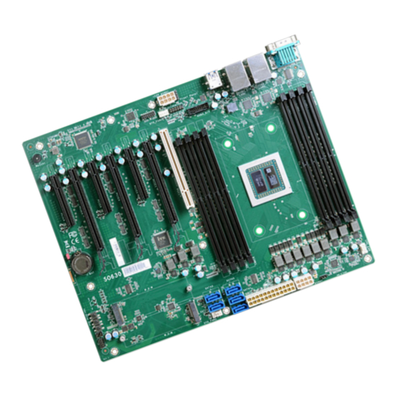
- Page 1 SO630 ATX Industrial Motherboard User’s Manual A-604-M-2045 ver.MP_MP_4-1521_15-14...
- Page 2 1. The changes or modifications not expressly approved by the party responsible for com- are the properties of the respective owners. pliance could void the user’s authority to operate the equipment. 2. Shielded interface cables must be used in order to comply with the emission limits. User's Manual | SO630...
-
Page 3: Table Of Contents
SATA Configuration .......................24 USB Configuration ......................25 PCI Express Configuration ....................26 Debug Configuration .....................27 UEFI Device Manager ....................27 SIO NCT6112D .......................28 Console Redirection ......................30 Security ..........................31 Boot ............................31 Exit ............................33 Updating the BIOS ........................33 Notice: BIOS SPI ROM......................33 User's Manual | SO630... - Page 4 • To reduce the risk of electric shock, unplug the power cord before removing the sys- tem chassis cover for installation or servicing. After installation or servicing, cover the system chassis before plugging the power cord. User's Manual | SO630...
- Page 5 Memory module • Storage device such as a hard disk drive. • Power supply External system peripherals may also be required for navigation and display, including at least a keyboard, a mouse and a video display monitor. User's Manual | SO630...
-
Page 6: Chapter 1 - Introduction
System Reset, Programmable via Software from 1 to 255 TIMER Interval Seconds SECURITY TPM2.0 (opt.) POWER Type ATX power input Consumption RTC Battery CR2032 Coin Cell OS SUPPORT Windows 10 Windows Server 2019 Linux ENVIRONMENT Temperature Operating: -5 to 65°C Storage: -40 to 85°C User's Manual | SO630... -
Page 7: Features
S3 (STR - Suspend To RAM) state. sible external Plug and Play peripherals. RTC Timer The Real Time Clock (RTC) installed on the system board allows your system to automatically power-on on the set date and time. User's Manual | SO630... -
Page 8: Block Diagram
SATA 3.0 PCIe x8 SATA 3.0 3x Switch PCIe x8 PCIe x2 SATA 3.0 2x ASM1062R PCIe x8 PCIe x16 PCIe x8 Switch PCIe x1 IT8893E PCIe x8 LPC Bus RS-232/422/485 1x Super IO RS-232 1x User's Manual | SO630... -
Page 9: Chapter 2 - Hardware Installation
If a wrist strap is unavailable, establish and maintain contact with the system chassis throughout any procedures requiring ESD protection. X LED and Switch EPYC Reset Button Power Button User's Manual | SO630... -
Page 10: System Memory
CH-A: DIMM 1, 2 CH-B: DIMM 3, 4 CH-C: DIMM 5, 6 CH-D: DIMM 7, 8 While only one DIMM is installed in a channel, it should be installed in even num- ber DIMM (DIMM 2/4/6/8). User's Manual | SO630... -
Page 11: Removing The Dimm Module
Hold the card by its edges and remove it from the slot. The tabs snap automatically to the edges of the card and lock the card in place. Step 1 Step 1 Step 2 Step 2 Step 3 Step 3 User's Manual | SO630... -
Page 12: Cpu
Align the 4 screw holes and tighten the heat sink up by inserting screws, DO remember to con- nect the fan cable on the board. There are 4 screw holes around the CPU for the heat sink to be mounted. User's Manual | SO630... -
Page 13: Jumper Settings
1 and pin 2. 3. Plug the power cord and power-on the system. USB 6 (USB 3.1 Gen1) USB 5 (USB 3.1 Gen1) „ 1-2 On: Normal (default) „ 2-3 On: Clear CMOS Data User's Manual | SO630... -
Page 14: Com (Serial) Ports
RXD+ pin-header connector for monitoring the BMC. RXD- Features • 2 x (10/100/1000Mbps) Note: The BMC COM port is used to monitor the IPMI, and may not be present when your model does not support IPMI. User's Manual | SO630... -
Page 15: Usb Ports
Plug and Play peripherals. The system board is equipped with mul- tiple USB ports as listed below: EPYC • 6 x USB 3.1 Gen 1 rear ports (USB 1/2/3/4/5/6) • 2 x USB 3.1 Gen 1 internal ports, box headers (USB 7/8) User's Manual | SO630... -
Page 16: Internal I/O Connectors
SATA 3 (P0) and SATA 4 (P1) support RAID. FRAME# VCC3 LAD3 LAD2 Features SERIRQ • 5 Serial ATA 3.0 ports with data transfer rate up to 6Gb/s 5VSB • Integrated Advanced Host Controller Interface (AHCI) controller • Support RAID 0, RAID 1, SPAN User's Manual | SO630... -
Page 17: Cooling Fan Connectors
Insufficient power supplied to the system may result in instability or malfunction of the add-in boards and peripherals. Calculating the system’s approximate power usage is important to ensure that the power supply meets the system’s consump- tion requirements. User's Manual | SO630... -
Page 18: Chassis Intrusion
Power On Suspend) state, it will blink at 1-second intervals. When the system is in the S3 (STR - Suspend To RAM) state, it will blink at 4-second intervals. Power Button This button is used to switch the system's power on or off . User's Manual | SO630... -
Page 19: Expansion Slots
The M.2 socket is the Next Generation Form Factor (NGFF) which is designed to support mul- tiple modules and make the M.2 more suitable in application for solid-state storage. Note: The PCIe x16 slot will automatically switch to x8 bandwidth when the paired PCIe x8 slot is in use. User's Manual | SO630... -
Page 20: Battery
The • Replace only with the same or equivalent type recommended by the manufacturer. card should be lying parallel to the board when it’s correctly • Dispose of used batteries according to local ordinances. mounted. User's Manual | SO630... -
Page 21: Chapter 3 - Bios Setup
“Press DEL to run setup” will appear on the screen. If the message that field and press <Enter>. disappears before you respond, restart the system or press the “Reset” button. You may also restart the system by pressing the <Ctrl> <Alt> and <Del> keys simultaneously. User's Manual | SO630... -
Page 22: Main
00 to 59. Second displays seconds from 00 to 59. System Date The date format is <month>, <date>, <year>. Month displays the month, from 01 to 12. Date displays the date, from 01 to 31. Year displays the year, from 2000 to 2099. User's Manual | SO630... -
Page 23: Acpi Configuration
[Wake up time] Exit ←/→ Select Item Enter Select SubMenu Save and Exit Configure the time of day the system will wake on RTC — [HH:MM:SS]. This field will only ap- pear when “Wake On RTC” is enabled. User's Manual | SO630... -
Page 24: Cpu Configuration
Please make sure that the OS operating on your system is optimized for SMT, or update to a version supports SMT. This field is only available with the CPU supported. User's Manual | SO630... -
Page 25: Sata Configuration
RAID This option allows the Serial ATA controller(s) to use UEFI, RAID, and Intel Rapid Storage Technology. SATA Port 0-2/Hot Plug Enable or disable each Serial ATA port and its hot plug function. M.2-M (CN2)/Hot Plug Enable or disable each Serial ATA port and its hot plug function. User's Manual | SO630... -
Page 26: Usb Configuration
Enable or disable the Serial ATA controller. This following fields will only be displayed when this Enabled Enable Legacy USB support. field is enabled. Disabled Keep USB devices available only for EFI applications. Raid OPROM Enable to OPROM for RAID management. User's Manual | SO630... -
Page 27: Pci Express Configuration
GT/s). Gen 3 is only available for the PCIE1 port. This field may not appear when the speed of the port is not configurable. Hot Plug Enable or disable hot plug function of the port. This field may not appear when the port does not support hot plug. User's Manual | SO630... -
Page 28: Debug Configuration
This debug function is only used for J1 internal UART EFI debug baud rate Enter the baud rate to output EFI debug message. The default is 115200. Note: Network Device will not be configurable in Device Manager if "Network Stack" is disabled in the "Boot" menu. User's Manual | SO630... -
Page 29: Sio Nct6112D
WDT. Input any value between 1 to 255 seconds. ▼ WDT = [Enable] Counter Set the timeout value of the WDT — 1-255 seconds. Case Open Alert Enable or disable case open alert. Clean Case Open Status Clean current case open status including alert. User's Manual | SO630... - Page 30 Enable or disable the system smart fan. When disabled, fan speed will not be controllable ac- cording to different system temperatures. Instead, a Fix Fan Speed Count field will be displayed to configure at which speed the fan will always be fixed regardless of system temperature. User's Manual | SO630...
-
Page 31: Console Redirection
Select data bits — 7 bits or 8 bits. Parity Select parity bits — none, even or odd. Stop Bits Select stop bits — 1 bit or 2 bits. Flow Control Select flow control type — none, RTS/CTS or XON/XOFF. User's Manual | SO630... -
Page 32: Security
This field is used to enable or disable network stacks, i.e. IPv4 or IPv6 network protocols. Note: The devices shown here are based on a carrier board that may not resemble your actual carrier board. The actual I/O devices depend entirely on those present on your actual carrier board. User's Manual | SO630... - Page 33 "Boot Type" is set to “Legacy Boot Type” or “Dual Boot Type”, and when "Network Stack" is enabled. USB Boot Enable or disable booting to USB boot devices. Quiet Boot Enable or disable booting in text mode. User's Manual | SO630...
-
Page 34: Exit
Select this option to save BIOS configuration settings to a USB flash device. Restore Setting from file This field will appear only when a USB flash device is detected. Select this field to restore setting from the USB flash device. User's Manual | SO630... -
Page 35: Table Of Contents Chapter 4 - Raid
Combination of RAID 0 (data striping) RAID 10 Stripe (not same mirror) and RAID 1 (mirroring) Extends capacity to the sum of total SPAN None drives, the second drive won't be used until the first one is full. User's Manual | SO630... - Page 36 3. Wait the process to start, the whole process takes about several seconds depends on Step 3: Create RAID 0/RAID 1/ SPAN the volume amounts. 1. Select the desired mode and press <Enter>. 4. "*" shown on bottom indicates the progress. 2. Press <Y> to confirm the process. User's Manual | SO630...
- Page 37 Chapter 4 RAID SETTINGS 5. Relevant information will appear with the message "Mode change is completed." on bot- tom. Other RAID modes follow the same procedure as well. User's Manual | SO630...
Need help?
Do you have a question about the SO630 and is the answer not in the manual?
Questions and answers