Table of Contents
Advertisement
Quick Links
CP2 40 0/ 1-DK
CP2400
C P 2 4 0 1 D
K
U
'
G
A N D
EVELOPMENT
IT
S E R
S
U I D E
1. Overview
The LCD Development Kits (CP2400-DK and CP2401-DK) provide all the hardware and software required to
develop and test LCD applications. The CP240x LCD Firmware Library is included to aid in the code development
process and handle the communication between the C8051F9xx MCU and the CP2400/1 LCD controller. The LCD
library can be used to communicate with the LCD controller through the SPI interface (CP2400-DK) or the SMBus
interface (CP2401-DK). Example code using the LCD library is included with both development kits.
The LCD development kit hardware includes a C8051F930 target board, CP2400 or CP2401 LCD Development
Board, USB Debug adapter, and an ac to dc power adapter. The C8051F930 Target Board features the 25 MIPS,
64 kB Flash, over 4 kB RAM, 8051-based C8051F930 MCU. The C8051F930 MCU is part of the low-power family
and can operate with a supply voltage from 0.9 to 3.6 V. The MCU LCD interface provided by the AB board
consists of the CP2400/1 LCD controller and an LCD and is compatible with the C8051F930-DK and C8051F912-
DK. The LCD development kit includes example code which uses either the SPI interface (CP2400-DK) or SMBus
interface (CP2401-DK) on the C8051F930 to control the LCD using the LCD library.
The Silicon Labs' IDE supports full-speed, non-intrusive MCU debugging and is bundled with an evaluation version
of the Keil C51 Toolchain allowing immediate application code evaluation in C. Projects with up to 4 kB of object
code and unlimited library code can be developed using the included toolset. Numerous application code examples
are included in the development kit and a walkthrough of an LCD example is included in 6. "Example Source
Code‚" on page 11.
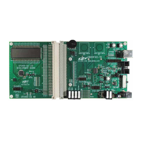
Figure 1. C8051F912-TB Target Board and CP2400 LCD Development Board
Rev. 0.1 10/09
Copyright © 2009 by Silicon Laboratories
CP2400/1-DK
Downloaded from
Elcodis.com
electronic components distributor
Advertisement
Table of Contents

Subscribe to Our Youtube Channel
Related Manuals for Silicon Laboratories CP2400-DK


Summary of Contents for Silicon Laboratories CP2400-DK
- Page 1 C8051F9xx MCU and the CP2400/1 LCD controller. The LCD library can be used to communicate with the LCD controller through the SPI interface (CP2400-DK) or the SMBus interface (CP2401-DK). Example code using the LCD library is included with both development kits.
-
Page 2: Kit Contents
CP2400 or CP2401 LCD development board CP240x development kit quick-start guide Silicon Laboratories IDE and product information CD-ROM. CD content includes the following: Silicon Laboratories Integrated Development Environment (IDE) Keil 8051 development tools (macro assembler, linker, evaluation C compiler) ... -
Page 3: Software Overview
CP210x USB to UART Virtual COM Port (VCP) drivers 3.1. Software Installation The included CD-ROM contains the Silicon Laboratories Integrated Development Environment (IDE), Keil software 8051 tools and additional documentation. Insert the CD-ROM into your PC’s CD-ROM drive. An installer will automatically launch, allowing you to install the IDE software or read documentation by clicking buttons on the Installation Panel. - Page 4 The Silicon Laboratories IDE integrates a source-code editor, a source-level debugger, and an in-system Flash programmer. See Section 5. "Using the Keil Software 8051 Tools with the Silicon Laboratories IDE‚" on page 10 for detailed information on how to use the IDE. The Keil Evaluation Toolset includes a compiler, linker, and assembler and easily integrates into the IDE.
-
Page 5: Configuration Wizard
CP2400/1-DK 3.5. Configuration Wizard 2 The Configuration Wizard 2 is a code generation tool for all of the Silicon Laboratories devices. Code is generated through the use of dialog boxes for each of the device's peripherals. Figure 4. Configuration Wizard 2 Utility The Configuration Wizard utility helps accelerate development by automatically generating initialization source code to configure and enable the on-chip resources needed by most design projects. - Page 6 CP2400/1-DK 3.6. Silicon Labs Battery Life Estimator The Battery Life Estimator is a system design tool for battery operated devices. It allows the user to select the type of battery they are using in the system and enter the supply current profile of their application. Using this information, it performs a simulation and provides an estimated system operating time.
- Page 7 CP2400/1-DK Figure 6. Battery Life Estimator Discharge Profile Editor The Discharge Profile Editor allows the user to modify the profile name and description. The four text entry boxes on the left hand side of the form allow the user to specify the amount of time the system spends in each power mode.
- Page 8 3.7. Keil µVision2 and µVision3 Silicon Laboratories Drivers As an alternative to the Silicon Laboratories IDE, the µVision debug driver allows the Keil µVision2 and µVision3 IDEs to communicate with Silicon Laboratories’ on-chip debug logic. In-system Flash memory programming integrated into the driver allows for rapid updating of target code.
-
Page 9: Hardware Setup Using A Usb Debug Adapter
CP2400/1-DK 4. Hardware Setup using a USB Debug Adapter The target board is connected to a PC running the Silicon Laboratories IDE via the USB Debug Adapter as shown in Figure 9. 1. Connect the LCD development board to the F930 target board as shown in Figure 8. -
Page 10: Using The Keil Software 8051 Tools With The Silicon Laboratories Ide
Keil 8051 tools with the Silicon Laboratories IDE. To build an absolute object file using the Silicon Laboratories IDE project manager, you must first create a project. A project consists of a set of files, IDE configuration, debug views, and a target build configuration (list of files and tool configurations used as input to the assembler, compiler, and linker when building an output object file). -
Page 11: Example Source Code
CP2400/1-DK 6. Example Source Code Example source code and register definition files are provided in the “SiLabs\MCU\Examples\C8051F93x_92x\” default directory during IDE installation. These files may be used as a template for code development. Example applications include a blinking LED example which configures the green LED on the target board to blink at a fixed rate. - Page 12 CP2400/1-DK If using a CP2400, this line should say: #define BUS_INTERFACE 6.4.3. Example Selection The example that is run on the CP2400/1 LCD development board can be selected in the file, app_config.h. The available examples include a voltage display example, digit display example, and several current measurement examples.
- Page 13 CP2400/1-DK 7. C8051F930 Target Board The CP2400/1 Development Kit includes a target board with a C8051F930 device pre-installed for evaluation and preliminary software development. Numerous input/output (I/O) connections are provided to facilitate prototyping using the target board. Refer to Figure 10 for the locations of the various I/O connectors. Figure 12 on page 15 shows the factory default shorting block positions.
- Page 14 CP2400/1-DK The following items are located on the bottom side of the board. See Figure 11. Battery Holder for 1.5 V AAA. Use for one-cell or two-cell mode. Battery Holder for 1.5 V AAA. Use for two-cell mode only. Battery Holder for 3 V Coin Cell (CR2032). Battery Holder for 1.5 V Button Cell (A76 or 357).
- Page 15 CP2400/1-DK 7.1. Target Board Shorting Blocks: Factory Defaults The C8051F930 target board comes from the factory with pre-installed shorting blocks on many headers. Figure 12 shows the positions of the factory default shorting blocks. P1.6 P0.2 P0.3 P1.5 P1.4 USB POWER TOUCH SENSE SWITCH TOUCH SENSE SWITCH P2.0...
- Page 16 CP2400/1-DK 7.2. Target Board Power Options and Current Measurement The C8051F930 Target Board supports three power options, selectable by the three-way header (J10/J11). The power options vary based on the configuration (one-cell or two-cell mode) selected by SW4. Power to the MCU may be switched on/off using the power switch (SW5).
-
Page 17: Switches And Leds
CP2400/1-DK 7.2.4. Measuring Current The header (J17) and terminal block (H2) provide a way to measure the total supply current flowing from the power supply source to the MCU. The measured current does not include any current from the VBAT LED (DS2), the address latch (U4) or the quiescent current from the power supply;... - Page 18 CP2400/1-DK Table 1. Target Board I/O Descriptions Description Header(s) Reset none P0.2 J8[5–6] P0.3 J8[7–8] P2.0 (Touch Sense Switch) P2.0 none P2.1 (Touch Sense Switch) P2.1 none Red LED (P1.5) P1.5 J8[1–2] Yellow LED (P1.6) P1.6 J8[3–4] Red LED (VDD/DC+) VDD/DC+ Supply Net Red LED (VBAT) VBAT Supply Net...
- Page 19 CP2400/1-DK Table 2. P1 Pin Descriptions (Continued) Row A Row B Row C Description Description Description Pin # Pin # Pin # P2.3/A11 P2.2/A10 P2.1/A9 P2.0/A8 P0.2H P2.3/A11 P2.2/A10 P2.1/A9 P2.0/A8 VDD/DC+ VBAT 7.7. Target Board DEBUG Interface (J9) The DEBUG connector J9 provides access to the DEBUG (C2) pins of the C8051F930. It is used to connect the Serial Adapter or the USB Debug Adapter to the target board for in-circuit debugging and Flash programming.
- Page 20 CP2400/1-DK Table 4. Serial Interface Header (J12) Description Header Pins UART0 Pin Description J12[9–10] CP2103_VIO (VDD/DC+) J12[7–8] TX_MCU (P0.5) J12[5–6] RX_MCU (P0.4) J12[3–4] RTS (P0.6) J12[1–2] CTS (P0.7) 7.9. Analog I/O (H1) Several of the C8051F930 target device’s port pins are connected to the H1 terminal block. Refer to Table 5 for the H1 terminal block connections.
- Page 21 CP2400/1-DK 8. CP2400/1 AB LCD Development Board The CP2400 and CP2401 Development Kits include a CP2400 or CP2401 LCD Development Board designed to connect to C8051F9xx target boards. Various input/output (I/O) connectors are provided to facilitate prototyping using the development board. Refer to Figure 13 for the locations of the various I/O connectors. Figure 14 on page 22 shows the factory default shorting block positions.
- Page 22 CP2400/1-DK 8.1. Target Board Shorting Blocks: Factory Defaults The CP2400/1 target board comes from the factory with pre-installed shorting blocks on many headers. Figure 14 shows the positions of the factory default shorting blocks. CP2400-GQ LCD DEVELOPMENT BOARD CP2400 IMEASURE SILICON LABS J5J4 www.silabs.com...
- Page 23 CP2400/1-DK 8.2. AB Board Current Measurement The header (J2) provides a way to measure the total supply current flowing from the power supply source to the CP2400/1. The measured current does not include any current from the LED (D1) or the Power LED (D2). See the target board schematics in Figures 15 through 18 for additional information.
- Page 24 CP2400/1-DK 8.6. Expansion I/O Connector (P1) The 96-pin Expansion I/O connector P1 provides access to all signal pins of the CP2400/1 device. In addition, power supply and ground pins are included. A small through-hole prototyping area is also provided. See Table 8 for a list of pin descriptions for P1.
- Page 25 CP2400/1-DK 9. Schematics Rev. 0.1 Downloaded from Elcodis.com electronic components distributor...
- Page 26 CP2400/1-DK Rev. 0.1 Downloaded from Elcodis.com electronic components distributor...
- Page 27 CP2400/1-DK Rev. 0.1 Downloaded from Elcodis.com electronic components distributor...
- Page 28 CP2400/1-DK Rev. 0.1 Downloaded from Elcodis.com electronic components distributor...
- Page 29 CP2400/1-DK Rev. 0.1 Downloaded from Elcodis.com electronic components distributor...
- Page 30 CP2400/1-DK Rev. 0.1 Downloaded from Elcodis.com electronic components distributor...
- Page 31 CP2400/1-DK Rev. 0.1 Downloaded from Elcodis.com electronic components distributor...
-
Page 32: Contact Information
Silicon Laboratories products are not designed, intended, or authorized for use in applications intended to support or sustain life, or for any other application in which the failure of the Silicon Laboratories product could create a situation where per- sonal injury or death may occur.
Need help?
Do you have a question about the CP2400-DK and is the answer not in the manual?
Questions and answers