LOVATO ELECTRIC DMG900 Instruction Manual
Digital power analyzer - power transducer
Hide thumbs
Also See for DMG900:
- Installation manual (23 pages) ,
- Instruction manual (35 pages) ,
- Installation manual (22 pages)
Table of Contents
Advertisement
Available languages
Available languages
Quick Links
LOVATO ELECTRIC S.P.A.
24020 GORLE (BERGAMO) ITALIA
VIA DON E. MAZZA, 12
TEL. 035 4282111
FAX (Nazionale): 035 4282200
FAX (International): +39 035 4282400
L
E
E-mail info@
ovato
lectric.com
L
E
Web
www.
ovato
lectric.com
WARNING!
- Carefully read the manual before the installation or use.
- This equipment is to be installed by qualified personnel, complying with current standards, to avoid damages or safety hazards.
- Before any maintenance operation on the device, remove all the voltages from supply and measuring inputs and short-circuit the CT input terminals.
- The manufacturer cannot be held responsible for electrical safety in case of improper use of the equipment.
- Products illustrated herein are subject to alteration and changes without prior notice. Technical data and descriptions in the documentation are accurate, to the
best of our knowledge, but no liabilities for errors, omissions or contingencies arising therefrom are accepted.
- A circuit breaker must be included in the electrical installation of the building. It must be installed close by the equipment and within easy reach of the operator.
It must be marked as the disconnecting device of the equipment: IEC /EN 61010-1 § 6.11.2.
- Clean the instrument with a soft dry cloth; do not use abrasives, liquid detergents or solvents.
INDEX
Introduction . . . . . . . . . . . . . . . . . . . . . . . . . . . . . . . . . . . . . . . . . . . . . . . . . . . . . . . . . . . . . . . . . . . . . . . . . . . . . . . . . . . . . . . . . . . . . . . . . . . . . . . . . . . . . . . . .
Description . . . . . . . . . . . . . . . . . . . . . . . . . . . . . . . . . . . . . . . . . . . . . . . . . . . . . . . . . . . . . . . . . . . . . . . . . . . . . . . . . . . . . . . . . . . . . . . . . . . . . . . . . . . . . . . . .
Touch screen functions . . . . . . . . . . . . . . . . . . . . . . . . . . . . . . . . . . . . . . . . . . . . . . . . . . . . . . . . . . . . . . . . . . . . . . . . . . . . . . . . . . . . . . . . . . . . . . . . . . . . . . . .
Neutral measurement . . . . . . . . . . . . . . . . . . . . . . . . . . . . . . . . . . . . . . . . . . . . . . . . . . . . . . . . . . . . . . . . . . . . . . . . . . . . . . . . . . . . . . . . . . . . . . . . . . . . . . . . .
Measurement viewing . . . . . . . . . . . . . . . . . . . . . . . . . . . . . . . . . . . . . . . . . . . . . . . . . . . . . . . . . . . . . . . . . . . . . . . . . . . . . . . . . . . . . . . . . . . . . . . . . . . . . . . . .
Main menu . . . . . . . . . . . . . . . . . . . . . . . . . . . . . . . . . . . . . . . . . . . . . . . . . . . . . . . . . . . . . . . . . . . . . . . . . . . . . . . . . . . . . . . . . . . . . . . . . . . . . . . . . . . . . . . . .
Table of display pages . . . . . . . . . . . . . . . . . . . . . . . . . . . . . . . . . . . . . . . . . . . . . . . . . . . . . . . . . . . . . . . . . . . . . . . . . . . . . . . . . . . . . . . . . . . . . . . . . . . . . . . . .
Harmonic analysis page . . . . . . . . . . . . . . . . . . . . . . . . . . . . . . . . . . . . . . . . . . . . . . . . . . . . . . . . . . . . . . . . . . . . . . . . . . . . . . . . . . . . . . . . . . . . . . . . . . . . . . . .
Waveform page . . . . . . . . . . . . . . . . . . . . . . . . . . . . . . . . . . . . . . . . . . . . . . . . . . . . . . . . . . . . . . . . . . . . . . . . . . . . . . . . . . . . . . . . . . . . . . . . . . . . . . . . . . . . . .
Energy meters page . . . . . . . . . . . . . . . . . . . . . . . . . . . . . . . . . . . . . . . . . . . . . . . . . . . . . . . . . . . . . . . . . . . . . . . . . . . . . . . . . . . . . . . . . . . . . . . . . . . . . . . . . . .
Hour counters page . . . . . . . . . . . . . . . . . . . . . . . . . . . . . . . . . . . . . . . . . . . . . . . . . . . . . . . . . . . . . . . . . . . . . . . . . . . . . . . . . . . . . . . . . . . . . . . . . . . . . . . . . . .
Trend graph page . . . . . . . . . . . . . . . . . . . . . . . . . . . . . . . . . . . . . . . . . . . . . . . . . . . . . . . . . . . . . . . . . . . . . . . . . . . . . . . . . . . . . . . . . . . . . . . . . . . . . . . . . . . . .
Counters page . . . . . . . . . . . . . . . . . . . . . . . . . . . . . . . . . . . . . . . . . . . . . . . . . . . . . . . . . . . . . . . . . . . . . . . . . . . . . . . . . . . . . . . . . . . . . . . . . . . . . . . . . . . . . . .
User pages . . . . . . . . . . . . . . . . . . . . . . . . . . . . . . . . . . . . . . . . . . . . . . . . . . . . . . . . . . . . . . . . . . . . . . . . . . . . . . . . . . . . . . . . . . . . . . . . . . . . . . . . . . . . . . . . .
Time and date . . . . . . . . . . . . . . . . . . . . . . . . . . . . . . . . . . . . . . . . . . . . . . . . . . . . . . . . . . . . . . . . . . . . . . . . . . . . . . . . . . . . . . . . . . . . . . . . . . . . . . . . . . . . . . .
Password access . . . . . . . . . . . . . . . . . . . . . . . . . . . . . . . . . . . . . . . . . . . . . . . . . . . . . . . . . . . . . . . . . . . . . . . . . . . . . . . . . . . . . . . . . . . . . . . . . . . . . . . . . . . . .
Settings lock . . . . . . . . . . . . . . . . . . . . . . . . . . . . . . . . . . . . . . . . . . . . . . . . . . . . . . . . . . . . . . . . . . . . . . . . . . . . . . . . . . . . . . . . . . . . . . . . . . . . . . . . . . . . . . . .
Expandability . . . . . . . . . . . . . . . . . . . . . . . . . . . . . . . . . . . . . . . . . . . . . . . . . . . . . . . . . . . . . . . . . . . . . . . . . . . . . . . . . . . . . . . . . . . . . . . . . . . . . . . . . . . . . . . .
Additional resources . . . . . . . . . . . . . . . . . . . . . . . . . . . . . . . . . . . . . . . . . . . . . . . . . . . . . . . . . . . . . . . . . . . . . . . . . . . . . . . . . . . . . . . . . . . . . . . . . . . . . . . . . .
Communication channels . . . . . . . . . . . . . . . . . . . . . . . . . . . . . . . . . . . . . . . . . . . . . . . . . . . . . . . . . . . . . . . . . . . . . . . . . . . . . . . . . . . . . . . . . . . . . . . . . . . . . .
Inputs, outputs, internal variables, counters . . . . . . . . . . . . . . . . . . . . . . . . . . . . . . . . . . . . . . . . . . . . . . . . . . . . . . . . . . . . . . . . . . . . . . . . . . . . . . . . . . . . . . . .
Limit thresholds . . . . . . . . . . . . . . . . . . . . . . . . . . . . . . . . . . . . . . . . . . . . . . . . . . . . . . . . . . . . . . . . . . . . . . . . . . . . . . . . . . . . . . . . . . . . . . . . . . . . . . . . . . . . .
Boolean logic . . . . . . . . . . . . . . . . . . . . . . . . . . . . . . . . . . . . . . . . . . . . . . . . . . . . . . . . . . . . . . . . . . . . . . . . . . . . . . . . . . . . . . . . . . . . . . . . . . . . . . . . . . . . . . . .
Remote-controlled variables . . . . . . . . . . . . . . . . . . . . . . . . . . . . . . . . . . . . . . . . . . . . . . . . . . . . . . . . . . . . . . . . . . . . . . . . . . . . . . . . . . . . . . . . . . . . . . . . . . . .
Alarms . . . . . . . . . . . . . . . . . . . . . . . . . . . . . . . . . . . . . . . . . . . . . . . . . . . . . . . . . . . . . . . . . . . . . . . . . . . . . . . . . . . . . . . . . . . . . . . . . . . . . . . . . . . . . . . . . . . . .
Event log . . . . . . . . . . . . . . . . . . . . . . . . . . . . . . . . . . . . . . . . . . . . . . . . . . . . . . . . . . . . . . . . . . . . . . . . . . . . . . . . . . . . . . . . . . . . . . . . . . . . . . . . . . . . . . . . . . .
Tariffs . . . . . . . . . . . . . . . . . . . . . . . . . . . . . . . . . . . . . . . . . . . . . . . . . . . . . . . . . . . . . . . . . . . . . . . . . . . . . . . . . . . . . . . . . . . . . . . . . . . . . . . . . . . . . . . . . . . . .
Monthly energy counters . . . . . . . . . . . . . . . . . . . . . . . . . . . . . . . . . . . . . . . . . . . . . . . . . . . . . . . . . . . . . . . . . . . . . . . . . . . . . . . . . . . . . . . . . . . . . . . . . . . . . . .
Data logger function . . . . . . . . . . . . . . . . . . . . . . . . . . . . . . . . . . . . . . . . . . . . . . . . . . . . . . . . . . . . . . . . . . . . . . . . . . . . . . . . . . . . . . . . . . . . . . . . . . . . . . . . . .
Energy quality analysis . . . . . . . . . . . . . . . . . . . . . . . . . . . . . . . . . . . . . . . . . . . . . . . . . . . . . . . . . . . . . . . . . . . . . . . . . . . . . . . . . . . . . . . . . . . . . . . . . . . . . . . .
Selection of interface type (DMG900T) . . . . . . . . . . . . . . . . . . . . . . . . . . . . . . . . . . . . . . . . . . . . . . . . . . . . . . . . . . . . . . . . . . . . . . . . . . . . . . . . . . . . . . . . . . . .
Setting of parameters (set-up) . . . . . . . . . . . . . . . . . . . . . . . . . . . . . . . . . . . . . . . . . . . . . . . . . . . . . . . . . . . . . . . . . . . . . . . . . . . . . . . . . . . . . . . . . . . . . . . . . .
Table of parameters . . . . . . . . . . . . . . . . . . . . . . . . . . . . . . . . . . . . . . . . . . . . . . . . . . . . . . . . . . . . . . . . . . . . . . . . . . . . . . . . . . . . . . . . . . . . . . . . . . . . . . . . . . .
Commands menu . . . . . . . . . . . . . . . . . . . . . . . . . . . . . . . . . . . . . . . . . . . . . . . . . . . . . . . . . . . . . . . . . . . . . . . . . . . . . . . . . . . . . . . . . . . . . . . . . . . . . . . . . . . .
Wiring test . . . . . . . . . . . . . . . . . . . . . . . . . . . . . . . . . . . . . . . . . . . . . . . . . . . . . . . . . . . . . . . . . . . . . . . . . . . . . . . . . . . . . . . . . . . . . . . . . . . . . . . . . . . . . . . . . .
Technical characteristics . . . . . . . . . . . . . . . . . . . . . . . . . . . . . . . . . . . . . . . . . . . . . . . . . . . . . . . . . . . . . . . . . . . . . . . . . . . . . . . . . . . . . . . . . . . . . . . . . . . . . . .
Installation . . . . . . . . . . . . . . . . . . . . . . . . . . . . . . . . . . . . . . . . . . . . . . . . . . . . . . . . . . . . . . . . . . . . . . . . . . . . . . . . . . . . . . . . . . . . . . . . . . . . . . . . . . . . . . . . . .
Wiring diagrams . . . . . . . . . . . . . . . . . . . . . . . . . . . . . . . . . . . . . . . . . . . . . . . . . . . . . . . . . . . . . . . . . . . . . . . . . . . . . . . . . . . . . . . . . . . . . . . . . . . . . . . . . . . . .
Terminal arrangement . . . . . . . . . . . . . . . . . . . . . . . . . . . . . . . . . . . . . . . . . . . . . . . . . . . . . . . . . . . . . . . . . . . . . . . . . . . . . . . . . . . . . . . . . . . . . . . . . . . . . . . . .
Mechanical dimensions . . . . . . . . . . . . . . . . . . . . . . . . . . . . . . . . . . . . . . . . . . . . . . . . . . . . . . . . . . . . . . . . . . . . . . . . . . . . . . . . . . . . . . . . . . . . . . . . . . . . . . . .
INTRODUCTION
DMG900 - The DMG900 power analyzer has been designed to combine the maximum possible easiness of operation together with a wide choice of advanced
functions. Thanks to its flush-mount 96x96mm housing, the DMG900 joins the modern design of the front panel with the tool-less mounting of the device body
and the expansion capability of the rear panel, where it is possible to mount plug-in modules of EXP... series. The graphic, touch-screen LCD display offers a
user-friendly interface. The rich variety of functions, makes the DMG series multimeters the ideal choice for a wide range of applications.
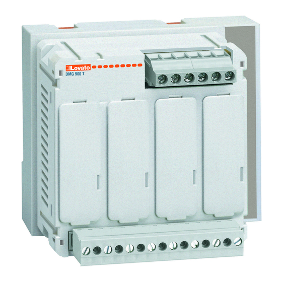
DMG900T - The DMG900T is the Transducer version of the DMG900, for DIN-rail mount. This device has the same characteristics as the DMG900, but has no
display and touch screen. Instead of the integrated display, the DMG900T has an interface board that consent the connection in one of the following modes:
- RS232 communication port
- RS485 communication port
- Remote display communication port for DMG900RD
NOTE: When not differently specified, all the characteristics reported in the following part of the manual are referred to both models. In particular, every detail that
is in relation with the display and the touch screen can be referred to the DMG900T used in combination with the remote display unit DMG900RD.
GB
Digital power analyzer - Power transducer
Instructions manual
DMG900 - DMG900T
G
B
Page
1
2
2
2
2
3
4
5
5
5
5
6
6
6
6
7
7
8
9
9
9
10
10
10
10
11
11
12
12
12
13
14
15
21
21
22
23
24
25
25
1
Advertisement
Chapters
Table of Contents

Subscribe to Our Youtube Channel
Related Manuals for LOVATO ELECTRIC DMG900


Summary of Contents for LOVATO ELECTRIC DMG900
-
Page 1: Table Of Contents
The rich variety of functions, makes the DMG series multimeters the ideal choice for a wide range of applications. DMG900T - The DMG900T is the Transducer version of the DMG900, for DIN-rail mount. This device has the same characteristics as the DMG900, but has no display and touch screen. -
Page 2: Description
DESCRIPTION DMG900: – Flush-mount housing, 96x96mm – Graphic LCD display, 128x112 pixels, white backlight, 4 grey levels. – Navigation and setting through touch screen. – Built-in buzzer. DMG900T: – Power transducer – Version for panel interior, DIN-rail mount – Selectable interface: RS232 or RS485 or Remote display Common characteristics: –... -
Page 3: Main Menu
– In each measurement page, there is a part of the display composed by two rows, that the user can use to show auxiliary information, selecting among: • Alphanumeric description of the plant, the distribution panel or section monitored by the DMG900. -
Page 4: Table Of Display Pages
TABLE OF DISPLAY PAGES Selection with ⬅ and ➡ Selection with icons N° PAGES SUB-PAGES VOLTAGE - CURRENT - V(L1-L2), V(L2-L3), V(L3-L1), I(L1), I(L2), I(L3) PHASE-TO-PHASE VOLTAGES - V(L1-L2), V(L2-L3), V(L3-L1), V(LL)EQV PHASE-TO-NEUTRAL VOLTAGES - V(L1-N), V(L2-N), V(L3-N), V(L-N)EQV PHASE AND NEUTRAL CURRENTS - I(L1), I(L2), I(L3), I(N) calculated ACTIVE POWER - P(L1), P(L2), P(L3), P(TOT) REACTIVE POWER - Q(L1), Q(L2), Q(L3), Q(TOT) APPARENT POWER - S(L1), S(L2), S(L3), S(TOT) -
Page 5: Harmonic Analysis Page
HARMONIC ANALYSIS PAGE – The DMG900 provides the harmonic analysis up to the 63rd order (7th order if frequency = 400Hz) of the following measurements: • phase-to-phase voltages • phase-to-neutral voltages • phase and neutral currents – For each of these measurements, there is a display page that graphically represents the harmonic content (spectrum) through a bar graph. -
Page 6: Trend Graph Page
2 weeks. – If instead no EXP module with RTC is available , then the DMG900 operates with a virtual RTC that does not update when the auxiliary power is off. – In this case, a dedicated parameter allows to move automatically to the time-date setting page every time the device has been powered off and on, in order to remind the user to verify 7 set the correct time and date. -
Page 7: Password Access
SETTINGS LOCK – On the DMG900 there are two DIP-switches that are used to lock the access to parameter settings and / or to reset operations (commands menu). – This DIP switches are placed in a way that they become inaccessible once the sealable terminal cover is mounted. -
Page 8: Expandability
– When a DMG900 is powered on, it automatically recognises the EXP modules that have been mounted. – For the DMG900T, when it is not connected to a remote display DMG900RD, to recognize the expansion modules it is necessary to put the DIP switches in the correct position (see details on page 19). -
Page 9: Additional Resources
– The two channels can communicate at the same time. – Activating the Gateway function it is possible to use a DMG900 with both an Ethernet port and a RS485 port, that acts as a bridge over other DMGs equipped with RS-485 only, in order to achieve a more economic configuration (only one Ethernet port). -
Page 10: Limit Thresholds
– Example: using a remote variable (REMx) as a source for an output (OUTx), it will be possible to freely energise or de-energise one relay through the supervision software. This allows to use the DMG900 relays to drive lighting or similar loads. -
Page 11: Event Log
EVENT LOG – The DMG900 can store a list of events, that can be useful to the user in order to detect anomalies and/or keep track of the plant behaviour. – Every Eventi s stored with a sequential number and relative time stamp. -
Page 12: Monthly Energy Counters
EN 50160 standard prescriptions. – In particular, the DMG900 coupled with the EXP10 31 module allows to control the following phenomenon, each identified by a reference code: • Small variations of integrated average voltage (VLO – VHI) •... -
Page 13: Selection Of Interface Type (Dmg900T)
– Ultimately, there are analog counters in addition to those mentioned above, which also record the “slow” phenomenon but with large variations (NHI and NLO for voltage and frequency). These events should never take place and, for this reason, the N (never) reference is used. –... -
Page 14: Setting Of Parameters (Set-Up)
– When selecting the Remote Display position, the DMG900T is preset to control the DMG900RD, connected by a dedicated cable with RJ45 8-pole plugs. – When the RS-232 or RS-485 port are selected, the transmission format, the protocol and other properties of the communication channel can be selected from the communication menu COM1 (see set-up programming chapter). -
Page 15: Table Of Parameters
P01.07 – Set this parameter according to the used wiring diagram. See witring diagrams on last pages of the manual. P01.08 – Rated frequency of the line. With Aut setting, the DMG900 selects automatically between 50 and 60 Hz. If an energy quality module EXP10 31 is used or... - Page 16 P02.08 – Sub-page type to which the display returns after P02.06 has elapsed. P02.10 – Alphanumeric description of the plant or sub-section monitored by DMG900, that can be shown in the auxiliary window. P02.11 – P02.12 – Define the content of the two rows of the auxiliary window. It is possible to select among plant description, date and hour, energy counters etc.
- Page 17 M06 - TREND GRAPH Default Range P06.01 Trend graph measure kW (tot) VL-L (eq) AVG kW (tot) AVG kvar (tot) AVG kVA (tot) AVG P06.02 Autorange OFF-ON P06.03 Full scale value 1000 0-1000 P06.04 Full scale multiplier x1 - x1k - x1M P06.01 –...
- Page 18 M09 - ALARMS (ALAn, n=1..16) Default Range P09.n.01 Alarm source OFF-LIMx-INPx-BOOx P09.n.02 Channel number (x) 1-16 P09.n.03 Latch OFF-ON P09.n.04 Priority Low-High P09.n.05 Text ALAn (Text - 16 char) Note: this menu is divided into 16 sections, for alarms ALA1..16 P09.n.01 –...
- Page 19 M13 - INPUTS (INPn, n=1..16) Default Range P13.n.01 Input function OFF – ON – LOCK -SYNC- TAR–A – TAR-B – TAR-C – C01…C09 P13.n.02 Normal status OFF-ON P13.n.03 ON delay 0.05 0.00 - 600.00 P13.n.04 OFF delay 0.05 0.00 - 600.00 Note: this menu is divided into 16 sections, for digital inputs INP1..16 P13.n.01 = Input function: OFF –...
- Page 20 M17 - ANALOG OUTPUTS (AOUn, n=1..8) Default Range P17.n.01 Output type 0..20mA 4….20mA 0…10V -5V…+5V P17.n.02 Reference measure OFF- (measures) P17.n.03 Start of scale value -9999 - +9999 P17.n.04 Multiplier /100 – x10k P17.n.05 Full scale value -9999 - +9999 P17.n.06 Multiplier /100 –...
-
Page 21: Commands Menu
COMMANDS MENU – The commands menu allows executing some occasional operations like reading peaks resetting, counters clearing, alarms reset, etc. – If the Advanced level password has been entered, then the commands menu allows executing the automatic operations useful for the device configuration. –... -
Page 22: Technical Characteristics
TECHNICAL CHARACTERISTICS Auxiliary supply Insulation Rated voltage Us ‚ 100 - 440V Rated insulation voltage Ui 690V 110 - 250V Rated impulse withstand voltage Uimp 9.5kV Operating voltage range 90 - 484V Power frequency withstand voltage 5.2kV 93.5 - 300V Auxiliary supply and voltage input connections Frequency 45 - 66Hz... -
Page 23: Installation
– The locking of the terminal covers must be done inserting the proper wire in the side loops and applying the seal. DMG900T INSTALLATION – The DMG900T is designed for on 35mm DIN rail (EN60715) or by screws using extractible clips. – For electrical wiring and terminal cover installation, please see previous chapter referred to DMG900. -
Page 24: Wiring Diagrams
WIRING DIAGRAMS 3-phase connection whit or without neutral, V4 and neutral current 2-phase connection whit or without V4 and neutral current P01.07 = L1-L2-L3-N L1-L2-L3 P01.07 = L1-N-L2 100...440VAC 100...440VAC 110...250VDC 110...250VDC 12...48VDC 12...48VDC - -- V2 V3 -- - S1 S2 AUX SUPPLY VOLTAGE... -
Page 25: Terminal Arrangement
DMG900 TERMINALS POSITION A1/- A2/+ DMG900 MECHANICAL DIMENSIONS (mm) - Page 26 DMG900T COMMUNICATION PORTS WIRING DIAGRAMS Connection with remote Display RS232 RJ45 standard cable 3mt MAX DATA RS485 DISPLAY A1/- A2/+ Connection with PC RS232 DATA RS485 RS232 51C2 cable DISPLAY A1/- A2/+ RS485 connection B SG RS485 RS485 DMG900T n°31 DMG900T n°1 Repeat this wiring diagram up to 255 devices...
- Page 27 DMG900T TERMINALS POSITION RS232 DATA RS485 DISPLAY A1/- A2/+ DMG900T MECHANICAL DIMENSIONS (mm) 84.7 19.8 54.2...
-
Page 28: Introduzione
La ricca dotazione di funzioni fa dei multimetri serie DMG la soluzione ideale per un campo di applicazioni molto ampio. DMG900T - Il DMG900T è la versione Trasduttore del DMG900 per montaggio da interno quadro su guida DIN. Si tratta di un apparecchio che ha tutte le caratteristiche funzionali del DMG900, ma è... -
Page 29: Descrizione
DESCRIZIONE DMG900: – Esecuzione da incasso 96x96mm. – Display LCD grafico 128x112 pixel, retroilluminato, 4 livelli di grigio. – Navigazione ed impostazione tramite touch screen. – Buzzer integrato. DMG900T: – Trasduttore di potenza – Esecuzione da interno quadro per montaggio su guida DIN –... -
Page 30: Menu Principale
– In ciascuna finestra di misura è disponibile una parte del display con due righe, su ciascuna delle quali l’utente può scegliere di visualizzare alcune informazioni ausiliarie scegliendo fra: • Descrizione alfanumerica dell’impianto, del quadro di distribuzione o della sezione monitorata dal DMG900 • Ora e data correnti •... -
Page 31: Tabella Delle Pagine Del Display
TABELLA DELLE PAGINE DEL DISPLAY Selezione con ⬅ e ➡ Selezione con icone N° PAGINE SOTTO-PAGINE TENSIONI - CORRENTI - V(L1-L2), V(L2-L3), V(L3-L1), I(L1), I(L2), I(L3) TENSIONI CONCATENATE - V(L1-L2), V(L2-L3), V(L3-L1), V(LL)EQV TENSIONI DI FASE - V(L1-N), V(L2-N), V(L3-N), V(L-N)EQV CORRENTI DI FASE E DI NEUTRO - I(L1), I(L2), I(L3), I(N) calcolata POTENZA ATTIVA - P(L1), P(L2), P(L3), P(TOT) POTENZA REATTIVA - Q(L1), Q(L2), Q(L3), Q(TOT) -
Page 32: Pagina Analisi Armonica
PAGINA ANALISI ARMONICA – Nel DMG900 è disponibile l’analisi armonica fino al 63.mo ordine (7.mo ordine se frequenza = 400Hz) delle seguenti misure: • tensioni concatenate • tensioni di fase • correnti di fase e di neutro – Per ognuna di queste misure è disponibile una pagina che rappresenta graficamente il contenuto armonico (spettro) tramite un istogramma a barre. -
Page 33: Pagina Grafico Trend
– Il DMG900 gestisce un orologio datario che viene utilizzato per la memorizzazione degli eventi e per le funzioni legate al tempo. – Se il DMG900 è equipaggiato con un modulo di espansione dotato di orologio datario RTC (EXP10 30 o EXP 10 31), la data e l’ora vengono mantenuti anche senza presenza di alimentazione ausiliaria, per un tempo max di circa 2 settimane. -
Page 34: Accesso Tramite Password
BLOCCO IMPOSTAZIONI – Sul DMG900 sono disponibili due dip-switch che consentono di bloccare l’accesso alle impostazioni e alle operazioni di reset (menu comandi). – Questi dip switch sono posizionati in modo da diventare inaccessibili una volta montati i coprimorsetti piombabili. -
Page 35: Espandibilità
ESPANDIBILITÀ – Grazie al suo bus di espansione, il DMG900 può essere espanso con dei moduli aggiuntivi della serie EXP…. – E’ possibile collegare un massimo di 4 moduli EXP…. – I moduli EXP… supportati dal DMG900 si dividono nelle seguenti categorie: •... -
Page 36: Risorse Aggiuntive
– I canali di comunicazione possono funzionare contemporaneamente. – Attivando la funzione Gateway, è possibile avere un DMG900 equipaggiato con una porta Ethernet ed una porta RS485, che fa da ‘ponte’ verso altri DMG dotati della sola porta RS-485, in modo da ottenere un risparmio (1 solo punto di accesso Ethernet). -
Page 37: Soglie Limite
– Esempio: usando una variabile remota (REMx) come sorgente di una uscita (OUTx) sarà possibile attivare e disattivare liberamente un relè tramite il software di supervisione. Questo consentirebbe di utilizzare i relè di uscita del DMG900 per comandare dei carichi ad esempio illuminazione o altro. -
Page 38: Lista Eventi
LISTA EVENTI – Il DMG900 può tenere memorizzata una lista di eventi, che può essere utile all’utente per risalire alla causa di anomalie e/o per tenere traccia del comportamento dell’impianto. – Ciascun evento viene memorizzato con un numero sequenziale e con data e ora. -
Page 39: Conteggio Mensile Energie
EN 50160. – In particolare, il DMG900 in abbinamento al modulo EXP 10 31 permette di controllare le seguenti anomalie, ciascuna identificata da una sigla: • Variazioni di bassa entità della tensione media integrata (VLO – VHI) •... -
Page 40: Selezione Tipo Di Interfaccia (Dmg900T)
– Esistono infine dei contatori analoghi a quelli del punto precedente anche per i fenomeni ‘lenti’ ma di forte entità (NHI e NLO per tensione e frequenza). Questi eventi non dovrebbero mai manifestarsi, da qui la definizione N (never). – Quando si abilita la funzione di controllo della qualità dell’energia, l’intervallo di integrazione della tensione diviene automaticamente in modalità fissa di durata 10 minuti, mentre quello della frequenza diviene di 10 secondi. -
Page 41: Impostazione Dei Parametri (Set-Up)
– Quando viene selezionata la posizione Display remoto, il DMG900T si predispone per il controllo del DMG900RD, collegato tramite apposito cavo con spina RJ45 a 8 poli. – Quando vengono selezionate le porte RS-232 o RS-485, il formato di trasmissione, il protocollo e le altre proprietà del canale di trasmissione si selezionano tramite il menu comunicazione COM1 (vedere capitolo impostazioni di set-up). -
Page 42: Tabella Dei Parametri
P01.07 – Impostare concordemente allo schema di collegamento utilizzato. Vedere Schemi di collegamento alla fine del manuale. P01.08 – Frequenza nominale della linea. Con impostazione su Aut , il DMG900 sceglie automaticamente fra 50 e 60Hz. Se si utilizza il modulo per la qualità... - Page 43 P02.08 – Tipo di sotto-pagina alla quale il display torna dopo trascorso P02.06. P02.10 – Descrizione alfanumerica dell’impianto o sottosezione servita dal DMG900, che può essere visualizzata nella finestra ausiliaria. P02.11 - P02.12 - Definiscono il contenuto delle due righe della finestra ausiliaria. Si può selezionare fra la descrizione dell’impianto, data e ora, contatori di energia ecc.
- Page 44 M06 - GRAFICO TREND Default Range P06.01 Misura per pagina trend kW (tot) VL-L (eq) AVG kW (tot) AVG kvar (tot) AVG kVA (tot) AVG P06.02 Autorange scala OFF-ON P06.03 Valore fondo scala 1000 0-1000 P06.04 Moltiplicatore fondo scala x1 - x1k - x1M P06.01 –...
- Page 45 M09 - ALLARMI (ALAn, n=1..16) Default Range P09.n.01 Sorgente allarme OFF-LIMx-INPx-BOOx P09.n.02 Numero canale (x) 1-16 P09.n.03 Memoria OFF-ON P09.n.04 Priorità Bassa Bassa - Alta P09.n.05 Testo ALAn (testo – 16 char) Nota: questo menu è diviso in 16 sezioni, per gli allarmi ALA1..16 P09.n.01 –...
- Page 46 M13 - INGRESSI (INPn, n=1..16) Default Range P13.n.01 Funzione ingresso OFF – ON – LOCK -SYNC- TAR–A – TAR-B – TAR-C – C01…C09 P13.n.02 Stato riposo OFF-ON P13.n.03 Ritardo ON 0.05 0.00 – 600.00 P13.n.04 Ritardo OFF 0.05 0.00 – 600.00 Nota: questo menu è...
- Page 47 M17 - USCITE ANALOGICHE (AOUn, n=1..8) Default Range P17.n.01 Tipo di uscita 0..20mA 4….20mA 0…10V -5V…+5V P17.n.02 Misura di riferimento OFF- (misure) P17.n.03 Valore inizio scala -9999 - +9999 P17.n.04 Moltiplicatore /100 – x10k P17.n.05 Valore fondo scala -9999 - +9999 P17.n.06 Moltiplicatore /100 –...
-
Page 48: Menu Comandi
MENU COMANDI – Il menu comandi permette di eseguire operazioni saltuarie quali azzeramenti di misure, contatori, allarmi, ecc. – Se è stata immessa la password per accesso avanzato, allora tramite il menu comandi è anche possibile effettuare delle operazioni automatiche utili ai fini della configurazione dello strumento. -
Page 49: Caratteristiche Tecniche
566g; 580g (tipo ...D048) Campo di misura per scala 5A: 0,010 - 10A per scala 1A: 0,002 – 1,2A Solo per DMG900 T Tipo di ingresso TA alimentati mediante trasformatore di corrente esterno Interfaccia seriale RS485 (bassa tensione) 5A max. -
Page 50: Installazione
– DMG900T è destinato al montaggio interno quadro su guida DIN 35mm (EN60715), oppure a vite a mezzo clip estraibili. – Per quanto riguarda le connessioni elettriche di misura ed il posizionamento dei coprimorsetti, fare riferimento al capitolo precedente a riguardo del DMG900. -
Page 51: Schemi Di Connessione
SCHEMI DI CONNESSIONE Connessione trifase con o senza neutro, V4 e corrente di neutro Connessione bifase con o senza V4 e corrente di neutro P01.07 = L1-L2-L3-N L1-L2-L3 P01.07 = L1-N-L2 100...440VAC 100...440VAC 110...250VDC 110...250VDC 12...48VDC 12...48VDC - -- V2 V3 -- - S1 S2 AUX SUPPLY... -
Page 52: Disposizione Morsetti
DISPOSIZIONE MORSETTI DMG900 A1/- A2/+ DIMENSIONI MECCANICHE DMG900 (mm) - Page 53 SCHEMI DI CONNESSIONE PORTE DI COMUNICAZIONE DMG900T Connessione con display remota RS232 RJ45 standard cable 3mt MAX DATA RS485 DISPLAY A1/- A2/+ Connessione con PC RS232 DATA RS485 RS232 51C2 cable DISPLAY A1/- A2/+ Connessione mediante RS485 B SG RS485 RS485 DMG900T n°31 DMG900T n°1...
- Page 54 DISPOSIZIONE MORSETTI DMG900T RS232 DATA RS485 DISPLAY A1/- A2/+ DIMENSIONI MECCANICHE DMG900T (mm) 84.7 19.8 54.2...
Need help?
Do you have a question about the DMG900 and is the answer not in the manual?
Questions and answers
Произошла блокировка преобразователя, нет выходного напряжения
The LOVATO ELECTRIC DMG900 converter may block and have no output voltage if the test for proper operation fails. Possible causes include:
- Incorrect phase sequence
- Voltage imbalance
- Reverse polarity of current transformers (CTs)
- Mismatch between voltage and current phases
If the test fails, the device displays the reason and does not proceed, which can result in no output voltage.
This answer is automatically generated
Пооизошла блокировка преобразователя частоты, нет выходного напряжения. Как разблокировать преобразователь, при включении загорается красный индикатор (аларм)