Table of Contents
Advertisement
Quick Links
LOVATO ELECTRIC S.P.A.
24020 GORLE (BERGAMO) ITALIA
VIA DON E. MAZZA, 12
TEL. 035 4282111
FAX (Nazionale): 035 4282200
FAX (International): +39 035 4282400
L
E
ovato
lectric.com
E-mail info@
L
E
Web
www.
ovato
lectric.com
The complete instruction manual is
downloadable from website
www.lovatoelectric.com
Il manuale operativo completo è
scaricabile dal sito www.lovatoelectric.com
WARNING!
– Carefully read the manual before the installation or use.
– This equipment is to be installed by qualified personnel, complying to current standards, to avoid
damages or safety hazards.
– Before any maintenance operation on the device, remove all the voltages from measuring and supply
inputs and short-circuit the CT input terminals.
– The manufacturer cannot be held responsible for electrical safety in case of improper use of the
equipment.
– Products illustrated herein are subject to alteration and changes without prior notice. Technical data
and descriptions in the documentation are accurate, to the best of our knowledge, but no liabilities for
errors, omissions or contingencies arising there from are accepted.
– A circuit breaker must be included in the electrical installation of the building. It must be installed
close by the equipment and within easy reach of the operator. It must be marked as the disconnecting
device of the equipment: IEC /EN 61010-1 § 6.11.2.
– Fit the instrument in an enclosure or cabinet with minimum IP40 degree protection.
– Clean the instrument with a soft dry cloth; do not use abrasives, liquid detergents or solvents.
INTRODUCTION
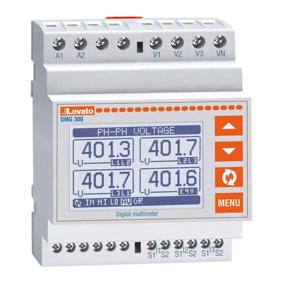
The DMG300 multimeter has been designed to combine the maximum possible easiness of operation
together with a wide choice of advanced functions. Regardless of the compactness of the modular
housing (only 4 modules), the multimeter performance is the same as of high-end devices. The graphic
LCD screen offers a user-friendly interface. The built-in optical infrared interface allows the expansion
through EXM modules.
The rich variety of functions, makes the DMG series multimeters the ideal choice for a wide range of
applications.
DESCRIPTION
– Modular DIN-rail housing, 4U (72mm wide)
– Graphic LCD screen, 128x80 pixels, white backlight, 4 levels of grey
– Membrane keyboard with 4 keys for viewing and setting
– Easy and fast navigation
– Compatible with LV, MV, HV applications
– Texts for measurements, setup and messages in 5 languages
– Reading of more than 300 electrical parameters
– Harmonic analysis of voltage and current up to 31st order
– Optical interface for max 3 EXM series expansion modules
– Advanced programmable I/O functions
– True RMS measurements
– Continuous (gapless) sampling
– High accuracy.
KEYBOARD FUNCTIONS
L and M keys - Used to scroll display pages, to select among possible choices, and to modify settings
(increment-decrement).
key - Used to rotate through sub-pages, to confirm a choice, to switch between viewing modes.
MENU key - Used to enter or exit from viewing and setting menus.
VIEWING OF MEASUREMENTS
– The L and M keys allow to scroll the pages of viewed measurements one by one. The page being
viewed is written in the title bar.
– Some of the readings may not be shown, depending on the programming and the wiring of the device
(for instance, if programmed-wired for a three-phase without neutral system, L-N voltage page is not
shown).
– For every page, the
key allows to rotate through several sub-pages (for instance to show the
highest/lowest peak for the selected readings).
– The sub-page viewed is indicated in the status bar on the bottom of the display by one of the
following icons:
• IN = Instantaneous value - Actual instantaneous value of the reading, shown by default every time
the page is changed.
• HI = Highest peak - Highest peak of the instantaneous value of the relative reading. The HIGH
values are stored and kept even when auxiliary power is removed.
They can be cleared using the dedicated command (see commands menu).
• LO = Lowest peak - Lowest value of the reading, stored from the time the DMG power-on.
It is reset using the same command used for HI values.
• AV = Average value -
Time-integrated value of the reading. Allows showing measurements with slow variations.
See integration menu in setup chapter.
GB
I
DMG300
GB
Available in English at www.LovatoElectric.com/I340IGBFE.pdf
F
Available in French at www.LovatoElectric.com/I340IGBFE.pdf
D
Available in German at www.LovatoElectric.com/I340D.pdf
DIGITAL MULTIMETER
Installation manual
MULTIMETRO DIGITALE
Manuale d'installazione
ATTENZIONE!!
– Leggere attentamente il manuale prima dell'utilizzo e l'installazione.
– Questi apparecchi devono essere installati da personale qualificato, nel rispetto delle vigenti normative
impiantistiche, allo scopo di evitare danni a persone o cose.
– Prima di qualsiasi intervento sullo strumento, togliere tensione dagli ingressi di misura e di
alimentazione e cortocircuitare i trasformatori di corrente.
– Il costruttore non si assume responsabilità in merito alla sicurezza elettrica in caso di utilizzo
improprio del dispositivo.
– I prodotti descritti in questo documento sono suscettibili in qualsiasi momento di evoluzioni o di
modifiche. Le descrizioni ed i dati a catalogo non possono pertanto avere alcun valore contrattuale.
– Un interruttore o disgiuntore va compreso nell'impianto elettrico dell'edificio. Esso deve trovarsi in
stretta vicinanza dell'apparecchio ed essere facilmente raggiungibile da parte dell'operatore.
Deve essere marchiato come il dispositivo di interruzione dell'apparecchio: IEC/ EN 61010-1 § 6.11.2.
– Installare lo strumento in contenitore e/o quadro elettrico con grado di protezione minimo IP40.
– Pulire lo strumento con panno morbido, non usare prodotti abrasivi, detergenti liquidi o solventi.
INTRODUZIONE
Il multimetro DMG300 è stato progettato per unire la massima semplicità di utilizzo con una ampia scelta
di funzioni avanzate.
Nonostante l'estrema compattezza del contenitore modulare (solo 4 moduli), le prestazioni del
multimetro sono le stesse di un apparecchio di alto livello. Il display grafico LCD consente una interfaccia
utente intuitiva. L'interfaccia ottica ad infrarossi consente l'espansione tramite la vasta gamma di moduli
EXM... . La ricca dotazione di funzioni fa dei multimetri serie DMG la soluzione ideale per un campo di
applicazioni estremamente ampio.
DESCRIZIONE
– Esecuzione modulare 4U (72mm) per guida DIN.
– Display LCD grafico 128x80 pixel, retroilluminato, 4 livelli di grigio.
– 4 tasti a membrana per visualizzazione ed impostazione.
– Navigazione rapida e semplice.
– Compatibile con reti BT, MT e AT.
– Testi per misure, impostazioni e messaggi in 5 lingue.
– Più di 300 grandezze elettriche misurate.
– Analisi armonica di tensione e corrente fino al 31.mo ordine.
– Interfaccia ottica per max 3 moduli di espansione serie EXM.
– Funzioni di I/O avanzate programmabili.
– Misure in vero valore efficace (TRMS).
– Acquisizione continua (gapless).
– Elevata accuratezza.
FUNZIONE DEI TASTI FRONTALI
Tasti L e M - Servono per lo scorrimento fra le pagine video, per la selezione fra le possibili scelte
presentate a display e per la modifica di impostazioni (incremento/decremento).
Tasto
- Serve per lo scorrimento delle sotto-pagine, per confermare una scelta effettuata e per
passare da una modalità all' altra di visualizzazione.
Tasto MENU - Serve per entrare o uscire dai vari menu sia di visualizzazione che di impostazione.
VISUALIZZAZIONE DELLE MISURE
– I tasti L e M consentono di scorrere le pagine di visualizzazione misure una per volta. La pagina
attuale è riconoscibile tramite la barra del titolo.
– Alcune delle misure potrebbero non essere visualizzate in funzione della programmazione e del
collegamento dell'apparecchio (ad esempio se programmato per un sistema senza neutro le misure
riferite al neutro non vengono visualizzate).
– Per ogni pagina, il tasto
consente di accedere a delle sotto-pagine (ad esempio per visualizzare i
valori massimi e minimi registrati per la misura selezionata).
– La sottopagina visualizzata correntemente è indicata in basso a sinistra da una delle seguenti icone:
• IN = Valore istantaneo - Valore istantaneo attuale della misura, visualizzato di default ogni volta
che si cambia pagina.
• HI = Valore massimo istantaneo - Valore più alto misurato dal multimetro per la relativa misura. I
valori HIGH vengono memorizzati e mantenuti anche in assenza di alimentazione. Possono essere
azzerati tramite apposito comando (vedere menu comandi).
• LO = Valore minimo istantaneo - Valore più basso misurato dal multimetro dal momento della
messa in tensione. Viene resettato con lo stesso comando usato per i valori HI.
• AV = Valore integrato - Valore della misura integrato (mediato) nel tempo. Consente di vedere una
misura con variazioni lente. Vedere menu Integrazione.
I
Available in Italian at www.LovatoElectric.com/I340IGBFE.pdf
E
Available in Spanish at www.LovatoElectric.com/I340IGBFE.pdf
1
Advertisement
Table of Contents

Related Manuals for LOVATO ELECTRIC DMG300


Summary of Contents for LOVATO ELECTRIC DMG300
- Page 1 The DMG300 multimeter has been designed to combine the maximum possible easiness of operation Il multimetro DMG300 è stato progettato per unire la massima semplicità di utilizzo con una ampia scelta together with a wide choice of advanced functions. Regardless of the compactness of the modular di funzioni avanzate.
-
Page 2: Display Page Navigation
• MD = Maximum Demand - Maximum peak of the integrated value. Stored in non-volatile memory • MD = Massimo valore integrato - Valore massimo del valore integrato (max demand). and it is resettable with dedicated command. Rimane memorizzato in memoria non volatile ed è resettabile con apposito comando. •... - Page 3 TABLE OF DISPLAY PAGES TABELLA DELLE PAGINE DEL DISPLAY Selection with L and M Selection with Selezione con L e M Selezione con N° PAGE / PAGINE SUB PAGES / SOTTOPAGINE PHASE-TO-PHASE VOLTAGES / TENSIONI CONCATENATE V(L1-L2), V(L2-L3), V(L3-L1), V(LL)EQV PHASE-TO-NEUTRAL VOLTAGES / TENSIONI DI FASE V(L1-N), V(L2-N), V(L3-N), V(L-N)EQV PHASE AND NEUTRAL CURRENTS / CORRENTI DI FASE E DI NEUTRO...
-
Page 4: Menu Principale
MAIN MENU MENU PRINCIPALE – The main menu is made up of a group of graphic icons (shortcuts) that allow rapid access to – Il menu principale è costituito da un insieme di icone grafiche che permettono l’accesso rapido alle measurements and settings. - Page 5 – I canali di comunicazione possono funzionare contemporaneamente. – Activating the Gateway function, it is possible to use a DMG300 with both an Ethernet port and a – Attivando la funzione Gateway, è possibile avere un DMG300 equipaggiato con una porta Ethernet ed...
-
Page 6: Impostazione Dei Parametri (Setup)
PARAMETER SETTING (SETUP) IMPOSTAZIONE DEI PARAMETRI (SETUP) – From normal viewing, press MENU to recall the main menu, then select icon and press – Dalla normale visualizzazione misure, premere MENU per richiamare il menu principale,quindi open the setup menu screen. selezionare l’icona e premere per accedere al menu impostazioni. -
Page 7: Parameter Table
– When the editing screen is displayed, the parameter setting can be modified with L Mkeys. – Quando si è in modalità modifica, il valore può essere modificato con L e M. Vengono visualizzati The screen shows the new setting, a graphic bar that shows the setting range, the maximum and anche una barra grafica che indica il range di impostazione, i valori minimi e massimi possibili, il minimum values, the previous setting and factory defaults. -
Page 8: Commands Menu
M03 - PASSWORD / PASSWORD Default Range P03.01 Enable passwords OFF-ON Utilizzo password P03.02 User level password 1000 0-9999 Password livello Utente P03.03 Advanced level password 2000 0-9999 Password livello Avanzato P03.01 - If set to OFF, password management is disabled and the access to setup parameters and P03.01 - Se impostato ad OFF, la gestione delle password è... -
Page 9: Wiring Test
WIRING TEST TEST DI COLLEGAMENTO – The wiring test allows to verify if the connection of the DMG device has been executed properly. – Il test di collegamento consente di verificare se l’installazione del multimetro è stata effettuata – To be able to execute the test, the device must be connected to an active plant, with the following correttamente. -
Page 10: Technical Characteristics
TECHNICAL CHARACTERISTICS Auxiliary supply Insulation Rated voltage Us 100...240V Rated insulation voltage Ui 690V 110...250V Rated impulse withstand voltage Uimp 9.5kV Operating voltage range 85...264V Power frequency withstand voltage 5.2kV 93.5...300V Auxiliary supply and voltage input connections Frequency range 45...66Hz Type of terminal Screw (fixed) Power consumption/dissipation... -
Page 11: Caratteristiche Tecniche
CARATTERISTICHE TECNICHE Alimentazione ausiliaria Isolamento Tensione nominale Us 100...240V Tensione nominale d’isolamento Ui 690V 110...250V Tensione nominale di tenuta a impulso Uimp 9,5kV Limiti di funzionamento 85...264V Tensione di tenuta a frequenza d’esercizio 5,2kV 93,5...300V Connessioni circuito alimentazione/misura tensioni Frequenza 45...66Hz Tipo di morsetti A vite (fissi) -
Page 12: Wiring Diagrams
WIRING DIAGRAMS SCHEMI DI CONNESSIONE 3-phase connection with or without neutral 2-phase connection Connessione trifase con o senza neutro Connessione bifase P01.07 = L1-L2-L3-N L1-L2-L3 P01.07 = L1-N-L2 100...240VAC 100...240VAC 110...250VDC 110...250VDC V2 V3 S1 S2 S1 S2 S1 S2 -- - AUX SUPPLY VOLTAGE...
Need help?
Do you have a question about the DMG300 and is the answer not in the manual?
Questions and answers