Table of Contents
Advertisement
Available languages
Available languages
Quick Links
LOVATO ELECTRIC S.P.A.
24020 GORLE (BERGAMO) ITALIA
VIA DON E. MAZZA, 12
TEL. 035 4282111
FAX (Nazionale): 035 4282200
FAX (International): +39 035 4282400
L
E
E-mail info@
ovato
lectric.com
L
E
Web
www.
ovato
lectric.com
WARNING!
– Carefully read the manual before the installation or use.
– This equipment is to be installed by qualified personnel, complying to current standards, to avoid
damages or safety hazards.
– Before any maintenance operation on the device, remove all the voltages from measuring and supply inputs and short-
circuit the CT input terminals.
– The manufacturer cannot be held responsible for electrical safety in case of improper use of the equipment.
– Products illustrated herein are subject to alteration and changes without prior notice. Technical data and descriptions in
the documentation are accurate, to the best of our knowledge, but no liabilities for errors, omissions or contingencies
arising there from are accepted.
– A circuit breaker must be included in the electrical installation of the building. It must be installed close by the
equipment and within easy reach of the operator. It must be marked as the disconnecting device of the equipment:
IEC /EN 61010-1 § 6.11.2.
– Clean the device with a soft dry cloth; do not use abrasives, liquid detergents or solvents.
ATTENTION !
– Lire attentivement le manuel avant toute utilisation et installation.
– Ces appareils doivent être installés par un personnel qualifié, conformément aux normes en vigueur en
matière d'installations, afin d'éviter de causer des dommages à des personnes ou choses.
– Avant toute intervention sur l'instrument, mettre les entrées de mesure et d'alimentation hors tension et court-circuiter
les transformateurs de courant.
– Le constructeur n'assume aucune responsabilité quant à la sécurité électrique en cas d'utilisation impropre du
dispositif.
– Les produits décrits dans ce document sont susceptibles d'évoluer ou de subir des modifications à n'importe quel
moment. Les descriptions et caractéristiques techniques du catalogue ne peuvent donc avoir aucune valeur
contractuelle.
– Un interrupteur ou disjoncteur doit être inclus dans l'installation électrique du bâtiment. Celui-ci doit se trouver tout
près de l'appareil et l'opérateur doit pouvoir y accéder facilement. Il doit être marqué comme le dispositif d'interruption
de l'appareil : IEC/ EN 61010-1 § 6.11.2.
– Nettoyer l'appareil avec un chiffon doux, ne pas utiliser de produits abrasifs, détergents liquides ou solvants.
ACHTUNG!
– Dieses Handbuch vor Gebrauch und Installation aufmerksam lesen.
– Zur Vermeidung von Personen- und Sachschäden dürfen diese Geräte nur von qualifiziertem
Fachpersonal und unter Befolgung der einschlägigen Vorschriften installiert werden.
– Vor jedem Eingriff am Instrument die Spannungszufuhr zu den Messeingängen trennen und die Stromwandler
kurzschlieβen.
– Bei zweckwidrigem Gebrauch der Vorrichtung übernimmt der Hersteller keine Haftung für die elektrische Sicherheit.
– Die in dieser Broschüre beschriebenen Produkte können jederzeit weiterentwickelt und geändert werden. Die im Katalog
enthaltenen Beschreibungen und Daten sind daher unverbindlich und ohne Gewähr.
– In die elektrische Anlage des Gebäudes ist ein Ausschalter oder Trennschalter einzubauen. Dieser muss sich in
unmittelbarer Nähe des Geräts befinden und vom Bediener leicht zugänglich sein. Er muss als Trennvorrichtung für das
Gerät gekennzeichnet sein: IEC/ EN 61010-1 § 6.11.2.
– Das Gerät mit einem weichen Tuch reinigen, keine Scheuermittel, Flüssigreiniger oder Lösungsmittel verwenden.
ADVERTENCIA
– Leer atentamente el manual antes de instalar y utilizar el regulador.
– Este dispositivo debe ser instalado por personal cualificado conforme a la normativa de instalación
vigente a fin de evitar daños personales o materiales.
– Antes de realizar cualquier operación en el dispositivo, desconectar la corriente de las entradas de alimentación y
medida, y cortocircuitar los transformadores de corriente.
– El fabricante no se responsabilizará de la seguridad eléctrica en caso de que el dispositivo no se utilice de forma
adecuada.
– Los productos descritos en este documento se pueden actualizar o modificar en cualquier momento. Por consiguiente,
las descripciones y los datos técnicos aquí contenidos no tienen valor contractual.
– La instalación eléctrica del edificio debe disponer de un interruptor o disyuntor. Éste debe encontrarse cerca del
dispositivo, en un lugar al que el usuario pueda acceder con facilidad. Además, debe llevar el mismo marcado que el
interruptor del dispositivo (IEC/ EN 61010-1 § 6.11.2).
– Limpiar el dispositivo con un trapo suave; no utilizar productos abrasivos, detergentes líquidos ni disolventes.
UPOZORNĚNÍ
– Návod se pozorně pročtěte, než začnete regulátor instalovat a používat.
– Tato zařízení smí instalovat kvalifikovaní pracovníci v souladu s platnými předpisy a normami pro předcházení
úrazů osob či poškození věcí.
– Před jakýmkoli zásahem do přístroje odpojte měřicí a napájecí vstupy od napětí a zkratujte transformátory proudu.
– Výrobce nenese odpovědnost za elektrickou bezpečnost v případě nevhodného používání regulátoru.
– Výrobky popsané v tomto dokumentu mohou kdykoli projít úpravami či dalším vývojem. Popisy a údaje uvedené v katalogu nemají
proto žádnou smluvní hodnotu.
– Spínač či odpojovač je nutno zabudovat do elektrického rozvodu v budově. Musejí být nainstalované v těsné blízkosti přístroje a
snadno dostupné pracovníku obsluhy. Je nutno ho označit jako vypínací zařízení přístroje: IEC/ EN 61010-1 § 6.11.2.
– Přístroj čistěte měkkou utěrkou, nepoužívejte abrazivní produkty, tekutá čistidla či rozpouštědla.
AVERTIZARE!
– Citiţi cu atenţie manualul înainte de instalare sau utilizare.
– Acest echipament va fi instalat de personal calificat, în conformitate cu standardele actuale, pentru a evita
deteriorări sau pericolele.
– Înainte de efectuarea oricărei operaţiuni de întreţinere asupra dispozitivului, îndepărtaţi toate tensiunile de la intrările de măsurare
şi de alimentare şi scurtcircuitaţi bornele de intrare CT.
– Producătorul nu poate fi considerat responsabil pentru siguranţa electrică în caz de utilizare incorectă a echipamentului.
– Produsele ilustrate în prezentul sunt supuse modificărilor şi schimbărilor fără notificare anterioară. Datele tehnice şi descrierile din
documentaţie sunt precise, în măsura cunoştinţelor noastre, dar nu se acceptă nicio răspundere pentru erorile, omiterile sau
evenimentele neprevăzute care apar ca urmare a acestora.
– Trebuie inclus un disjunctor în instalaţia electrică a clădirii. Acesta trebuie instalat aproape de echipament şi într-o zonă uşor
accesibilă operatorului. Acesta trebuie marcat ca fiind dispozitivul de deconectare al echipamentului: IEC/EN 61010-1 § 6.11.2.
– Curăţaţi instrumentul cu un material textil moale şi uscat; nu utilizaţi substanţe abrazive, detergenţi lichizi sau solvenţi.
GB
Digital power analyzer - Power transducer
Installation manual
DMG900 - DMG900T
ATTENZIONE!
– Leggere attentamente il manuale prima dell'utilizzo e l'installazione.
– Questi apparecchi devono essere installati da personale qualificato, nel rispetto delle vigenti normative
impiantistiche, allo scopo di evitare danni a persone o cose.
– Prima di qualsiasi intervento sullo strumento, togliere tensione dagli ingressi di misura e di alimentazione e
cortocircuitare i trasformatori di corrente.
– Il costruttore non si assume responsabilità in merito alla sicurezza elettrica in caso di utilizzo improprio del dispositivo.
– I prodotti descritti in questo documento sono suscettibili in qualsiasi momento di evoluzioni o di modifiche. Le
descrizioni ed i dati a catalogo non possono pertanto avere alcun valore contrattuale.
– Un interruttore o disgiuntore va compreso nell'impianto elettrico dell'edificio. Esso deve trovarsi in stretta vicinanza
dell'apparecchio ed essere facilmente raggiungibile da parte dell'operatore. Deve essere marchiato come il dispositivo di
interruzione dell'apparecchio: IEC/ EN 61010-1 § 6.11.2.
– Pulire l'apparecchio con panno morbido, non usare prodotti abrasivi, detergenti liquidi o solventi.
UWAGA!
– Przed użyciem i instalacją urządzenia należy uważnie przeczytać niniejszą instrukcję.
– W celu uniknięcia obrażeń osób lub uszkodzenia mienia tego typu urządzenia muszą być instalowane przez
wykwalifikowany personel, zgodnie z obowiązującymi przepisami.
– Przed rozpoczęciem jakichkolwiek prac na urządzeniu należy odłączyć napięcie od wejść pomiarowych i zasilania oraz zewrzeć
zaciski przekładnika prądowego.
– Producent nie przyjmuje na siebie odpowiedzialności za bezpieczeństwo elektryczne w przypadku niewłaściwego użytkowania
urządzenia.
– Produkty opisane w niniejszym dokumencie mogą być w każdej chwili udoskonalone lub zmodyfikowane. Opisy oraz dane
katalogowe nie mogą mieć w związku z tym żadnej wartości umownej.
– W instalacji elektrycznej budynku należy uwzględnić przełącznik lub wyłącznik automatyczny. Powinien on znajdować się w
bliskim sąsiedztwie urządzenia i być łatwo osiągalny przez operatora. Musi być oznaczony jako urządzenie służące do wyłączania
urządzenia: IEC/ EN 61010-1 § 6.11.2.
– Urządzenie należy czyścić miękką szmatką, nie stosować środkow ściernych, płynnych detergentow lub rozpuszczalnikow.
ПРЕДУПРЕЖДЕНИЕ!
– Прежде чем приступать к монтажу или эксплуатации устройства, внимательно ознакомьтесь с одержанием
настоящего руководства.
– Во избежание травм или материального ущерба монтаж должен существляться только квалифицированным персоналом
в соответствии с действующими нормативами.
– Перед проведением любых работ по техническому обслуживанию устройства необходимо обесточить все измерительные
и питающие входные контакты, а также замкнуть накоротко входные контакты трансформатора тока (ТТ).
– Производитель не несет ответственность за обеспечение электробезопасности в случае ненадлежащего использования
устройства.
– Изделия, описанные в настоящем документе, в любой момент могут подвергнуться изменениям или
усовершенствованиям. Поэтому каталожные данные и описания не могут рассматриваться как действительные с точки
зрения контрактов
– Электрическая сеть здания должна быть оснащена автоматическим выключателем, который должен быть расположен
вблизи оборудования в пределах доступа оператора. Автоматический выключатель должен быть промаркирован как
отключающее устройство оборудования: IEC /EN 61010-1 § 6.11.2.
– Очистку устройства производить с помощью мягкой сухой ткани, без применения абразивных материалов, жидких
моющих средств или растворителей.
DİKKAT!
– Montaj ve kullanımdan önce bu el kitabını dikkatlice okuyunuz.
– Bu aparatlar kişilere veya nesnelere zarar verme ihtimaline karşı yürürlükte olan sistem kurma normlarına göre
kalifiye personel tarafından monte edilmelidirler
– Aparata (cihaz) herhangi bir müdahalede bulunmadan önce ölçüm girişlerindeki gerilimi kesip akım transformatörlerinede kısa
devre yaptırınız.
– Üretici aparatın hatalı kullanımından kaynaklanan elektriksel güvenliğe ait sorumluluk kabul etmez.
– Bu dokümanda tarif edilen ürünler her an evrimlere veya değişimlere açıktır. Bu sebeple katalogdaki tarif ve değerler herhangi bir
bağlayıcı değeri haiz değildir.
– Binanın elektrik sisteminde bir anahtar veya şalter bulunmalıdır. Bu anahtar veya şalter operatörün kolaylıkla ulaşabileceği yakın
bir yerde olmalıdır. Aparatı (cihaz) devreden çıkartma görevi yapan bu anahtar veya şalterin markası: IEC/ EN 61010-1 § 6.11.2.
– Aparatı (cihaz) sıvı deterjan veya solvent kullanarak yumuşak bir bez ile siliniz aşındırıcı temizlik ürünleri kullanmayınız.
The complete operating manual is downloadable from website www.lovatoelectric.com
Il manuale operativo completo è scaricabile dal sito www.lovatoelectric.com
G
B
1
Advertisement
Table of Contents

Related Manuals for LOVATO ELECTRIC DMG900L01


Summary of Contents for LOVATO ELECTRIC DMG900L01
- Page 1 Digital power analyzer - Power transducer Installation manual LOVATO ELECTRIC S.P.A. 24020 GORLE (BERGAMO) ITALIA VIA DON E. MAZZA, 12 TEL. 035 4282111 FAX (Nazionale): 035 4282200 FAX (International): +39 035 4282400 DMG900 - DMG900T E-mail info@ ovato lectric.com www.
-
Page 2: Touch-Screen Functions
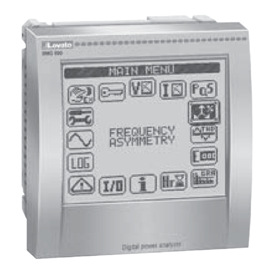
INTRODUCTION DMG900 - The DMG900 power analyzer has been designed to combine the maximum possible easiness of operation together with a wide choice of advanced functions. Thanks to its flush-mount 96x96mm housing, the DMG900 joins the modern design of the front panel with the tool-less mounting of the device body and the expansion capability of the rear panel, where it is possible to mount plug-in modules of EXP… series. The graphic, touch-screen LCD display offers a user-friendly interface. - Page 3 – Some of the readings may not be shown, depending on the programming and the wiring of the device (for instance, if programmed-wired for a three-phase without neutral system, L-N voltage page is not shown) – For every page, it is possible to access several sub-pages (for instance to show the highest/lowest peak for the selected readings) simply touching the correspondent icon –...
- Page 4 SELECTION OF INTERFACE TYPE (DMG900T) – The DMG900T is equipped with three interface ports that can be used alternatively (it is not possible to connect more than one interface at a time). – The selection of the active ports done through a couple of DIP-switches, according to the following table: DESCRIPTION Remote display DMG900RD RS485 (COM1)
- Page 5 – The following table lists the available sub-menus: Cod. MENU DESCRIPTION GENERAL Detailed data of the installation UTILITY Language, backlight, display pages, etc. PASSWORD Access codes enabling INTEGRATION Readings integration time HOUR COUNTER Hour counter enabling TREND GRAPH Trend graph reading and scale COMMUNICATION (COMn) Communication ports parameters (DMG210) LIMIT THRESHOLDS (LIMn)
- Page 6 PARAMETER TABLE M01 - GENERAL Default Range P01.01 CT primary 1-10000 P01.02 CT secondary P01.03 Rated voltage Aut / 50-500000 P01.04 Use VT OFF-ON P01.05 VT primary 50-500000 P01.06 VT secondary 50-500 P01.07 Wiring L1-L2-L3-N L1-L2-L3-N L1-L2-L3 L1-L2-L3-N BIL L1-L2-L3 BIL L1-N-L2 L1-N P01.08...
- Page 7 DMG900 INSTALLATION – DMG900 is designed for flush-mount installation according to IEC 61554 – Insert the device into the panel hole, making sure that the gasket is properly positioned between the panel and the device front frame – From inside the panel, for each four of the fixing clips, position the clip in one of the two sliding guide, then press on the clip corner until the second guide snaps in –...
-
Page 8: Wiring Diagrams
WIRING DIAGRAMS 3-phase connection whit or without neutral, V4 and neutral current 2-phase connection whit or without V4 and neutral current P01.07 = L1-L2-L3-N L1-L2-L3 P01.07 = L1-N-L2 100...440VAC 100...440VAC 110...250VDC 110...250VDC 12...48VDC 12...48VDC - -- V2 V3 -- - S1 S2 AUX SUPPLY VOLTAGE... - Page 9 DMG900 TERMINALS POSITION A1/- A2/+ DMG900 MECHANICAL DIMENSIONS (mm) DMG900T TERMINALS POSITION RS232 DATA RS485 DISPLAY A1/- A2/+ DMG900T MECHANICAL DIMENSIONS (mm) 84.7 19.8 54.2...
- Page 10 DMG900T COMMUNICATION PORTS WIRING DIAGRAMS Connection with remote Display RS232 RJ45 standard cable 3mt MAX DATA RS485 DISPLAY A1/- A2/+ Connection with PC RS232 DATA RS485 RS232 51C2 cable DISPLAY A1/- A2/+ RS485 connection B SG RS485 RS485 DMG900T n°31 DMG900T n°1 Repeat this wiring diagram up to 255 devices...
-
Page 11: Technical Characteristics
TECHNICAL CHARACTERISTICS Auxiliary supply Insulation Rated voltage Us ‚ 100 - 440V Rated insulation voltage Ui 690V 110 - 250V Rated impulse withstand voltage Uimp 9.5kV Operating voltage range 90 - 484V Power frequency withstand voltage 5.2kV 93.5 - 300V Auxiliary supply and voltage input connections Frequency 45 - 66Hz... - Page 12 Analizzatore digitale di potenza - Trasduttore di potenza Manuale d’installazione LOVATO ELECTRIC S.P.A. 24020 GORLE (BERGAMO) ITALIA VIA DON E. MAZZA, 12 TEL. 035 4282111 FAX (Nazionale): 035 4282200 FAX (International): +39 035 4282400 DMG900 - DMG900T E-mail info@ ovato lectric.com...
-
Page 13: Visualizzazione Delle Misure
INTRODUZIONE DMG900 - L’analizzatore di potenza DMG900 è stato progettato per unire la massima semplicità di utilizzo con una ampia scelta di funzioni avanzate. In esecuzione per montaggio a pannello con dimensioni standard 96x96mm, il DMG900 unisce il moderno design del frontale alla praticità di montaggio e alla possibilità di espansione sul retro, dove è possibile alloggiare moduli della serie EXP..Il display grafico LCD con touch screen consente una interfaccia utente chiara ed intuitiva. -
Page 14: Menu Principale
– Alcune delle misure potrebbero non essere visualizzate in funzione della programmazione e del collegamento dell’apparecchio (ad esempio se programmato per un sistema senza neutro le misure riferite al neutro non vengono visualizzate). – Per ogni pagina, è possibile accedere a delle sotto-pagine (ad esempio per visualizzare i valori massimi e minimi registrati per la misura selezionata), semplicemente toccando l’icona corrispondente. –... -
Page 15: Impostazione Dei Parametri (Setup)
SELEZIONE TIPO DI INTERFACCIA (DMG900T) – Il DMG900T è provvisto di tre porte di interfaccia che possono essere utilizzate alternativamente (non è possibile collegare più di una interfaccia contemporaneamente). – La selezione della porta attiva viene effettuata tramite una coppia di DIP switch, secondo la seguente tabella: DESCRIZIONE Display remoto DMG900RD RS485 (COM1) - Page 16 – Nella seguente tabella sono elencati i sottomenu disponibili : Cod.. MENU DESCRIZIONE GENERALE Dati caratteristici dell’impianto UTILITA’ Lingua, luminosità, pagine display ecc. PASSWORD Abilitazione protezione accesso INTEGRAZIONE Tempi di integrazione misure CONTAORE Abilitazione contaore GRAFICO TREND Definizione misura e scala grafico trend COMUNICAZIONE (COMn) COMCOMn Porte di comunicazione SOGLIE LIMITE (LIMn)
- Page 17 TABELLA PARAMETRI M01 - GENERALE Default Range P01.01 Primario TA 1-10000 P01.02 Secondario TA P01.03 Tensione nominale Aut / 50-500000 P01.04 Utilizzo TV OFF-ON P01.05 Primario TV 50-500000 P01.06 Secondario TV 50-500 P01.07 Tipo di collegamento L1-L2-L3-N L1-L2-L3-N L1-L2-L3 L1-L2-L3-N BIL L1-L2-L3 BIL L1-N-L2 L1-N...
- Page 18 INSTALLAZIONE DMG900 – DMG900 è destinato al montaggio da incasso secondo IEC61554. – Inserire il multimetro nel foro del pannello dalla parte frontale, accertandosi che la guarnizione sia posizionata correttamente fra il pannello e la cornice dello strumento. – Dall’interno del quadro, per ciascuna delle quattro clips di fissaggio, posizionare la clip in una delle due guide laterali, premendo successivamente sullo spigolo della clip in modo da agganciare a scatto anche la seconda guida.
- Page 19 SCHEMI DI CONNESSIONE Connessione trifase con o senza neutro, V4 e corrente di neutro Connessione bifase con o senza V4 e corrente di neutro P01.07 = L1-L2-L3-N L1-L2-L3 P01.07 = L1-N-L2 100...440VAC 100...440VAC 110...250VDC 110...250VDC 12...48VDC 12...48VDC - -- V2 V3 -- - S1 S2 AUX SUPPLY...
- Page 20 DISPOSIZIONE MORSETTI DMG900 A1/- A2/+ DIMENSIONI MECCANICHE DMG900 (mm) DISPOSIZIONE MORSETTI DMG900T RS232 DATA RS485 DISPLAY A1/- A2/+ DIMENSIONI MECCANICHE DMG900T (mm) 84.7 19.8 54.2...
- Page 21 SCHEMI DI CONNESSIONE PORTE DI COMUNICAZIONE DMG900T Connessione con display remota RS232 RJ45 standard cable 3mt MAX DATA RS485 DISPLAY A1/- A2/+ Connessione con PC RS232 DATA RS485 RS232 51C2 cable DISPLAY A1/- A2/+ Connessione mediante RS485 B SG RS485 RS485 DMG900T n°31 DMG900T n°1...
- Page 22 CARATTERISTICHE TECNICHE Alimentazione ausiliaria Isolamento Tensione nominale Us ‚ 100 - 440V Tensione nominale d’isolamento Ui 690V 110 - 250V Tensione nominale di tenuta a impulso Uimp 9,5kV Limiti di funzionamento 90 - 484V Tensione di tenuta a frequenza d’esercizio 5,2kV 93,5 - 300V Connessioni circuito alimentazione/misura tensioni...
Need help?
Do you have a question about the DMG900L01 and is the answer not in the manual?
Questions and answers