
Related Manuals for RHEONIK RHE Series


Summary of Contents for RHEONIK RHE Series
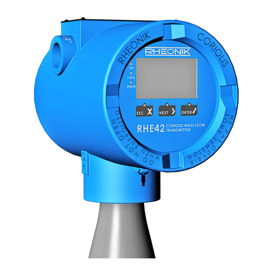
- Page 1 RHE Coriolis transmitter Type RHE42 Version 02 © 2021 Read the instructions prior to performing any task!
- Page 2 Rheonik Messtechnik GmbH Rudolf-Diesel-Str. 5 85235 Odelzhausen Telephone: + 49 8134 9341-0 Fax: + 49 8134 9341-41 Email: info@rheonik.com Internet: www.rheonik.com Rev.: BA01RHE42202108 As at 08/21 – We reserve the right to make technical changes in the course of further development work...
- Page 3 This installation guide is protected by copyright law. Any use that goes beyond the strict limits set by copyright law is forbidden and liable for prosecution without the prior consent of Rheonik Messtechnik GmbH. This also applies to any reproduction, translation and microfilming in addition to saving and editing in electronic media. Any infringements will be...
- Page 4 Foreword RHE Coriolis transmitter Type RHE42 4 / 109...
-
Page 5: Table Of Contents
Table of contents Table of contents About this guide..........General information. - Page 6 Table of contents Start-up........... . . Function of the keys on the RHE42 Coriolis transmitter.
-
Page 7: About This Guide
About this guide About this guide General information This installation guide contains important information regarding how to install, start up, and safely operate the RHE42 Coriolis transmitter as intended. Care- fully read the information in this installation guide before starting any work with or on the RHE42 Coriolis transmitter, and make sure you have understood everything. -
Page 8: Symbols Used In This Guide
About this guide Symbols used in this guide In this installation guide, sections containing particularly important information are identified in line with the type of information they contain, e.g. instructions, lists or references. Symbol Meaning Instruction; step in a process If you need to perform several steps one after the other, they will be numbered based on their chronological sequence. -
Page 9: Safety
Safety Safety To ensure that the RHE42 Coriolis transmitter is operated safely and as intended, it is essential to familiarise yourself with the basic safety instructions and safety regulations. It is also essential to comply with the rules and regula- tions on accident prevention that apply at the installation location. -
Page 10: How Warnings Are Structured And What They Mean
Safety How warnings are structured and what they mean When performing different types of work either with the or on the RHE42 Coriolis transmitter, the personnel carry out steps that could entail hazards. These steps are therefore preceded by a warning. Warnings are always structured as follows: ■... -
Page 11: Safety And Associated Safety Measures
Safety Safety and associated safety measures DANGER Risk to life if the information in this installation guide is not observed! If the information in this installation guide is not observed, this will result in serious injury or death. − Read and observe the information in this installation guide before working either with the or on the RHE42 Coriolis transmitter. -
Page 12: Personnel Qualifications
Safety ■ Modifications, attachments and conversions Any modifications to or attachments and conversions on the RHE42 Coriolis transmitter may make the safety devices less effective or entirely ineffective, resulting in unforeseeable hazards. – Do not carry out any technical modifications or extensions on the RHE42 Coriolis transmitter. -
Page 13: Intended Use
Intended use Intended use The RHE42 Coriolis transmitter displays the measured values for RHM Coriolis sensors. It can display the mass flow of liquids and gases as well as the medium density and medium temperature. In addition, the RHE42 Coriolis transmitter is able to calculate variables such as the volume. - Page 14 Intended use RHE Coriolis transmitter Type RHE42 14 / 109...
-
Page 15: Product Description
Product description Product description RHE42-C* Coriolis transmitter (com- pact version RHE42 Coriolis trans- mitter installed on RHM Coriolis sensor) Fig. 1: RHE42 Coriolis transmitter with RHM Coriolis sensor RHE42 Coriolis transmitter RHM Coriolis sensor Type label Display RHE Coriolis transmitter Type RHE42 15 / 109... - Page 16 Product description RHE42-R* Coriolis transmitter (remote installation) Fig. 2: RHE42 Coriolis transmitter with bracket for installation on the wall RHE42 Coriolis transmitter Installation angle for installation on the wall or a pipe Type label Display Type label Fig. 3: Type label Type label Table with safety limits for the intrinsically safe inputs and outputs Product designation...
- Page 17 Product description Serial number of corresponding RHM Coriolis sensor Customer-specific tag number Permissible ambient temperature Housing classification Permissible power supply ATEX classification ATEX certificate number IECEx classification IECEx certificate number Abbreviation Name Sensor drive Pick-up of measured values Temperature measurement Analogue output Digital output Digital input...
-
Page 18: Model Code
Product description ican market. Detailed information on the protection classes and safety areas Chapter 4.2 ‘Protection classes and safety areas (explosion is provided here: ⮫ protection)’ on page 20 . Model code RHE42- Housing IP65/Type 4 (indoor and outdoor use) with ■... - Page 19 Product description RHE42- xx Digital inputs and digital/analogue outputs (intrinsically safe) ■ Analogue outp. (p) 1x, dig. outp. 2x, HART communication, RS 485 (Modbus – not intrinsically safe) ■ Analogue outp. (p) 2x, dig. outp. 1x, dig. inp. 1x, HART communica- tion, RS 485 (Modbus –...
-
Page 20: Protection Classes And Safety Areas (Explosion Protection)
Product description Protection classes and safety areas (explosion protection) Order Designation Area of application for Area of application for Certified code RHE42 Coriolis transmitter RHM Coriolis sensor according to/by II 2 (1) G Ex db eb [ia Ga] IIC T6 Zone 1, 2;... -
Page 21: Transportation, Storage, Scope Of Delivery
Transportation, storage, scope of delivery Transportation, storage, scope of delivery Transportation Always transport the RHE42 Coriolis transmitter in its original packaging. Storage Store the RHE42 Coriolis transmitter under the following conditions until it is installed: ■ In the original packaging ■... - Page 22 Transportation, storage, scope of delivery RHE Coriolis transmitter Type RHE42 22 / 109...
-
Page 23: Installing The Rhe42 Coriolis Transmitter
Installing the RHE42 Coriolis transmitter Installing the RHE42 Coriolis transmitter There are three ways to install the RHE42 Coriolis transmitter: ■ Installed directly on an RHM Coriolis sensor (RHE42-C*) ex works. See: RHM Coriolis sensor (operation manual) ■ Installed externally on a wall or on a metal plate that is at least 6 mm thick (RHE42-R*) ■... - Page 24 Installing the RHE42 Coriolis transmitter Remove the RHE42 Coriolis transmitter (1) from the wall/mounting plate. NOTICE Damage to property when drilling holes near components. When drilling the holes, there is a risk of damaging com- ponents that are located in or next to the wall. −...
-
Page 25: Installing The Rhe42 Coriolis Transmitter On A Pipe (Rhe42-R*)
Installing the RHE42 Coriolis transmitter Installing the RHE42 Coriolis transmitter on a pipe (RHE42-R*) This installation method requires the ARHE42-H accessory. The pipe onto which the RHE42 Coriolis transmitter will be installed must be made of metal and have a diameter of at least 2 inches / 50 mm. Fig. -
Page 26: Connecting The Rhe42 Coriolis Transmitter
RHE42 Coriolis transmitter. If the connecting cable (ARHE- Cx) is damaged, the RHE42 Coriolis transmitter will need to be returned to Rheonik Messtechnik GmbH for repair. The connecting cable (ARHE-Cx) must not be longer than 20 m. RHE Coriolis transmitter Type RHE42... - Page 27 Connecting the RHE42 Coriolis transmitter WARNING Risk of burns when touching hot surfaces! If you are using an RHM Coriolis sensor with hot liquids and gases, the RHM Coriolis sensor and adjacent components can become very hot. There is a risk of serious burns if you touch hot surfaces.
- Page 28 Connecting the RHE42 Coriolis transmitter Fig. 6: Wiring diagram for the RHE42-R* Coriolis transmitter to the RHM Coriolis sensor RHE42 Coriolis transmitter Blue cable Grounding point Green cable Connecting cable (ARHE-Cx) GNYE Green/yellow cable RHM Coriolis sensor Grey cable Connection terminal Orange cable Drive coil Pink cable...
- Page 29 Connecting the RHE42 Coriolis transmitter Check whether the serial number on the type label of the RHE42 Coriolis transmitter (1) matches the serial number of the RHM Coriolis sensor (3) that you are connecting. The RHE42 Coriolis transmitter is assigned a RHM Cori- olis sensor in the factory.
- Page 30 Connecting the RHE42 Coriolis transmitter Cable colour Signal OG orange Temperature sensor – torsion YE yellow Pick-up coil (A) left + GN green Pick-up coil (A) left - GY grey Pick-up coil (B) right + WH white Pick-up coil (B) right - GNYE green/yellow Shielding Shielding...
-
Page 31: Connecting The Power Supply, Inputs/Outputs And Signal Cables
Connecting the RHE42 Coriolis transmitter Connecting the power supply, inputs/outputs and signal cables to on the RHE42 Coriolis transmitter Assignment when I/O not intrinsically safe Fig. 7: Wiring diagram for RHE42-R* Coriolis transmitter (not intrinsically safe) RHE42 Coriolis transmitter 2.2 Analogue outputs 1.1 Ground screw for shielding connection 2.3 Power supply for the RHE42 Coriolis transmitter Connection terminals... - Page 32 Connecting the RHE42 Coriolis transmitter Terminal Signal Name 485A RS 485 connection (+) 485B RS 485 connection (-) Tab. 7: Terminal assignment for RHE42 Coriolis transmitter Terminal Signal Name Implemented as Active digital output 1 Active digital output 2 Passive digital input 1 B1, EB, EA, S1, 1H Passive digital input 2 B1, EB...
- Page 33 Connecting the RHE42 Coriolis transmitter Fig. 8: Wiring diagram for RHE42-R* Coriolis transmitter (intrinsically safe) RHE42 Coriolis transmitter 2.3 Fieldbus (intrinsically safe) 1.1 Ground screw for shielding connection 2.4 Analogue outputs (intrinsically safe) Connection terminals 2.5 Power supply for RHE42 Coriolis transmitter (not 2.1 Digital outputs (intrinsically safe) intrinsically safe) 2.2 Digital inputs (intrinsically safe)
- Page 34 Connecting the RHE42 Coriolis transmitter Terminal Signal Name 485B RS 485 connection (-) Tab. 9: Terminal assignment for RHE42 Coriolis transmitter Channel Terminal Signal Name Implemented as DO1+ Digital output 1 (+) i1, i2, F2, P2 DO1- Digital output 1 (-) i1, i2, F2, P2 DO2+ Digital output 2 (+)
- Page 35 Connecting the RHE42 Coriolis transmitter Fig. 9: Opening the RHE42 Coriolis transmitter RHE42 Coriolis transmitter Cover plate (only for intrinsically safe inputs and outputs) Screws (only for intrinsically safe inputs and outputs) Cover Remove the cover (D) from the RHE42 Coriolis transmitter (A), for example using a strap spanner.
- Page 36 Connecting the RHE42 Coriolis transmitter Connect the wires to on the RHE42 Coriolis transmitter (A): Figure 7: Wiring diagram for the RHE42-R* (not intrinsically safe) ■ ⮫ ■ Figure 8: Wiring diagram for the RHE42-R* (intrinsically safe) ⮫ The connection terminals are equipped with push-in ter- minals.
-
Page 37: Wiring Diagrams For The Power Supply, Rs485 And Modbus Tcp
Connecting the RHE42 Coriolis transmitter Wiring diagrams for the power supply, RS485 and Modbus TCP 7.3.1 Connecting the power supply The RHE42 Coriolis transmitter requires a regulated DC power supply of 12 to 24 V ±10%. The power consumption is 2 to max. 4 W. Fig. - Page 38 Connecting the RHE42 Coriolis transmitter Fig. 11: RS485 interface connection 70 RS 485 (+) connection 71 RS 485 (-) connection Connect the Tx+ / Rx+ connection to the RS 485 (+) connection (70). Connect the Tx- / Rx- connection to the RS 485 (-) connection (71). Switching the termination switch Fig.
-
Page 39: Connecting The Modbus Tcp Interface
Connecting the RHE42 Coriolis transmitter Slide the termination switch (C) to the required position: ■ The ON position (C1) by sliding it to the right. ■ The OFF position (C2) by sliding it to the left. Fit the cover (A) onto the RHE42 Coriolis transmitter (B), for example using a strap spanner. - Page 40 Connecting the RHE42 Coriolis transmitter In FISCO bus systems, the barrier/supply isolator comes built Fig. 14: Foundation Fieldbus / Profibus interface connection 77 Foundation Fieldbus FFH1 (FISCO) (+) connection (version FF, F2) 78 Foundation Fieldbus FFH1 (FISCO) (-) connection (version FF, F2) 77 Profibus PA (FISCO) (+) connection (version PA, P2) 78 Profibus PA (FISCO) (-) connection (version PA, P2) Connect the positive output of the FISCO bus system to the Foundation...
-
Page 41: Wiring Diagrams For Non-Intrinsically Safe Inputs And Outputs
Connecting the RHE42 Coriolis transmitter Wiring diagrams for non-intrinsically safe inputs and outputs 7.4.1 Connecting non-intrinsically safe analogue outputs Fig. 15: Connection of analogue outputs (not intrinsically safe) Operation as active output Operation as passive output Protective resistor Local display/PLC/monitoring control system 50 Connection for +24 V (output for active wiring of the analogue outputs) 51 Connection for passive analogue output 1 (+) 52 Connection for passive analogue output 1 (-) -
Page 42: Connecting Non-Intrinsically Safe Digital Outputs
Connecting the RHE42 Coriolis transmitter 7.4.2 Connecting non-intrinsically safe digital outputs The following section describes the various connection variants that apply for digital outputs, using the active digital output 1 by way of example. The active digital output 2 can be connected in the same way. Fig. -
Page 43: Connecting Non-Intrinsically Safe Digital Inputs
Connecting the RHE42 Coriolis transmitter Connect the +24 V power supply (5) to the positive connection of the relay (3). Connect the load circuit of the relay (3) to the load that needs to be switched. Connect the ground (6) of the external power source to the ground connection (37) (only if you are using an external +24 V power supply (5)). -
Page 44: Connecting A Non-Intrinsically Safe Hart Interface
Connecting the RHE42 Coriolis transmitter Connect the ground of the external +24 V power supply (4) to the ground connection (37) (only if you are using an external +24 V power supply (4)). If the power supply is being provided via the RHE42 Cori- olis transmitter, do not connect the ground connection. -
Page 45: Wiring Diagrams For Intrinsically Safe Inputs And Outputs
Connecting the RHE42 Coriolis transmitter Wiring diagrams for intrinsically safe inputs and outputs 7.5.1 Connecting intrinsically safe analogue outputs The intrinsically safe analogue outputs must only be used in conjunction with certified barriers/supply isolators. The following section describes how to connect the intrinsically safe analogue output 1. -
Page 46: Connecting Intrinsically Safe Digital Inputs
Connecting the RHE42 Coriolis transmitter Fig. 20: Connection of digital outputs (intrinsically safe) Certified barrier/supply isolator Local display/PLC/monitoring control system 40 Connection for digital output 1 (+) 41 Connection for digital output 1 (-) 42 Connection for digital output 2 (+) 43 Connection for digital output 2 (-) Connect a certified barrier/supply isolator (1) to the connection for digital output 1 (+) (40) and the connection for digital output 1 (-) (41). -
Page 47: Connecting An Intrinsically Safe Hart Interface
Connecting the RHE42 Coriolis transmitter 7.5.4 Connecting an intrinsically safe HART interface A 250 W load resistor that is switched in parallel is recom- mended for analogue outputs that use HART communication. Fig. 22: HART interface connection HART transparent supply isolator HART modem (plus supply) 51 Connection for analogue output 1 (+) 52 Connection for analogue output 1 (-) - Page 48 Connecting the RHE42 Coriolis transmitter RHE Coriolis transmitter Type RHE42 48 / 109...
-
Page 49: Start-Up
This chapter provides a brief introduction into how to operate the RHE42 Coriolis transmitter using the user interface. Further information is provided in the RHE 40 desktop reference. The RHE 40 desktop reference is available to download from the Rheonik Messtechnik GmbH website: ⮫ http://rheonik.com . Fig. 23: Function keys... - Page 50 Start-up Task Note Select menu Navigates to the menu one level higher. Selects the next menu item. Moves down one level in the menu or opens an input window. Tab. 11: Menu selection Task Note Undo Exits the input window and returns to the previous menu without saving your changes.
-
Page 51: Operation
Start-up Operation Entering the password (PWD) You will need to enter a password before being able to configure and execute certain features of the RHE42 Coriolis transmitter. The password protects the configuration and prevents it being changed accidentally. There are two access levels with different passwords: ■... - Page 52 Start-up Display shows Steps to take Note Press the key once. Press the key 7 times. Press the key once. Press the key 8 times. Press the key once. The entry of the last character is confirmed. Press the key once. The entry of the entire code is confirmed.
-
Page 53: Initial Start-Up
Start-up Initial start-up Switch on the power supply. �� The display backlight lights up. Once the device has run through a start-up sequence, the display for the flow measurement appears. If an error has occurred, the backlight will light up red. - Page 54 Start-up NOTICE Damage to property due to measured values being falsified by an incorrectly calibrated zero point! The zero point may only be calibrated if nothing is flowing in the RHM Coriolis sensor. − Close all valves upstream and downstream of the RHM Cori- olis sensor.
-
Page 55: Changing The Flow Direction
Start-up Display shows Steps to take Note Enter the user password using the ‘Entering the password (PWD)’ ⮫ keys. on page 51 Press the key once. Select “Y” to confirm the calibrated zero point. Press the key once. The zero point will be calibrated. Once the process is complete, the display will switch to the “Zero Now”... - Page 56 Start-up Display shows Steps to take Note Press the key 2 times. Press the key once. Press the key 2 times. Press the key once. Enter the user password using the ‘Entering the password (PWD)’ ⮫ on page 51 keys. Press the key 2 times.
-
Page 57: Reading Out The Ip Address
Start-up Display shows Steps to take Note Press the key once. Press the key once. Press the key once. Press the key once. Press the key once. Select “Y” to save the changes. Press the key once. The display returns to the default view. Tab. -
Page 58: Setting Up The Rs485 Interface
Start-up Once the RHE42 Coriolis transmitter has been connected, it is assigned an IP address, which is required in order to connect the RHE42 Coriolis transmitter with your own network via the Modbus TCP interface. Display shows Steps to take Note Press the key once. - Page 59 Start-up Display shows Steps to take Note Press the key once. Press the key 7 times. Press the key once. Enter the service password 5678 ‘Entering the password (PWD)’ ⮫ using the keys. on page 51 Press the key 8 times. Press the key once.
-
Page 60: Setting The Units Of Measurement
Start-up Display shows Steps to take Note Select the relevant menus one The RS485 interface settings need to be after the other by pressing the configured in all four of the following key and confirm your entry by menus: pressing the key. - Page 61 Start-up Display shows Steps to take Note Press the key 6 times. Press the key once. Enter the user password using the ‘Entering the password (PWD)’ ⮫ keys. on page 51 Press the key once. Select the relevant menu for Selection: setting the measured values by ■...
-
Page 62: Configuring Analogue Outputs
Start-up Display shows Steps to take Note Press the key once. Select “Y” to save the changes. Press the key once. The display returns to the default view. Tab. 20: Setting the units of measurement 8.3.6 Configuring analogue outputs Display shows Steps to take Note Press the... - Page 63 Start-up Display shows Steps to take Note Press the key once. ‘Entering the password (PWD)’ Enter the user password using the ⮫ on page 51 keys. Press the key once. Select the analogue output you Selection (depends on the device configura- want to configure by pressing the tion): key and confirm your entry by...
- Page 64 Start-up Display shows Steps to take Note Select the measured value you Selection: need by pressing the key and ■ Mass Flow confirm your entry by pressing the ■ Volumetric Flow key. ■ Density You can change the digits of the individual values by pressing the ■...
-
Page 65: Configuring Digital Outputs
Start-up Fire State (response by the analogue output) The ‘Fire State’ menu sub-item enables you to set the following response by the analogue output: − The ‘on Range Ex’ function issues a warning if the meas- uring range that was set beforehand is exceeded or under- shot. - Page 66 Start-up Display shows Steps to take Note Press the key 3 times. Press the key once. Enter the user password using the ‘Entering the password (PWD)’ ⮫ keys. on page 51 Press the key once. Press the key once. Select the digital output you want Selection (depends on the device configura- to configure by pressing the tion):...
- Page 67 Start-up Display shows Steps to take Note Select the measured value you Settings selection: need by pressing the key and ■ Pulse > 25 Hz (“Output Type 1/A” and confirm your entry by pressing the “Output Type 2/B”) key. – Mass You can change the digits of the –...
- Page 68 Start-up Display shows Steps to take Note Press the key 3 times. Press the key once. Select “Y” to save the changes. Press the key once. The display returns to the default view. Tab. 22: Configuring a digital output Alarm versions for digital outputs −...
-
Page 69: Configuring Digital Inputs
Start-up 8.3.8 Configuring digital inputs Display shows Steps to take Note Press the key once. Press the key 2 times. Press the key once. Press the key 3 times. Press the key once. Enter the user password using the ‘Entering the password (PWD)’ ⮫... - Page 70 Start-up Display shows Steps to take Note Press the key 2 times. Press the key once. Select the input you need by Selection (depends on the device configura- pressing the key and confirm tion): your entry by pressing the ■ DI1 Property key.
-
Page 71: Performing An Output Test
Start-up Display shows Steps to take Note Press the key once. Select “Y” to save the changes. Press the key once. The display returns to the default view. Tab. 23: Configuring a digital input 8.3.9 Performing an output test The output test enables you to check the output signals of the analogue and digital outputs of the RHE42 Coriolis transmitter. - Page 72 Start-up Display shows Steps to take Note Press the key 4 times. Press the key once. Enter the service password 5678 ‘Entering the password (PWD)’ ⮫ using the keys. on page 51 Select the output you wish to test Selection (depends on the device configura- by pressing the key and con- tion):...
- Page 73 Start-up Display shows Steps to take Note Once the test is complete, select the output that was tested again and confirm your entry by pressing key. Press the key once. Press the key once. The test is ended. Press the key 2 times.
- Page 74 Start-up RHE Coriolis transmitter Type RHE42 74 / 109...
-
Page 75: Operation, Operating Modes, Using The Device
For a detailed description of how to operate the RHE42 Coriolis transmitter, please see the RHE 40 desktop reference (operation manual). The RHE 40 desktop reference is available to download from the Rheonik Mes- https://rheonik.com . stechnik GmbH website: ⮫... -
Page 76: Adjusting The Display Settings
Operation, operating modes, using the device Display shows Steps to take Note Press the key once. Press the key once. The display returns to the default view. Tab. 25: Resetting the meters Adjusting the display settings The display settings enable you to configure the following: ■... - Page 77 Operation, operating modes, using the device Display shows Steps to take Note Press the key 7 times. Press the key once. Enter the user password using the ‘Entering the password (PWD)’ ⮫ keys. on page 51 Select the setting you need by Settings selection: pressing the key and confirm...
-
Page 78: Setting The Filter
Operation, operating modes, using the device Display shows Steps to take Note Select the start view or the display lighting by pressing the and confirm your entry by pressing key. Press the key 2 times. The display returns to the default view. Tab. - Page 79 Operation, operating modes, using the device Display shows Steps to take Note Press the key 2 times. Press the key once. Press the key 5 times. Press the key once. Enter the user password using the ‘Entering the password (PWD)’ ⮫...
- Page 80 Operation, operating modes, using the device Display shows Steps to take Note Select the value you need by pressing the key and confirm your entry by pressing the key. Press the key 2 times. Press the key once. Select “Y” to save the changes. Press the key once.
-
Page 81: 10 Servicing, Maintenance
Servicing, maintenance 10 Servicing, maintenance RHE42 Coriolis transmitters and the associated RHM Coriolis sensors do not require regular maintenance. Under normal operating conditions, there is also no need to calibrate the flow. If required by law or for operational reasons, you can calibrate the flow as a one-off or at regular intervals as follows: ■... -
Page 82: Reading Out The Zero Point
Servicing, maintenance Display shows Steps to take Note Press the key to switch to the Assurance View 1 Setpoint Assurance View 2 display. Pickup1 (mV): 75-135 mV Pickup2 (mV): 75-135 mV Pickup Stab (%): At least 90% Drive Stab.: At least 90% Assurance View 2 Setpoint Freq. - Page 83 Servicing, maintenance Transmitter display shows Steps to take Note Press the key to switch to the You can read out the last 10 zero points by Zero Point 1 display. pressing the key. Press the key 2 times. The display returns to the default view. Tab.
- Page 84 Servicing, maintenance RHE Coriolis transmitter Type RHE42 84 / 109...
-
Page 85: 11 Displaying Errors
Displaying errors 11 Displaying errors Each status display shows a specific code, e.g. 0x00000000. Pressing the key will move the cursor through this code from right to left. The respective error bit or warning bit is explained at the lower edge of the display. Detailed resolving errors (chapter 7) in the RHE assistance can be found in the section on 40 desktop reference. - Page 86 Error code or info code Description of error Potential solution Internal EEPROM error. After switching on the Please contact your Rheonik dealer. RHE42 Coriolis transmitter, inconsistencies were detected in the parameter memory and the parameters were reset to the default values. The system parameters need to be re-installed.
- Page 87 Displaying errors Description of error Potential solution Timeout during the temperature measurement Restart the system and contact your Rheonik dealer if (no response). the error persists. Zero-point data lost. Calibrate the zero point. Internal totaliser data lost. Reset the totaliser.
- Page 88 Zero-point calibration unsuccessful (possible Restart the zero-point calibration. sensor instability). Please contact your Rheonik dealer if the error persists. Current input value of the analogue input (pres- Check the external device that has been connected. sure/density) exceeded. Sensor signals outside the expected ranges. May Check the connection to the RHM Coriolis sensor and occur during start-up (possible hardware fault).
- Page 89 RHE42 Coriolis transmitter software error; pos- Restart the RHE42 Coriolis transmitter. Please contact sible hardware fault. your Rheonik dealer if the error persists. Density gradient exceeds set threshold. Please contact your Rheonik dealer. Mass flow gradient exceeds set threshold.
- Page 90 Displaying errors RHE Coriolis transmitter Type RHE42 90 / 109...
-
Page 91: 12 Technical Data
Technical data 12 Technical data Housing material Powder-coated aluminium Housing classification IP65/Type 4, optionally IP66-67/Type 6 Ambient temperature -20 - +60°C (-4 - +140°F), optionally -40 - +65°C (-40 - +149°F) Relative humidity 0 - 95% (non-condensing) Housing dimensions 144 x 108 x 139 mm (5.67 x 4.25 x 5.47 in) User interface and design Local display with keys No display... - Page 92 Technical data Fig. 25: Dimensions of the RHE42 Coriolis transmitter (RHE42-C*) Front view Side view Fig. 26: Dimensions of the RHE42 Coriolis transmitter (RHE42-R*) Rear view Side view RHE Coriolis transmitter Type RHE42 92 / 109...
-
Page 93: 13 Returns And Disposal
Returns and disposal 13 Returns and disposal Returns Do not ship any measuring devices if you are unsure whether you have been able to fully remove harmful substances, e.g. substances that have penetrated into cracks/crevices or diffused through plastic. If the measuring device has been inadequately cleaned, any costs incurred for disposal or personal injury (e.g. - Page 94 Returns and disposal RHE Coriolis transmitter Type RHE42 94 / 109...
-
Page 95: Appendix A: Ex-Safety Instructions (Product Approval Information)
Appendix A: Ex-Safety Instructions (product approval information) 14 Appendix A: Ex-Safety Instructions (product approval information) Safety instructions for the installation ■ The measurement system shall be installed & maintained according to the in a hazardous area applicable standards regarding electrical installations in hazardous areas. ■... - Page 96 (product approval information) System description A Rheonik Coriolis mass flow meter system for hazardous areas consists of an RHM Coriolis sensor and an RHE42 Coriolis transmitter. The barrier required for an intrinsically safe RHM Coriolis sensor is part of the certified RHE42 Coriolis transmitter.
- Page 97 Appendix A: Ex-Safety Instructions (product approval information) Signal Terminals Type Nominal Voltage Directly connected to terminal 20 ( +24 V supply input). A short circuit to any voltage between 0 and 30 V should be avoided, but will not damage the output. The nominal signal Voltage between 70 and 71 is 3,3 V.
- Page 98 Appendix A: Ex-Safety Instructions (product approval information) Circuit name Cable colors Uo [V] Io [mA] Po [mW] Lo [mH] Co [nF] 7,5 mH for sensors RHM certified for gas group IIB/group C and D. PtP (red) and PtT (orange) share a common ground PtG (pink). The maximum current on the pink wire therefor is 87,6 mA.
- Page 99 RHE42 Coriolis transmitters for compact mount come readily connected to the corresponding RHM Coriolis sensor. Disassembling RHM Coriolis sensor and RHE42 Coriolis transmitter is only allowed for personnel authorized by Rheonik. Special conditions for CSA certified units RHE42 Coriolis trans- Shall be installed in class I, Division 1/Zone 1 location.
- Page 100 Appendix A: Ex-Safety Instructions (product approval information) Units with the I/O options “I*”, “F*” and “P*” (intrinsically safe I/O) have a metal shield above the intrinsically safe I/O terminals. After connecting the I/O cable the shield must be refixed for providing the required clearance between the intrinsically safe and the standard terminals.
- Page 101 Appendix A: Ex-Safety Instructions (product approval information) For further information regarding the connections and the function of the different signals, please refer: ■ Chapter 4 “Electrical Installation” ■ RHM Coriolis sensormanual, Appendix A “Ex-safety instructions” Ordering code The following extract of the ordering code shows the information relevant for hazardous areas.
- Page 102 Appendix A: Ex-Safety Instructions (product approval information) Orderi Description code Class II, Div. 1/Ex tb [ia Da] IIIC RHE42 Coriolis transmitter in zone 21 or 22, Div. 1 or 2 [Ex ia Ga] IIC and [Ex ia Da] IIIC RHE42 Coriolis transmitter in safe area Measurement certifications Special options As special option (coded in block “OOO”) custom specific cable lengths up to 20m cable available.
- Page 103 Service and repair The unit does not contain any user serviceable parts. If the unit gets modified in any way, the Ex-certification gets void. In case of malfunction connect your dealer or directly Rheonik Messtechnik GmbH. Contact address Rheonik Messtechnik GmbH Rudolf-Diesel-Str.
- Page 104 Appendix A: Ex-Safety Instructions (product approval information) RHE Coriolis transmitter Type RHE42 104 / 109...
-
Page 105: 15 Appendices
Appendices 15 Appendices Declaration of conformity Fig. 28: Declaration of conformity for RHE42 RHE Coriolis transmitter Type RHE42 105 / 109... - Page 106 Appendices Wiring diagrams Fig. 29: Wiring diagrams for non-intrinsically safe variants RHE Coriolis transmitter Type RHE42 106 / 109...
- Page 107 Appendices Fig. 30: Wiring diagrams for intrinsically safe variants RHE Coriolis transmitter Type RHE42 107 / 109...
- Page 108 Appendices RHE Coriolis transmitter Type RHE42 108 / 109...
Need help?
Do you have a question about the RHE Series and is the answer not in the manual?
Questions and answers