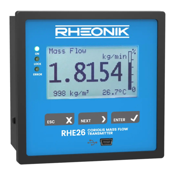
Summarization of Contents
General Information
Important Safety Instructions
Crucial safety guidelines for operating Coriolis flowmeters and handling potential hazards.
Manufacturer's Liability
Outlines Rheonik's liability regarding product use, consequential damages, and warranty terms.
Additional Resources
Points users to further documentation and resources for the RHE26/27, including the Desktop Reference.
Quick Start
System Components
Describes the typical components of a complete flowmeter system: sensor, transmitter, and cable.
Preparation Steps
Outlines the essential steps to prepare the flow meter for operation, including installation and calibration.
Installation
Mechanical Installation
Details panel mount dimensions and installation considerations for RHE26/27 housings compliant to IEC 61554.
Electrical Installation
Covers electrical connections for transmitters, including connector color coding and cable types.
Interconnecting RHE/RHM
Explains the use of Rheonik's specific cable for connecting RHE to RHM sensors and lists connection types.
Power Supply and Grounding
Covers power supply options (DC/AC) and essential grounding requirements for safe operation.
Digital Outputs
Explains the functionality, types, and configuration of digital outputs on RHE26/27 transmitters.
Analog Outputs
Details the configuration and types of analog outputs for RHE27 and RHE26 transmitters.
Digital Inputs
Describes the configuration and operation of digital inputs on RHE26/27 transmitters.
Analog Input
Explains the configuration of the 4-20mA analog input for external transmitters on RHE27.
Operation and Configuration
Function of the Pushbuttons
Details the function of the three front panel pushbuttons (ESC, NEXT, ENTER) in various contexts.
Passcodes and Menu Selection
Explains the use of passcodes for accessing USER and SERVICE levels and menu navigation.
Zero Offset Calibration
Guides users through the process of performing a zero offset calibration for the RHM sensor.
Change of Positive Flow Direction
Describes how to reverse the flow direction indication in the transmitter settings.
Temperature Measurement Configuration
Details how to configure the temperature measurement type for RHE/RHM systems.
Analog Output Configuration
Guides the configuration of analog output settings for RHE26/27, including ranges and fire states.
Digital Output Configuration
Explains how to configure digital and pulse outputs based on various parameters and alarm types.
Digital Input Configuration
Details how to configure the properties and functionality of digital inputs DI1 and DI2.
Remote Operation
USB Interface
Describes the USB interface for temporary PC connection, setup, configuration, and data logging.
RS485 Interface
Explains the RS485 interface for permanent connection, Modbus protocol, and termination resistors.
HART Interface
Covers the optional HART interface for analog output communication and its connection requirements.
Service and Maintenance
Maintenance and Calibration
Discusses maintenance requirements and field/lab calibration options for flow meters.
Troubleshooting
Guides users on identifying and resolving errors, warnings, and connection issues using status codes.
Service
States that the unit has no user-serviceable parts and advises contacting support for assistance.
WEEE and RoHS Compliance
Confirms the transmitters' compliance with WEEE and RoHS directives.
Ordering Code
RHE26 Ordering Options
Provides the ordering code structure and available options for the RHE26 model.
RHE27 Ordering Options
Details the ordering code structure and available options for the RHE27 model.
Appendix A Ex-Safety Instructions
Safety Instructions for Hazardous Areas
Lists critical safety instructions for installing equipment in hazardous areas, covering standards and cable length.
System Description
Describes the components of a hazardous area mass flow meter system, including intrinsically safe sensors.
Electrical Safety Limits
Specifies voltage and current limits for various signals and power supply connections for safe operation.
Thermal Safety Limits
States that no specific temperature class is assigned for safe operation of RHE26/27.
Grounding and Shielding
Details grounding requirements and shielding recommendations for RHM and RHE connections.
Installation in Safe Area
Specifies that RHE26/27 transmitters must be installed in ordinary (non-hazardous) locations.
Electrical Connection of Power Supply and I/O
Covers connection details for power supply and I/O terminals, including terminal types and cross-sections.
Electrical Connection to RHM
Shows the electrical connections between RHM sensors and RHE transmitters, including hazardous area certifications.
Ordering Code for Hazardous Areas
Explains the structure of the ordering code relevant for hazardous area certifications and options.
Technical Data
Lists operational limits like electrical data, operating temperatures, humidity, and altitude.
Compliance Standards
Details the ATEX, IECEx, and CSA standards and directives RHE26/27 complies with for hazardous areas.
Service and Repair
States that the unit has no user-serviceable parts and advises contacting support for repairs.
Contact Address
Provides Rheonik Messtechnik GmbH's official contact information, website, and email.
Appendix B Technical Information
Technical Data Summary
Summarizes key technical specifications including housing, ratings, power supply, connections, and interfaces.
Mechanical Drawings
Displays mechanical dimensions and connection diagrams for RHE26 transmitter variants.
RHE26 Mechanical Drawings
Provides detailed mechanical dimensions for RHE26 transmitter models E1 and E2.
RHE27 Mechanical Drawings
Presents mechanical dimensions for RHE27 transmitter model E1.


Need help?
Do you have a question about the RHE27 and is the answer not in the manual?
Questions and answers