
Related Manuals for RHEONIK RHE21


Summary of Contents for RHEONIK RHE21
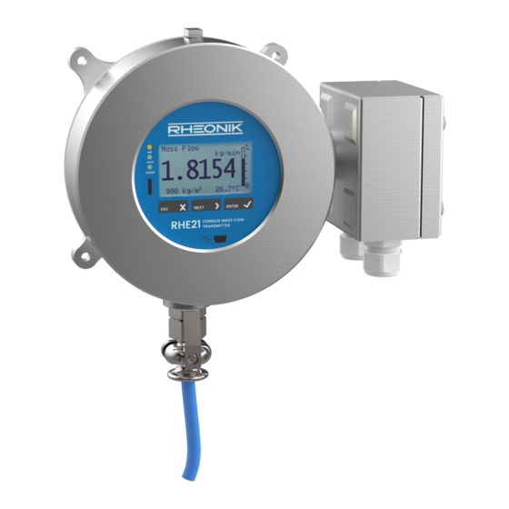
- Page 1 RHE21 Installation & Startup Guide RHE21 Installation & Startup Guide – Doc. No. 8.2.1.04 – Ver. 1.31 1 / 58 D o c u m e n t N o . : 8 . 2 . 1 . 0 4...
-
Page 2: Table Of Contents
Output Configuration ......................24 Analog Output Configuration ................... 24 Digital Output Configuration .................... 25 Digital Input Configuration ....................28 5 Remote Operation ......................29 RS485 ..........................29 RHE21 Installation & Startup Guide – Doc. No. 8.2.1.04 – Ver. 1.31 2 / 58... - Page 3 Contact address ........................ 42 Appendix B Technical Information .................. 43 Technical Data ........................43 Mechanical Drawings ....................... 45 Mounting Drawing ......................51 Appendix C CE Certificates ....................52 RHE21 Installation & Startup Guide – Doc. No. 8.2.1.04 – Ver. 1.31 3 / 58...
-
Page 4: General Information
General Information Important Safety Instructions for operating Coriolis Flowmeters For RHE21 units requiring 12 to 24V DC power, the use of a properly grounded (PELV) supply is highly recommended. The use of shielded cables for all I/O signals is recommended to prevent interference from high level EMI. -
Page 5: Quick Start
IP66 / type 4X. The RHE21-EP can also be installed behind a panel. The RHE21 should be mounted with 4 screws M6 or #12 (e.g. UNC12-24) on a metal mounting plate with minimum thickness of 6mm (1/4”). -
Page 6: Electrical Installation
RHM sensor. They can be directly connected to the RHM sensor according to Tables 2 to 5. The RHE21 construction types E5 and H3 have to be connected to an RHM sensor according to Tables 2 to 5 using the bottom RHE21 terminal box. Only interconnecting cable (ARHE-Cx cable) supplied by Rheonik should be used to connect an RHE to an RHM. -
Page 7: Rhm Electrical Connection Type Tm (Ptfe Cable)
Connection only necessary for RHE21 construction types E5 and H3 without integrated sensor cable. The RHM has 2 terminals for the connection of the cable shield. One is connected directly to PE, the other via a 1nF capacitor (PE C). -
Page 8: Rhm Electrical Connection Type Jo (12 Terminals)
PT2 Tor. Sense Connection only necessary for RHE21 construction types E5 and H3 without integrated sensor cable. The shield of the cable is connected through terminal 10 to the housing of the RHM. If there is a risk of a significant potential difference between the housing of the RHM and the PE terminal of the RHE, the shield should be connected to the RHE PE connection via a 1nF capacitor. -
Page 9: Legacy Rhm Sensors (9 Terminals)
(yel/grn) Shield Connection only necessary for RHE21 construction types E5 and H3 without integrated sensor cable. The shield of the cable is connected to the housing of the RHM using a screw terminal in the junction box. If there is a risk of a significant potential difference between the housing of the RHM and the PE terminal of the RHE, the shield should be connected to the RHE PE connection via a 1nF capacitor. - Page 10 “ -.--°C/°F ” please check the temperature measurement configuration setting in the RHE (section 4.5). The correct temperature measurement configuration setting for an RHM legacy sensor is “1”. RHE21 Installation & Startup Guide – Doc. No. 8.2.1.04 – Ver. 1.31 10 / 58...
-
Page 11: Power Supply, Grounding And I/O Connections Overview
Figure 5. The available I/O connections depend on the I/O configuration option of the RHE21. Figure 5: RHE21 Types E* with Terminal Box for Power Supply, I/O Connection and optional Layout For RHE21 constructions types H* the power supply and I/O connections are located in the housing of the transmitter as shown in Figure 6. - Page 12 0.35mm² (AWG 22) for DC supply cables and 0.5mm² (AWG 20) for mains supply cables. The RHE21 do not contain a mains switch. A switch or circuit breaker close to the RHE21 must be included in the supply line. The switch must be marked correspondingly.
-
Page 13: Grounding
3.2.2.1 Grounding RHE21 transmitters must be grounded. Ground the RHE by either connecting a ground to terminal 22 (PE) or to the M4 screw type terminal on the left lower mounting flange. The cross sectional area of the grounding wire must be equal to or larger than the conductors used for any supply or I/O connection. -
Page 14: Ac And Dc Supply
Outputs DO3 and DO4 are control/status outputs only. Digital outputs are push-pull outputs compliant to IEC 60946. They can drive loads connected to ground and loads connected to +24V. RHE21 Installation & Startup Guide – Doc. No. 8.2.1.04 – Ver. 1.31 14 / 58... - Page 15 NOTE: Intrinsically safe I/O circuits must only be operated with certified barriers or isolating amplifiers The RHE21 can be supplied with up to two intrinsically safe digital outputs. Outputs DO1 and DO2 are universal outputs and can be used as frequency, pulse or control/status outputs.
-
Page 16: Analog Outputs
Connect the output of the RHE to the isolating switching amplifier. If an open collector output of the RHE21 is connected to a NAMUR isolating switching amplifier, it might be recommended to disable the short / open supervision of the amplifier. - Page 17 24Vdc supply, the maximum total load resistance is 600 Ω. For analog outputs with HART communication, a load resistance of 250 Ω is recommended. RHE21 Installation & Startup Guide – Doc. No. 8.2.1.04 – Ver. 1.31 17 / 58...
-
Page 18: Digital Inputs
NOTE: Intrinsically safe I/O circuits must only be operated with certified barriers or isolating amplifiers An RHE21 transmitter can be supplied with up to two passive floating 4-20 mA analog outputs. Output 1 can optionally be equipped with a HART digital communications interface. -
Page 19: Analog Input
3.2.3.4 Analog Input The RHE21-E5 or RHE21-H3 can be equipped with a 4-20 mA analog input for connecting an external transmitter (such as a pressure sensor) with a passive 4-20 mA output. The RHE21 transmitter provides power to the connected devices’ output. -
Page 20: Operation And Configuration
This chapter gives a short introduction into operation of the RHE21 through the front panel user interface. For more detailed information, please refer to the RHE2X Desktop Reference Manual. -
Page 21: Passcodes And Menu Selection
Figure 18: Example - RHE21 Top Level Menu Selection Passcodes and Menu Selection To configure and carry out certain functions in an RHE21 transmitter, it is necessary to enter a predetermined passcode. Passcodes protect configuration setup and prevent inadvertent changes to the flow meter operating condition. There are two different access levels with separate passcodes: “USER”... -
Page 22: Zero Offset Calibration
EXIT pushbutton twice. Change of Positive Flow Direction Rheonik mass flow meters are bi-directional and can operate with flow passing through them in any direction. In some cases after installation, the transmitter may read negatively because of orientation. -
Page 23: Temperature Measurement Configuration
RHM flow meter body requires accessing the temperature measurement configuration menu item as shown in Figure 21. Main Screen Figure 21: RHE21 Menu - Temperature Measurement Configuration RHE21 Installation & Startup Guide – Doc. No. 8.2.1.04 – Ver. 1.31 23 / 58... -
Page 24: Output Configuration
6. If necessary set a damping factor [C/B17] and damping band range [C/B18] If the RHE21 is equipped with only one analog output use “Analog Output 2 [B]” for configuration. -
Page 25: Digital Output Configuration
2. Select a configuration for the pulse output according to the options stated in Table 10 under ID [R/S01] or for the status output under ID [I-L01] RHE21 Installation & Startup Guide – Doc. No. 8.2.1.04 – Ver. 1.31 25 / 58... - Page 26 13: Mass Flow Rate RHE Compatibility Mode Frequency Output. → set [R/S04 & 07] Freq. mode of 14: Volume Flow Rate RHE Compatibility Mode Frequency Output. previous RHE → set [R/S05 & 07] RHE21 Installation & Startup Guide – Doc. No. 8.2.1.04 – Ver. 1.31 26 / 58...
- Page 27 Digital Output Channel 0 Alarm High: [I-L04] DigOutCh0/1/A/BAlmHigh Alarm high value, see DigOutCh0/1/A/BAlmType. Must be a floating point value of 0.0 or higher. See DigOutCh0/1/A/BAlmLow for the unit specification. RHE21 Installation & Startup Guide – Doc. No. 8.2.1.04 – Ver. 1.31 27 / 58...
-
Page 28: Digital Input Configuration
A transition from high to low at DI1/2 stops the totalizers when they are in the running state. A transition from low to high at DI1/2 restarts the totalizers when they are in the stopped state. RHE21 Installation & Startup Guide – Doc. No. 8.2.1.04 – Ver. 1.31 28 / 58... -
Page 29: Remote Operation
Manual for a detailed description of the interface and register set. The RHE21 transmitter features an internal 120 Ω termination resistor with a switch at the back side of the transmitter. Normally, the termination switch (and the factory default position) should be set to ON. -
Page 30: Hart
Connect the analog output 1 as described in chapter 3.2.3.1.2 to a HART host input. A 250 Ω load resistor is recommended when connecting a HART modem. For a full description of the available HART register set, refer to the RHE2X HART manual. RHE21 Installation & Startup Guide – Doc. No. 8.2.1.04 – Ver. 1.31 30 / 58... -
Page 31: Service And Maintenance
The RHECom software can also be used to read out error codes, please refer to the RHECom quick guide. RHE21 Installation & Startup Guide – Doc. No. 8.2.1.04 – Ver. 1.31 31 / 58... -
Page 32: Service
RHE2X transmitters do not contain any user serviceable parts. Please contact your local sales/support agent or Rheonik Support for assistance. WEEE and RoHS RHE21 transmitters are not subject to the WEEE directive and are fully compliant to the RoHS directive. Ordering Code RHE21 Installation &... -
Page 33: Appendix A Ex-Safety Instructions
The sensor cable connection between sensor RHM and the transmitter RHE or the barrier EZB is intrinsically safe. Only the cable delivered by Rheonik may be used. The use of any other cable shall be clarified with Rheonik beforehand. -
Page 34: System Description
– be mounted in zone 0, zone 1 or zone 2. For the American market versions for div. 1 and for div 2 are available. The RHE21 is an associated equipment and contains the barriers for the RHM to be connected. Depending on the certification the transmitter RHE21 may be mounted in the following areas:... - Page 35 Power supply and RS485 (Only RHE21-E*D1-**I*-A***-***): Signal Terminals Type Nominal Voltage DC supply 20,21 Supply 10 – 28V RS485 70, 71 Interface 70 to 71: ±5V; 70 or 71 to PE: 30V**) (Connector) Interface **) The nominal signal Voltage between 70 and 71 is 3.3V. The interface is floating but clamped to PE with a clamping voltage of 30V.
-
Page 36: Thermal Safety Limits
RHE21-E* (ATEX/IECEx only): The RHE21-E* have 2 cable glands M16x1.5 with a clamping range 4 – 11mm for I/O and power supply. Options with 2 threads M25 or ½” NPT or 3/4” NPT are available upon request. In that case the user is responsible for using correspondingly certified cable glands. - Page 37 Special conditions for CSA certified units RHE21 marked Class I, Div. 1, Group A, B, C, D and/or Class I, Zone 1, A/Ex db [ia Ga] IIC T4 Gb 1. Shall be installed in class I, Division 1 / Zone 1 location.
-
Page 38: Electrical Connection Of Power Supply And I/O
Electrical connection of power supply and I/O As all I/O and supply terminals of the RHE21 are rated for Um = 250V, there are no special rules for installation. National and local standards regarding electrical installations must be observed. For information regarding function and usage of the different I/O and supply circuits refer to the corresponding chapters of the main manual. - Page 39 RHM with fixed cable, please refer to chapter 4 “Electrical Installation” and to appendix A “Ex-safety instructions” of the RHM manual. The RHE21-E5 and -H3 have cage clamp terminals for RHM and pressure sensor. Conductor cross-section: 0.2 – 2.5mm²...
-
Page 40: Ordering Code
CSA (USA and Canada) C1 = class I, Div. 1 / Ex db [ia Ga] IIC T4 Gb RHE21 in zone 1 or 2, Div. 1 or 2 C2 = class I, Div. 2 / Ex nA [ia Ga] IIC T4 Gc RHE21 in zone 2, Div. -
Page 41: Technical Data
3000m, higher maximum altitude upon request For the complete technical data refer to appendix B “Technical Data”. A.11 Compliance The RHE21 certified according to ATEX / IECEx comply with the following standards for hazardous areas: IEC 60079-0 IEC 60079-1... -
Page 42: Service And Repair
The unit does not contain any user serviceable parts and must not be opened by the user. If the unit gets modified in any way, the Ex-certification gets void. In case of malfunction connect your dealer or directly Rheonik Messtechnik GmbH A.13... -
Page 43: Appendix B Technical Information
Appendix B Technical Information Technical Data General Data Housing: Wall Mount for harsh environment Material: SS316, connection box SS316 or aluminum Enclosure Rating: IP66 / NEMA 7X; IP67 optionally Ambient Temperature: -20°C to +60°C (-4°F to +140°F); -40 to +60°C optionally Humidity: 10 to 90% relative humidity, non-condensing Altitude:... - Page 44 Digital Universal Outputs Output signal: Pulse, Frequency, Status Type: 24V push-pull, according to IEC60946 Maximum current: 20mA (high state), 100mA (low state) Frequency range: 0 ... 10 kHz Quantity: Up to 2, depending on I/O configuration Output value: programmable Digital Status Outputs Output signal: Status Type:...
-
Page 45: Mechanical Drawings
Mechanical Drawings Type E1, E2 Figure 15: RHE27 Transmitter Dimensions and Rear View RHE21-E1,E2 Transmitter Dimensions (all dimensions in mm) Appendix B: Technical Information – Ver. 1.00 45 / 58... - Page 46 Type E3, E4 RHE21-E3,E4 Transmitter Dimensions (all dimensions in mm) Appendix B: Technical Information – Ver. 1.00 46 / 58...
- Page 47 Type E5 RHE21-E5 Transmitter Dimensions (all dimensions in mm) Appendix B: Technical Information – Ver. 1.00 47 / 58...
- Page 48 Type EP RHE21-EP Transmitter Dimensions (all dimensions in mm), type EP for panel mount: 8 mm recessed I/O terminal box to fit RHE21 display front into panel window Appendix B: Technical Information – Ver. 1.00 48 / 58...
- Page 49 Type H1, H2 RHE21-H1,H2 Transmitter Dimensions (all dimensions in mm), figure shows CSA version ATEX/IECEx version has the same sensor connection part as type E1, E2, E3, E4 Appendix B: Technical Information – Ver. 1.00 49 / 58...
- Page 50 Type H3 RHE21-H3 Transmitter Dimensions (all dimensions in mm), bottom sensor connection box with 1 x M16 gland standard, 2 x M16 glands only with analog input option Appendix B: Technical Information – Ver. 1.00 50 / 58...
-
Page 51: Mounting Drawing
Mounting Drawing RHE21 pipe bracket mounting with accessory ARHE21-H (all dimensions in mm [inches]) The mounting brackets are designed for a 2” pipe (60.3mm / 2.4” outer diameter). The screws must be tightened with a torque of 5 ± 1 Nm. -
Page 52: Appendix Cce Certificates
Appendix C CE Certificates Appendix C: CE Certificates 52 / 58... - Page 53 Appendix C: CE Certificates 53 / 58...
- Page 54 Appendix C: CE Certificates 54 / 58...
- Page 55 Appendix C: CE Certificates 55 / 58...
- Page 56 Appendix C: CE Certificates 56 / 58...
- Page 57 Appendix C: CE Certificates 57 / 58...
- Page 58 D o c u m e n t N o . : 8 . 2 . 1 . 0 4 V e r s i o n 1 . 3 1 A P R - 2 0 2 1...
Need help?
Do you have a question about the RHE21 and is the answer not in the manual?
Questions and answers